
Recomendados
Más contenido relacionado
La actualidad más candente
La actualidad más candente (20)
Similar a Kubota b6100 d tractor service repair manual
Similar a Kubota b6100 d tractor service repair manual (14)
Más de fusjjfksekmme
Más de fusjjfksekmme (20)
Último
Último (20)
Kubota b6100 d tractor service repair manual
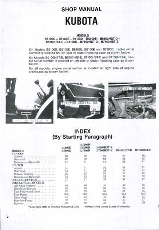
- 1. SHOP MANUAL KUBOTA MODELS B5100D-B5100E-B6100D-B6100E-B6100HST-D- B6100HST-E-B7100D-B7100HST.D-B7100HST E On Models B5100D, B5100E, B6100D, B6100E and B7100D, tractor serial number is located on left side of ciutch housing case as shown below. On Models B6100HST-D, B6100HST-E, B7100HST-D and B7100HST-E, trac- tor serial number is located on left side of clutch housing case as shown below. On all models, engine serial number is located on right side of engine crankcase as shown below. CTOR Si: RIAL NO. INDEX (By Starting Paragraph) B5100E MODELS B6100E BRAKES Adjust 80 Overhaul 82 Remove and Reinstall 81 CLUTCH Adjust 51 Overhaul 54 Release Bearing 55 Remove and Reinstall 53 COOLING SYSTEM 47 DIESEL FUEL SYSTEM Air Filter System 46 Bleed Fuel System 36 Fuel Filters and Lines 35 Fuel Pump 36A Glow Plugs 45 Injection Pump 37 Injector 39 ®Copyright 1986 by Intertec Publishing Corp. B5100D B6100D B7100D 80 82 81 51 54 55 53 47 46 36 35 36A 45 37 39 B6100HST-E B7100HST-E 80 82 81 51 54 ' 55 53 47 46 . , 36 35 36A 45 37 B6100HST-D 80 82 81 51 54 55 53 47 46 36 35 36A 45 37 39 B7100HST-D 80 82 81 51 54 55 53 47 46 36 35 36A 45 37 39 Printed in the United States of America.
- 2. MODELS INDEX (Cont.) B5100E B6100E B5100D B6100D B7100D B6100HST-E B7100HST-E B6iaOHST-D B7100HST-D DIFFERENTIAL Lock 77 Overhaul 76 Remove and Reinstall 75 ELECTRICAL SYSTEM Alternator 48 Starter 49 ENGINE Assembly, R&R 18 Camshaft 29 Compression Pressure 19 Compression Release 21 Connecting Rod and Bearings 28 Crankshaft and Bearings 30 Cylinder Head 22 Cylinder Liner 31 Flywheel 33 Governor 34 Oil Pump 32 Piston Pin 27 Piston and Rings 26 Piston and Rod Units, R&R 25 Timing Gears and Cover 24 Valve System 23 Valve Tappet Gap 20 FINAL DRIVE Overhaul 79 Remove and Reinstall 78 FRONT SYSTEM & STEERING Axle, R&R 2 Kingpins and Bushings Pivot Pin and Bushings 8 Steering Spindles 5 Steering Gear 9 Tie Rods and Toe-In 1 FRONT-WHEEL DRIVE SYSTEM Differential and Bevel Gear Assembly Outer Drive Assembly Outer Cover, Outer Drive Housing, Gear Case and Drive Components Outer Drive Housing, Axle Shafts and Axle Case GEAR TRANSMISSION Overhaul 74 Remove and Reinstall 73 HYDRAULIC SYSTEM Control Valve, Overhaul 98 Control Valve, R&R 97 Fluid and Filters 90 Lift Cover, Overhaul 100 Lift Cover, R&R 99 Lines 94 Pump, Overhaul 96 Pump, R&R 95 Tests and Adjustments 91 HYDROSTATIC TRANSMISSION Linkage, Adjust Linkage, Overhaul 77 76 75 48 49 18 29 19 21 28 30 22 31 33 34 32 27 26 25 24 23 20 79 78 3 6 12 10 11 74 73 98 97 90 100 99 94 96 95 91 77 76 75 48 49 18 29 19 21 28 30 22 31 33 34 32 27 26 25 24 23 20 79 78 5 9 1 70 69 98 97 90 100 99 94 96 95 91 63 64 77 76 75 48 49 18 29 19 21 28 30 22 31 33 34 32 27 26 25 24 23 20 79 78 3 6 12 10 11 70 69 98 97 90 100 99 94 96 95 91 63 64 77 76 75 48 49 18 29 19 21 28 30 22 31 33 34 32 27 26 25 24 23 20 79 78 4 7 14 13 70 69 98 97 90 100 99 94 96 95 91 63 64
- 3. INDEX (Cont.) B5100E MODELS B6100E HYDROSTATIC TRANSMISSION CONT. Overhaul • • • • Pressure Test . • •. Remove and Reinstall POWER TAKE-OFF Gear Transmission Components 89 Mid-Pto Rear Pto 88 SEPARATION Engine/Clutch Housing 52 Clutch Housing/Trans- mission Case 72 B5100D B6100D B7100D 89 88* 52 72 B6100HST-E B7100HST-E 67 57 66 85 86 84 52 65 B6100HST-D 67 57 66 85 86 84 52 65 B7100HST-D 67 57 66 85 86 84 52 65 DUAL DIMENSIONS This service manual provides specifications in both the U.S. Customary and Metric (SI) systems of measurement. The first specification is given in the measuring system perceived by us to be the preferred system when ser- vicing a particular component, while the second specification (given in parenthesis) is the converted measurement. For instance, a specification of "0.28 mm (0.011 inch)" would indicate that we feel the preferred measure- ment, in this instance, is the metric system of measurement and the U.S. system equivalent of 0.28 mm is 0.011 inch. CONDENSED SERVICE DATA B5100D MODELS B5100E GENERAL Engine Make Own Engine Model Z500-1A Number of Cylinders 2 Bore (mm) 68 (Inches) 2-5/8 Stroke (mm) 70 (Inches) 2-3/4 Displacement (cc) 508 (Cubic Inches) 31 Compression Ratio 22:1 TUNE-UP Valve Tappet Gap (Cold) (mm) 0.15-0.20 (Inch) 0.006-0.008 Injection Timing (BTDC) 25° Timing Mark Location Flywheel Iniection Pressure (MPa) 13.7 (PSI) 1988 Battery- Volts 12 Capacity Amp/hr 35 Ground Polarity Negative Slow Idle Speed (RPM) 750-800 High Idle Speed (RPM) 3000 Rated Speed(RPM) 3000 Horsepower at Pto Shaft 9.5 B6100D B6100E Own D650-A 3 64 2-1/2 70 2-3/4 675 41.2 22:1 0.15-0.20 0.006-0.008 25° Flywheel 13.7 1988 12 45 Negative 750-800 2800 2800 11 B6100HST-D B6100HST-E Own D650-AH 3 64 2-1/2 70 2-3/4 675 41.2 22:1 0.15-0.20 0.006-0.008 25° Flywheel 13.7 1988 12 45 Negative 750-800 2800 2800 11 B7100D Own D750-A 3 68 2-5/8 70 2-3/4 762 46.5 22:1 0.15-0.20 0.006-0.008 25° Flywheel 13.7 1988 12 45 Negative 750-800 2800 2800 13 B7100HST-D B7100HST-E Own D750-AH 8 68 2-5/8 70 2-3/4 762 46.5 22:1 0.15-0.20 0.006-0.008 25° Flywheel 13.7 1988 12 45 Negative 750-800 2800 2800 13
- 4. INDEX (Cont.) B5100E MODELS B6100E HYDROSTATIC TRANSMISSION CONT. Overhaul • • • • Pressure Test . • •. Remove and Reinstall POWER TAKE-OFF Gear Transmission Components 89 Mid-Pto Rear Pto 88 SEPARATION Engine/Clutch Housing 52 Clutch Housing/Trans- mission Case 72 B5100D B6100D B7100D 89 88* 52 72 B6100HST-E B7100HST-E 67 57 66 85 86 84 52 65 B6100HST-D 67 57 66 85 86 84 52 65 B7100HST-D 67 57 66 85 86 84 52 65 DUAL DIMENSIONS This service manual provides specifications in both the U.S. Customary and Metric (SI) systems of measurement. The first specification is given in the measuring system perceived by us to be the preferred system when ser- vicing a particular component, while the second specification (given in parenthesis) is the converted measurement. For instance, a specification of "0.28 mm (0.011 inch)" would indicate that we feel the preferred measure- ment, in this instance, is the metric system of measurement and the U.S. system equivalent of 0.28 mm is 0.011 inch. CONDENSED SERVICE DATA B5100D MODELS B5100E GENERAL Engine Make Own Engine Model Z500-1A Number of Cylinders 2 Bore (mm) 68 (Inches) 2-5/8 Stroke (mm) 70 (Inches) 2-3/4 Displacement (cc) 508 (Cubic Inches) 31 Compression Ratio 22:1 TUNE-UP Valve Tappet Gap (Cold) (mm) 0.15-0.20 (Inch) 0.006-0.008 Injection Timing (BTDC) 25° Timing Mark Location Flywheel Iniection Pressure (MPa) 13.7 (PSI) 1988 Battery- Volts 12 Capacity Amp/hr 35 Ground Polarity Negative Slow Idle Speed (RPM) 750-800 High Idle Speed (RPM) 3000 Rated Speed(RPM) 3000 Horsepower at Pto Shaft 9.5 B6100D B6100E Own D650-A 3 64 2-1/2 70 2-3/4 675 41.2 22:1 0.15-0.20 0.006-0.008 25° Flywheel 13.7 1988 12 45 Negative 750-800 2800 2800 11 B6100HST-D B6100HST-E Own D650-AH 3 64 2-1/2 70 2-3/4 675 41.2 22:1 0.15-0.20 0.006-0.008 25° Flywheel 13.7 1988 12 45 Negative 750-800 2800 2800 11 B7100D Own D750-A 3 68 2-5/8 70 2-3/4 762 46.5 22:1 0.15-0.20 0.006-0.008 25° Flywheel 13.7 1988 12 45 Negative 750-800 2800 2800 13 B7100HST-D B7100HST-E Own D750-AH 8 68 2-5/8 70 2-3/4 762 46.5 22:1 0.15-0.20 0.006-0.008 25° Flywheel 13.7 1988 12 45 Negative 750-800 2800 2800 13
- 5. Paragraphs 1-3 KUBOTA FRONT AXLE AND STEERING SYSTEM Front axle is a fixed tread type. Camber angle, caster angle and king pin inclina- tion are non-adjustabie. Front axle assembly and support frame are hinged together by a singie pivot pin. Pivot pin removal can only be accomplish- ed after removing front axie assembly and support frame as a unit as outiined in paragraph 2. TIE RODS AND TOE-IN All Models 1. Tie rod and drag link ends are automotive type. Steering drag link is non-adjustable and must be renewed as an assembly. Tie rod assembly is renewable as separate components. Ad- just toe-in to 0-5 mm (0-0.2 inch) by shortening or lengthening tie rod. FRONT AXLE Two-Wheel Drive Models 2. REMOVE AND REINSTALL. Disconnect headlight wiring, then remove hood assembly. Open radiator drain cock and allow coolant to drain in- to a suitable container. Disconnect negative battery cable terminal from battery post. Remove air cleaner assembly, muffler and left and right side covers. Disconnect radiator hoses. Remove oil cooler lines at cooler as need- ed. Detach drag link (13-Fig. 1) from steering arm (17). Support tractor behind front axle, then support front ax- le level with floor to prevent tipping. Remove cap screws securing front axle support to engine block. Carefully move front axle assembly, support frame and radiator forward until clear of tractor. To complete disassembly, attach a suitable hoist or holding fixture to sup- port frame, then remove set spring (12), castle nut (11) and washer (10). Withdraw pivot pin (7), then separate front axle assembly from support frame. Installation is reverse of removal. Tighten castle nut (11) to 9.8 N-m (7 ft.-lbs.) torque. Tighten cap screws securing support frame to engine block to 48-56 N-m (35-41 ft.-lbs.) torque. Tighten drag link nut to 29-49 N-m (22-36 ft.-lbs.) torque. Replenish cooling system and transmission hydraulic fluids as needed. Models B51OOD - B61OOD - B6100HST-D-B7100D 3. REMOVE AND REINSTALL. Disconnect headlight wiring, then remove hood assembly. Open radiator drain cock and allow coolant to drain in- to a suitable container. Disconnect negative battery cable terminal from battery post. Remove air cleaner assembly, muffler and left and right side covers. Disconnect radiator hoses. Remove oil cooler lines at cooler as need- ed. Detach drag link from steering arm (26-Fig. 3). Support tractor behind front axle, then support front axle level with floor to prevent tipping. Loosen drive shaft protective cover band at joint case (89-Fig. 3 or 4) and remove drive p/g, 1~ Exploded view of front axie, spindie and hub assembly and steering linkage used on two-wheei drive modeis. 1. Front axle 2. Steering arm 3. Tie rod end 4. Grease fitting 5. Locknut 6. Tie rod 7. Pivot pin 8. "O"ring 9. Grease seal 10. Washer 11. Castle nut 12. Set spring 13. Drag link 14. Washer 15. Castle nut 16. Cotter key 17. Steering arm 18. Bolt 19. Lockwasher 20. Nut 21. Shim 22. Spacer 23. "0" ring 24. Bushings 25. Bearing 26. Collar 27. Grease seal 28. Key 29. Spindle 30. Grease seal 31. Bearing 32. Spacer 33. Hub Fig. 2-Exploded view of recircutating ball nut steer- ing gear used on all models. 1. Housing 2. Cap 3. Nut 4. Lockwasher 5. Flat washer 6. Steering wheel 7. Bushing 8. Column 9. Shim 10. Seal 11. Bearing 12. Worm gear & shaft 13. Bearing 14. Plug 15. Plug 16. Nut 17. Gasket 18. Cover 19. Shim 20. Adjusting screw 21. Sector shaft 22. Gasket 23. Seal 24. Pitman arm 25. Lockwasher 26. Nut 27. Drain plug shaft from joint case. Remove cap screws securing front axle support to engine block. Carefully move front axle assembly, support frame and radiator forward until clear of tractor unit. To complete disassembly, attach a suitable hoist or holding fixture to support frame, then remove set spring (9-Fig. 3), castle nut (8) and flat washer (7). Withdraw pivot pin (3), then separate front axle assembly from support frame. Installation is reverse of removal. 34. Bearing 35. Washer 36. Castle nut 37. Cotter key 38. Gasket 39. Cap
- 6. SHOP MANUAL Tighten castle nut (8) to 9.8 N-m (7 ft.-lbs.) torque. Tighten cap screws securing support frame to engine block to 48-56 N-m (35-41 ft.-lbs.) torque. Tighten drag link nut to 29-49 N-m (22-36 ft.-lbs.) torque. Replenish cooling system and transmission/hydraulic fluid as needed. Model B7100HST-D 4. REMOVE AND REINSTALL. Disconnect headlight wiring, then remove hood assembly. Open radiator drain cock and allow coolant to drain in- to a suitable container. Disconnect negative battery cable terminal from battery post. Remove air cleaner assembly, muffler and left and right side covers. Disconnect radiator hoses. Remove oil cooler lines at cooler. Detach drag link from steering arm (26 - Fig. 5). Support tractor behind front axle, then support front axle level with floor to pre- vent tipping. Loosen drive shaft protec- tive cover band at joint case (89) and remove drive shaft from joint case. Remove cap screws securing front axle support to engine block. Carefully move front axle assembly, support frame and radiator forward until clear of tractor. To complete disassembly, attach a suitable hoist or holding fixture to sup- port frame, then remove set spring (9), castle nut (8) and flat washer (7). With- draw pivot pin (3), then separate front axle assembly from support frame. Installation is reverse of removal. Tighten castle nut (8) to 9.8 N-m (7 ft.-lbs.) torque. Tighten cap screws securing support frame to engine block to 48-56 N-m (35-41 ft.-lbs.) torque. Tighten drag link nut to 29-49 N-m (22-36 ft.-lbs.) torque. Replenish cooling system and transmission/hydraulic fluid as needed. SPINDLES AND BUSHINGS Two-Wheel Drive Models 5. Spindle shaft (29-Fig. 1) outside diameter should be 19.948-19.980 mm (0.7854-0.7866 inch). Front axle spindle shaft bushings (24) should have an inside diameter of 20-20.051 mm (0.7874- 0.7894 inch). Clearance between spindle shaft (29) and front axle spindle shaft bushings (24) should be 0.020-0.103 mm (0.0008-0.0041 inch). Spindle, shaft should have no end play. Renew all parts as needed. If upper spindie shaft bushing (24) is renewed, press bushing below top sur- face of axle to provide sufficient room for "0" ring (23). Press seal (27) into position with lip of seal towards top. Tighten castle nut (36) to 82-86 N-m (61-64 ft.-lbs.) torque. KING PINS AND BUSHINGS Models B5100D - B6100D - B6100HST-D-B7100D 6. R&R AND OVERHAUL. Bend lock tab (54 - Fig. 3) away from screw head, then remove screw (53). Withdraw lower king pin (56). Unbolt and remove steering arm (26), then withdraw upper king pin (46). Separate outer drive assembly and axle shaft from front axle. Standard king pin bushing inner diameter is 20.020-20.053 mm (0.7882-0.7895 inch). Standard king pin outside diameter is 19.979-20.000 mm (0.7866-0.7874 inch). Recommended clearance between king pin and bushing is 0.020-0.074 mm (0.0008-0.0029 inch). Reassembly is reverse order of disas- sembly. Lubricate king pins with a good quality, multi-purpose, lithium base grease, then slide into position. NOTE: King pins should siide freely into bushing bores with just hand pressure, DO NOT drive king pins in with a hammer. Tighten steering arm retaining screws to 39-49 N-m (29-36 ft.-lbs.). Model B7100HST-D 7. R&R AND OVERHAUL. Upper support (king pin) and bushing are ac- cessible after removing steering arm (26-Fig. 5). Outside diameter of sup- port (44) end should be 25.000-25.033 mm (0.9843-0.9856 inch). Bushing (42) inside diameter should be 25.050-25.085 mm (0.9862-0.9876 inch). Clearance be- tween bushing (42) and king pin (44) should be 0.017-0.085 mm (0.0007- 0.0033 inch). The lower end of the outer drive hous- ing is supported by support cover (72) and rotates around bearing (69). Refer to outer drive housing service section in paragraph 13 if bearing must be renew- ed as gear backlash may be affected. PIVOT PIN AND BUSHINGS All Models 8. R&R AND OVERHAUL. Remove front axle as previously outlined and refer to Fig. 1, 3 or 5. Pivot pin (7-Fig. 1 or 3-Fig. 3 or 5) outside diameter should be 19.88-20.03 mm (0.7827-0.7886 inch). Front axle pivot pin bushings should have an inside diameter of 20.10-20.15 mm (0.7913- 0.7933 inch). Clearance between pivot pin and front axle pivot pin bushings should be 0.07-0.27 mm (0.0028-0.0106 inch). Front axle-to-frame end play should be 0.02 mm (0.0008 inch). Paragraphs 4-9 STEERING GEAR All Models 9. R&R AND OVERHAUL. Raise hood, then disconnect negative battery cable terminal from battery post. Disconnect electrical connector under instrument panel. On hydrostatic drive models so equipped, remove Speed Set knob, cc^ver retaining cap screws and cover. Remove steering wheel cap (2-Fig. 2), then remove nut (3), lock- washer (4) and flat washer (5). Using a suitable puller, withdraw steering wheel (6). Remove four cap screws securing in- strument panel, then lift panel clear from column. Remove pitman arm securing nut (26) and lockwasher (25). Place a suitable alignment mark on sec- tor shaft end (21) and pitman arm (24) to ensure correct repositioning during reassembly. Using a suitable puller, withdraw pitman arm (24) from sector shaft end (21). On hydrostatic drive models so equipped, remove upper rod from Speed Set cam. Remove four bolts and nuts securing steering gear assembly to tractor unit, then lift clear. To disassemble, first remove drain plug (27) and allow oil to drain into a suitable container. Piemove any existing paint, rust or burrs from pitman arm end of sector shaft. Disassemble steer- ing gear assembly with reference to Fig. 2. Inspect and renew any components that are excessively worn or damaged. Worm gear and shaft (12-Fig. 2) are available only as an assembled unit and disassembly is not recomniended. End clearance of adjusting screw (20) in slot of sector shaft (21) is controlled by shim (19) which is available in five thicknesses. Install thickest possible shim when unit is assembled. Reassembly is reverse order of disassembly. Make sure center tooth on sector shaft (21) enters center tooth space on worm gear (12). After reassembly, fill ste(?ring gear through plug hole (14) with 0.2 liter (0.2 quart) of SAE 80 gear lube, then install and tighten plug (14). Installation of steering gear is reverse of removal. Install pitman arm (24) on sector shaft (21) while aligning marked splines. Install lockv/asher (25) and nut (26); tighten nut (26) to 118-157 N-m (87-116 ft.-lbs.) torque. Reinstall instru- ment panel. Install steering wheel (6), flat washer (5), lockwasher (4) and nut (3). Tighten nut (3) to 29-49 N-m (22-36 ft.-lbs.) torque. With worm gear and sec- tor shaft gear at center position, remove plug (15), loosen locknut (16) and turn adjusting screw (20) until steering wheel free movement is 10-30 mm (25/64 - 1-3/16 inches). Complete reassembly by reversing disassembly procedure.
- 7. Paragraphs 10-11 KUBOTA FRONT-WHEEL DRIVE SYSTEM (Models B5100D-B6100D-B6100HST-D-B7100D) Front-wheel drive assembly includes drive shaft, housing, differential, axie shafts and axie hub assembiies. Front- wheel drive power is supplied through transmission assembly and controlled by manualiy engaging or disengaging FWD select lever. Camber angle, caster angle and king pin inciination are non-adjustabie. Roiiing angle adjuster screw (1 - Fig. 3) should be adjusted to a height of 25 mm (0.9843 inch) measured from axle case (34) to top of screw head. Front wheel steering angle adjuster screw (47) (front and rear) should Fig. 3-Exploded view of front-wheel drive axle used on Model B5100D. Front-wheel drive axle used on Models B6100D, B$100H$T-D and B7100D is similar except for pinion gear assembiy and location of differentiai drain piug (see Fig. 4). 1. Adjuster screw 2. Locknut 3. Pivot pin 4. "0" ring 5. Bushing 6. "0" ring 7. Flat washer 8. Castle nut 9. Set spring 10. Gasket 11. Fill plug 12. Center case 13. Drain plug 14. Shim 15. Bearing 16. Cross-shaft 17. Differential case 18. Pin 19. Pin 20. Thrust washer 21. Side gear 22. Thrust washer 23. Spider gear 24. Bevel ring gear 25. Lock plate 26. Steering arm 27. Cotter key 28. Castle nut 29. Washer 30. Tie rod 31. Locknut 32. Tie rod end 33. Gasket 34. Axle case 35. Bushing 36. Bearing 37. Oil seal 38. Axle shaft 39. Pin 40. Yoke 41. Universal joint 42. Clip 43. Yoke shaft 44. Grease fitting 45. "0" ring 46. King pin 47. Adjuster screw 48. Locknut 49. Outer drive housing 50. Fill plug 51. Drain plug 52. Gasket 53. Retainer screw 54. Lock tab 55. Gasket 56. King pin 57. "0" ring 58. Oil seal 59. Bearing 60. Gear 61. Bearing 62. Snap ring 63. Bearing 64. Gear 65. Snap ring 66. Bearing 67. Gasket 68. Outer cover 69. Oil seal 70. Wheel axle 71. Dust cover 72. Felt seal 73. Dust seal 74. Dust seal holder 75. Gasket 76. Bevel pinion 77. Bearings 78. Spacer 79. Snap ring 80. Collar 81. Bushing 82. Snap ring 83. Oil seal 84. Yoke 85. Pin 86. Universal joint 87. Yoke 88. Gasket 89. Joint case be adjusted to a length of 22 mm (0.8661 inch) measured from outer drive housing (49) to top of screw head. OUTER DRIVE ASSEMBLY Models B5100D - B6100D - B6100HST-D-B7100D 10. R&R AND OVERHAUL. To dis- assemble outer drive assembly, first remove wheel from side to be serviced. Remove drain plug (51-Fig, 3) and allow lubricant to drain into a suitable container. Remove cap screws securing outer cover (68) to outer drive housing (49), then withdraw cover with com- ponents (63, 64, 65, 66, 69 and 70). NOTE: During removai, if gear (64) cat- ches on bearing (61), use suitabie tools and carefuliy drive against gear (64) forc- ing bearing (63) inward untii approximate- ly halfway off wheei axie (70). Remove bearing (63), gear (64) and snap ring (65) from wheel axle (70), then separate remaining components. Examine components for damage and excessive wear. Reassembly is reverse order of disassembly. NOTE: To ease instaliation of outer cover assembly, press bearing (63) onto wheei axie (70) oniy haifway. After in- stallation, lightiy tap wheei axie (70) to force bearing against shouider. Tighten cap screws securing outer drive cover (68) to outer drive housing (49) to 18-21 N-m (6-7 ft.-lbs.) torque. Remove plug (50) and fill axle gearcase with 0.15 liter (0.15 U.S. quart) of SAE 80 gear lube. Install and tighten plug (50). Reinstall wheel and tighten lug nuts to 63-73 N - m (46-54 ft.-lbs.) tor- que. OUTER DRIVE HOUSING, AXLE SHAFTS AND AXLE CASE Models B5100D - B6100D - B6100HST-D-B7100D 11. R&R AND OVERHAUL. Remove outer drive assembly as outlin- ed in paragraph 10. Remove drain plug (13-Fig. 3) on Model B5100D and plug (95-Fig. 4) on all other models and allow lubricant to drain into a suitable container. Detach tie rod end (32-Fig. 3) from steering arm (26). Remove cap screws securing dust cover (71), felt seal (72), dust seal (73), dust seal holder (74)
- 8. SHOP MANUAL and gasket (75), then slide components toward center. Remove snap ring (62), then slide bearing (61) and gear (60) from yoke shaft (43). Bend lock tab (54) away from head of retainer screw (53) and remove screw (53) with lock tab (54) and gasket (55). Withdraw king pin (56). Unbolt and remove steering arm (26), then withdraw king pin (46). Lift outer drive housing (49) from axle case (34). Slide components (71 through 75) off ax- le case. Withdraw axle shaft assembly (38 through 43). Remove cap screws securing axle case (34) to center case (12) and separate components. Use care not to allow differential assembly to fall free from center case. Inspect all components for damage and excessive wear. Inspect universal joint (41) for binding, roughness, ex- cessive wear or any other damage. Renew all parts as needed. Reassembly is reverse of disassembly. Tighten cap screws securing right side axle case to center case to 48-56 N-m (35-41 ft.-lbs.) torque. Tighten cap screws securing left side axle case to center case to 24-27 N-m (17-20 ft.-lbs.) torque. Tighten cap screws retaining steering arnn (26) to 39-49 N-m (29-86 ft.-lbs.) torque. Tighten tie rod end nut to 29.5-49.2 N-m (22-36 ft.-lbs.) torque. Complete reassembly as outlined in paragraph 10. Remove plug (11) and refill differential case with 0.5 liter (0.53 U.S. quart) of SAE 80 gear lube on Models B5100D, B6100D and B6100HST-D and 0.7 liter (0.74 U.S. quart) of SAE 80 gear lube on Model B7100D. Install and tighten plug (11). DIFFERENTIAL AND BEVEL GEAR ASSEMBLY Models B5100D - B6100D - B6100HSTD-B7100D 12. R&R AND OVERHAUL. Remove outer drive housing, king pins, axle shafts and left axle case as outlined in paragraph 11. Lift differential and bevel ring gear assembly (14 through 25-Fig. 3) from center case (12). Loosen drive shaft protective cover band at joint case (89-Fig. 8 or 4) and remove drive shaft from joint case. Use a suitable punch and hammer to drive pin (85) from yoke (84). Withdraw yokes (84 and 87) with universal joint (86) as a unit. On Model B5100D, remove joint case (89-Fig. 3), gasket (88), seal (83) and snap ring (79), then withdraw bevel pinion assembly. On Models B6100D, B6100HST-D and B7100D, remove cap screws securing joint case (89-P^ig. 4) and retaining plate (91), then withdraw bevel pinion assembly. To disassemble bevel pinion assembly on Model B5100D, remove snap ring (82-Fig. 8), then complete disassembly with reference to Fig. 3. To disassemble bevel pinion assembly on Models B6100D, B6100HST-D and B7100D, place bevel pinion (76-Fig. 4) in a suitable holding fixture, then remove nut (94) from pinion shaft. Complete disassembly with reference to Fig. 4. Inspect components for damage and excessive wear. Renew all parts as need- ed. Bevel pinion (76-Fig. 3 and 4) and bevel ring gear (24-Fig. 3) must be renewed as a matche'd set. Reassembly is reverse order of disassembly. On Models B6100D, B6100HST-D and B7100D, tighten nut (94-Fig. 4) to 98-147 N-m (72-108 ft.-lbs.) torque. To separate differential and bevel ring gear assembly, first bend tabs of lock plate (25-Fig. 8) away from screw heads, then remove cap screws securing bevel ring gear (24) to differential case (17). Use a suitalDle mallet and tap bevel ring gear (24) from differential case (17). Withdraw keys (18 and 19) and cross- shaft (16) from differential case (17), then separate components (20 through 28) from case (17). Use a suitable puller and associated tools to withdraw bear- ings (15) from differential case (17). Inspect components for damage and excessive wear. Renew all components as needed. Bevel ring gear (24) and bevel pinion (76 - Fig. 8 and 4) must be renew- ed as a matched set. Reassembly is reverse order of disassembly. Lubricate components with a light film of SAE 80 gear lube prior to installation. Tighten cap screws securing bevel ring (24) to differential case (17) to 29-84 N-m (22-25 ft.-lbs.), then bend tabs of lock plate (25) over to secure screws. Shims (14-Fig. 8) are used to adjust backlash between bevel ring gear and bevel pinion gear. Recommended backlash is 0.1-0.2 mm (0.004-0.008 Paragraphs 12-13 inch). Shims (14) are available in thicknesses of 0.2, 0.8 and 0.5 mm (0.008, 0.012 and 0.020 inch). Recom- mended pinion shaft end play is zero. Shims are available for Models B6100D, B6100HST-D and B7100D to adjust mesh position. After adjustment, add shims behind retainer plate (91-Fig. 4) until zero end play is attained. Reassemble outer drive housing, king pins, axle shafts and left axle case as outlined in paragraph 11. FRONT-WHEEL DRIVE SYSTEM (Model B7100HST-D) Front-wheel drive assembiy includes drive shaft, housing, differentiai, axle shafts and axle hub assembly. Front- wheel drive power is supplied through transmission assembly and controlled by manually engaging or disengaging FWD select lever. Camber angle, caster angle and king pin inclination are non- adjustable. Rolling angle adjuster screw (1 - Fig. 5) should be adjusted to a height of 25 mm (0.98 inch) measured from axle case (35) to top ol screw head. Front wheel steering angle adjuster screw (56) (front and rear) should be adjusted to a length of 22 mm (0.86 inch) measured from outer drive housing (58) to top of screw head. OUTER COVER, OUTER DRIVE HOUSING, GEARCASE AND DRIVE COMPONENTS 18. R&R AND OVERHAUL. Re- move wheel from side to be serviced. Remove drain plug (62-Fig. 6) and 11 12 Fig. 4 —Exploded view of bevei pinion gear assembly and differential case of the type used on Models B6100D, B6100HSTD and B7100D. Refer to Fig. 3 for identification of parts ex- cept for the foiiowing. 90. Gasket 91. Retainin>< plate 92. Bushin^^ 93. Seal 94. Nut 95. Drain plujr 96. Gasket 89
- 9. Thank you very much for your reading. Please Click Here. Then Get COMPLETE MANUAL. NO WAITING NOTE: If there is no response to click on the link above, please download the PDF document first and then click on it.
- 10. SHOP MANUAL and gasket (75), then slide components toward center. Remove snap ring (62), then slide bearing (61) and gear (60) from yoke shaft (43). Bend lock tab (54) away from head of retainer screw (53) and remove screw (53) with lock tab (54) and gasket (55). Withdraw king pin (56). Unbolt and remove steering arm (26), then withdraw king pin (46). Lift outer drive housing (49) from axle case (34). Slide components (71 through 75) off ax- le case. Withdraw axle shaft assembly (38 through 43). Remove cap screws securing axle case (34) to center case (12) and separate components. Use care not to allow differential assembly to fall free from center case. Inspect all components for damage and excessive wear. Inspect universal joint (41) for binding, roughness, ex- cessive wear or any other damage. Renew all parts as needed. Reassembly is reverse of disassembly. Tighten cap screws securing right side axle case to center case to 48-56 N-m (35-41 ft.-lbs.) torque. Tighten cap screws securing left side axle case to center case to 24-27 N-m (17-20 ft.-lbs.) torque. Tighten cap screws retaining steering arnn (26) to 39-49 N-m (29-86 ft.-lbs.) torque. Tighten tie rod end nut to 29.5-49.2 N-m (22-36 ft.-lbs.) torque. Complete reassembly as outlined in paragraph 10. Remove plug (11) and refill differential case with 0.5 liter (0.53 U.S. quart) of SAE 80 gear lube on Models B5100D, B6100D and B6100HST-D and 0.7 liter (0.74 U.S. quart) of SAE 80 gear lube on Model B7100D. Install and tighten plug (11). DIFFERENTIAL AND BEVEL GEAR ASSEMBLY Models B5100D - B6100D - B6100HSTD-B7100D 12. R&R AND OVERHAUL. Remove outer drive housing, king pins, axle shafts and left axle case as outlined in paragraph 11. Lift differential and bevel ring gear assembly (14 through 25-Fig. 3) from center case (12). Loosen drive shaft protective cover band at joint case (89-Fig. 8 or 4) and remove drive shaft from joint case. Use a suitable punch and hammer to drive pin (85) from yoke (84). Withdraw yokes (84 and 87) with universal joint (86) as a unit. On Model B5100D, remove joint case (89-Fig. 3), gasket (88), seal (83) and snap ring (79), then withdraw bevel pinion assembly. On Models B6100D, B6100HST-D and B7100D, remove cap screws securing joint case (89-P^ig. 4) and retaining plate (91), then withdraw bevel pinion assembly. To disassemble bevel pinion assembly on Model B5100D, remove snap ring (82-Fig. 8), then complete disassembly with reference to Fig. 3. To disassemble bevel pinion assembly on Models B6100D, B6100HST-D and B7100D, place bevel pinion (76-Fig. 4) in a suitable holding fixture, then remove nut (94) from pinion shaft. Complete disassembly with reference to Fig. 4. Inspect components for damage and excessive wear. Renew all parts as need- ed. Bevel pinion (76-Fig. 3 and 4) and bevel ring gear (24-Fig. 3) must be renewed as a matche'd set. Reassembly is reverse order of disassembly. On Models B6100D, B6100HST-D and B7100D, tighten nut (94-Fig. 4) to 98-147 N-m (72-108 ft.-lbs.) torque. To separate differential and bevel ring gear assembly, first bend tabs of lock plate (25-Fig. 8) away from screw heads, then remove cap screws securing bevel ring gear (24) to differential case (17). Use a suitalDle mallet and tap bevel ring gear (24) from differential case (17). Withdraw keys (18 and 19) and cross- shaft (16) from differential case (17), then separate components (20 through 28) from case (17). Use a suitable puller and associated tools to withdraw bear- ings (15) from differential case (17). Inspect components for damage and excessive wear. Renew all components as needed. Bevel ring gear (24) and bevel pinion (76 - Fig. 8 and 4) must be renew- ed as a matched set. Reassembly is reverse order of disassembly. Lubricate components with a light film of SAE 80 gear lube prior to installation. Tighten cap screws securing bevel ring (24) to differential case (17) to 29-84 N-m (22-25 ft.-lbs.), then bend tabs of lock plate (25) over to secure screws. Shims (14-Fig. 8) are used to adjust backlash between bevel ring gear and bevel pinion gear. Recommended backlash is 0.1-0.2 mm (0.004-0.008 Paragraphs 12-13 inch). Shims (14) are available in thicknesses of 0.2, 0.8 and 0.5 mm (0.008, 0.012 and 0.020 inch). Recom- mended pinion shaft end play is zero. Shims are available for Models B6100D, B6100HST-D and B7100D to adjust mesh position. After adjustment, add shims behind retainer plate (91-Fig. 4) until zero end play is attained. Reassemble outer drive housing, king pins, axle shafts and left axle case as outlined in paragraph 11. FRONT-WHEEL DRIVE SYSTEM (Model B7100HST-D) Front-wheel drive assembiy includes drive shaft, housing, differentiai, axle shafts and axle hub assembly. Front- wheel drive power is supplied through transmission assembly and controlled by manually engaging or disengaging FWD select lever. Camber angle, caster angle and king pin inclination are non- adjustable. Rolling angle adjuster screw (1 - Fig. 5) should be adjusted to a height of 25 mm (0.98 inch) measured from axle case (35) to top ol screw head. Front wheel steering angle adjuster screw (56) (front and rear) should be adjusted to a length of 22 mm (0.86 inch) measured from outer drive housing (58) to top of screw head. OUTER COVER, OUTER DRIVE HOUSING, GEARCASE AND DRIVE COMPONENTS 18. R&R AND OVERHAUL. Re- move wheel from side to be serviced. Remove drain plug (62-Fig. 6) and 11 12 Fig. 4 —Exploded view of bevei pinion gear assembly and differential case of the type used on Models B6100D, B6100HSTD and B7100D. Refer to Fig. 3 for identification of parts ex- cept for the foiiowing. 90. Gasket 91. Retainin>< plate 92. Bushin^^ 93. Seal 94. Nut 95. Drain plujr 96. Gasket 89
- 11. Paragraph 13 Cont. allow lubricant to drain into a suitable container. Detach tie rod end (32-Fig. 5) from steering arm (26). Remove cap screws securing gearcase (48) to axle case (34 or 35). Place a suitable drain pan under end of axle case, then lift complete outer drive assembly from axle case and place on a suitable work bench to complete disassembly. Note shims (47) located between axle case and gear- case. Extract axle shaft (96) with com- ponents (38, 39 and 40). Remove cap screws retaining steering arm (26) to outer drive housing (58), then separate arm from support end (44). Remove cap screws securing sup- port (44) to gearcase (48) and separate. Remove cap screws securing lower sup- port cover (72) to outer drive housing (58), then withdraw cover along with Fig. 5 1. Adjuster screw 2. Locknut 3. Pivot pin 4. "0" ring 5. Bushing 6. "Cring 7. Flat washer 8. Castle nut 9. Set spring 10. "0" ring 11. Fill plug 12. Gasket 13. Lockwasher 14. Shim 15. Bearing 16. Cross-shaft 17. Differential case 18. Pin 19. Pin 20. Shim 21. Side gear 22. Thrust washer 23. Spider gear 24. Bevel ring gear - Exploded view of front-wheei drive 25. Lockplate 26. Steering arm 27. Cotter key 28. Castle nut 29. Washer 30. Tie rod 31. Locknut 32. Tie rod end 33. Gasket 34. Left axle case 35. Right axle case 36. Drain plug 37. Gasket 38. Snap ring 39. Bearing 40. Gear 41. Shim 42. Bushing 43. "O" ring 44. Support 45. Gasket 46. Bearing 47. Shim 48. Gearcase axie used on Model 49. Dust seal 50. Snap ring 51. Gear 52. Bearing 53. Snap ring 54. Seal 55. Shaft 56. Adjuster screw 57. Locknut 58. Outer drive housing 59. Gasket 60. Fill plug 61. Gasket 62. Drain plug 63. "O" ring 64. Sleeve 65. Seal 66. Snap ring 67. Bearing 68. Gear 69. Bearing 70. Shim 71. "0" ring 72. Support cover KUBOTA gear (68) and bearing (69). Note shims (70). Using a suitable mallet, tap shaft (55) from bottom side to separate outer drive housing (58) from gearcase (48). Remove cap screws securing outer cover (82) to outer drive housing (58), then withdraw outer cover (82) assembly. Complete disassembly of components with reference to Fig. 5. Reassembly is reverse order of disassembly. Install new "0" rings and gasket (81). Be sure to install seal (54-Fig. 7) with lip facing towards top and seal (65) with lip facing towards bot- tom. Tighten cap screws securing outer cover (82-Fig. 5) to outer drive housing (58) to 48-56 N-m (35-41 ft.-lbs.) torque. Tighten cap screws securing support cover (72) to outer drive housing (58) to 24-27 N-m (17-20 ft.-lbs.) torque. Tighten cap screws securing support (44) to gearcase (48) to 24-27 N-m (17-20 ft.-lbs.) torque. Tighten cap screws securing gearcase (48) to axle case (34 or 35) to 77-90 N-m (57-67 ft.-lbs.) torque. B7100HSTD. 73. Bearing 74. Gear 75. Collar 76. Bevel pinion 77. Bearings 78. Spacer 79. Spacer 80. Bearing 81. Gasket 82. Outer cover 83. Seal 84. Yoke 85. Pin 86. Universal joint 87. Yoke 88. Gasket 89. Joint case 90. Gasket 91. Retaining plate 92. Bushing 93. Seal 94. Nut 95. Wheel axle 96. Axle shaft 58 Fig. 6-View showing fiti plug (60), drain piug (62), steering angie adjuster screw (56) and locknut (57) iocated in outer drive housing (58) on Modei B7100HST'D. g, 7-instait seals (54 and 65) with iips facing as shown. 10