Physical Unit Operations (screens )
•Descargar como PPTX, PDF•
18 recomendaciones•5,901 vistas

Unit-III

Recomendados
Más contenido relacionado
La actualidad más candente
La actualidad más candente (20)
Destacado
Destacado (20)
Similar a Physical Unit Operations (screens )
Similar a Physical Unit Operations (screens ) (20)
Más de GAURAV. H .TANDON
Más de GAURAV. H .TANDON (20)
Último
Último (20)
Physical Unit Operations (screens )
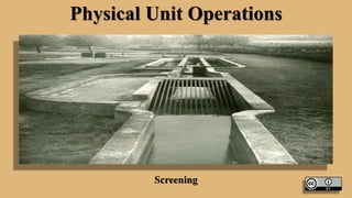
- 2. Screening • Screening is the first Unit Operation employed in wastewater treatment. Screening is necessary to retain floating matter and coarse solids as pieces of cloths garbage so as to protect pumps and other units from clogging. Thus retained material at screens is called as screenings. It is required to clean the screen for its proper functioning. A good Designer shall provide two screen units one as standby. Screens may consist of vertical or inclined bars (bar racks or bar screens), wire mesh or perforated plates having either circular or rectangular openings.
- 3. Screening
- 4. Screening
- 5. Screening • Screens are Kept ahead of grit chambers, Bar Screens are classified according to the spacing of bars as coarse screen ( Spacing ≥ 50 mm, Medium ( Opening 20 to 50 mm). Bar screen are inclined at 30 0C to 60 0C to the direction of flow to increase the area of screening. • Screens are fixed permanently and may either be manually cleaned or mechanically cleaned. The total amount of screening may be 0.03 to 0.08 m3/million litre of wastewater. • Screening can be disintegrated, digested, incinerated or buried.
- 6. Screening
- 7. Design Criteria for Bar Screens ( Bar Racks) Design Parameters Manually Cleaned Mechanically Cleaned 1. Velocity through Rack ( m/s) 0.3- 0.6 0.6- 1.0 2. Bar Size Width (mm) Depth (mm) 4-8 25-50 8-10 50-75 3. Spacing Between Bars (mm) 25-75 10-50 4. Slope from Horizontal Degrees 45-60 75-85 5. Allowable head loss in clogged condition mm 150 150
- 8. Design Criteria for Bar Screens ( Bar Racks) Head Loss through the bar rack is calculated from the following formulae. • HL= 𝑽 𝟐 −𝒗 𝟐 𝟐𝒈 𝟏 𝟎.𝟕 … … … … … … . . 𝟏 • = 0.0728 (V2- v2) • HL= 𝜷 𝑾 𝒃 𝟒 𝟑 Hv. Sinθ………………..(2) • Where, • HL= Head Loss through bar rack in meters • V= Velocity through Rack, m/s • v= Velocity in upstream of bar Rack, m/s • G= Acceleration due to Gravity • = 9.81 m/sec2
- 9. Design Criteria for Bar Screens ( Bar Racks) • W= Maximum Cross Sectional Width of bars facing the wastewater flow, meters • b= minimum clear bar spacing • Hv= Velocity head of wastewater flow approaching the bar in meters • β = Bar Shape factor Value of Bar Shape factor for Clean Bar Rack are Given Below • Sharp Edge Rectangular Bar- 2.42 • Rectangular with Semi circular faceing Upstream- 1.79 • Rectangular with both ends Semi-circular – 1.67 • Circular Bars – 1.83
- 10. Characteristics Quantity & Composition of Screenings • Quantity of Screenings depends upon the type of screen, weather, & Characteristics of wastewater. Narrow opening will collect more screenings & hot weather shall increase the use of water & Wastewater formation shall be more thereby increasing screenings. Quantity of screenings may be 0.03 to 0.08 m3/ ML with an average of around 0.05 m3/ML • Screening contain approximately 80 % moisture and has a normal wt. density of 960 kg/ m3. Screening are odorous and attract flies. Often screenings are sent to grinders where they are ground and returned to wastewater treatment plant.
- 11. Characteristics Quantity & Composition of Screenings
- 12. Design of BAR Screens Following Information are Required for design: • Peak Wet Weather flow. • Peak Dry Weather flow. • Hydraulic Design of Influent Conduit. • Treatment Plant Design Criteria Specified by Bureau of Indian Standards or other Recognized agency. • Equipment Manufacturers, their specifications for equipment. • Velocity through bars • Information on Existing facility if plant is to be expanded. • Bar Spacing and head loss constrained through the rack & Through entire plant. • Existing Site Plan with Contours. • Velocities through Screen Chamber.
- 13. Design Example • Design Bar Screen for a Peak flow of 50 MLD. Assume Other data, Maximum Rate of flow in m3/Sec • = 50 x 10 6 x 10-3 = 0.5787 m3/sec 24 x 60 x 60 Let Us Assume the velocity through the screen as 0.8 m/sec Net Area of Screen= 0.5787 0.8 = 0.7234 m 2
- 14. Design Example • Let us use bars of 10 mm x 50 mm with 10 mm dimensions facing the flow, at a spacing of 40 mm between the bars. So, • Gross Area = s + t Net Area s = Clear Spacing + Bar Thickness Clear Spacing Therefore, Gross area in our Case = Net Area x { Clear Spacing + Bar Thickness } Clear Spacing Gross Area = 0.7234 x 40 + 10 40 = 0.9043 Keep Screen at 45 0 Inclination with horizontal then Gross Area required = 0.9043 Sin 45 = 1.2788 m 2
- 15. Design Example • Velocity in the approach Channel i.e. Slightly Upstream of Bar Rack • = 0.8 x 40 50 = 0.64 m/sec Thus we have V= 0.8 m/sec v= 0.64 m/sec
- 16. Design Example • Therefore, • HL= 𝑽𝟐−𝒗𝟐 𝟐𝒈 𝟏 𝟎.𝟕 • = 0.0729 ( V2- v2) • = 0.0729 ( 0.8 2 – 0.64 2) • = 0.017 m • = 1.7 cm • This will be the head-loss when the screen is clean • If it is half Clogged.
- 17. Design Example • V= 2 x 0.8 • = 1.6 m/sec & • HL= 0.0729 ( 1.6 2 – 0.64 2) • = 0.157 m • = 15.7 cm • So to reduce the head loss frequently cleaning of screen is required.
- 18. References • Environmental Engineering : By Prof B.R.Shah Prof A M Malek • Internet Websites
- 19. Thanks …