Polkadot JAM Slides - Token2049 - By Dr. Gavin Wood
1Routing Basics.pdf
1. Routing Basics
Introduction
Routing
IPv4
Forwarding
Some definitions
Policy options
Routing Protocols
An internet is a combination of networks connected by routers. When a datagram goes from a source to a
destination, it will probably pass through many routers until it reaches the router attached to the destination
network.
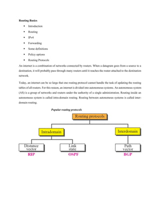
Today, an internet can be so large that one routing protocol cannot handle the task of updating the routing
tables of all routers. For this reason, an internet is divided into autonomous systems. An autonomous system
(AS) is a group of networks and routers under the authority of a single administration. Routing inside an
autonomous system is called intra-domain routing. Routing between autonomous systems is called inter-
domain routing.
Popular routing protocols
2. IPv4
Internet uses IPv4
Addresses are 32 bits long
Range from 1.0.0.0 to 223.255.255.255
0.0.0.0 to 0.255.255.255 and 224.0.0.0 to 255.255.255.255 have “special” uses
IPv4 address has a network portion and a host portion
Address and subnet mask
written as
12.34.56.78 255.255.255.0 or
12.34.56.78/24
mask represents the number of network bits in the 32 bit address
the remaining bits are the host bits
Routed Protocols
Routed protocols
Have packet headers that can contain Network layer addresses
Developed to support networks consisting of multiple networks or sub networks
Protocols that can carry Network layer information
Transmission Control Protocol/Internet Protocol (TCP/IP)
Internetwork Packet Exchange/Sequenced Packet Exchange (IPX/SPX)
Routing protocols
Protocols used by routers to make path determination choices and to share those choices
with other routers
Hop count
The number of routers a packet must pass through to reach a particular network
Metric
A value used to define the suitability of a particular route
Routers use metrics to determine which routes are better than other routes
The metrics may be distance, throughput, delay and error rat.
3. Autonomous system (AS)
Uses Interior Gateway Protocols as routing protocols
A group of routers under the control of a single administration
Interior Gateway Protocols (IGPs) are Routing protocols used within an AS
Exterior Gateway Protocols (EGPs)
o Routing protocols used to route information between multiple
autonomous systems
Examples of IGPs
o Routing Information Protocol (RIP)
o Interior Gateway Routing Protocol (IGRP)
o Enhanced Interior Gateway Routing Protocol (EIGRP)
o Open Shortest Path First (OSPF)
Example of EGP
o Border Gateway Protocol (BGP)
DISTANCE VECTOR ROUTING
Today, an internet can be so large that one routing protocol cannot handle the task of updating the routing
tables of all routers. For this reason, an internet is divided into autonomous systems. An
autonomous system (AS) is a group of networks and routers under the authority of a single
administration. Routing inside an autonomous system is called intra-domain routing. Routing between
autonomous systems is called inter-domain routing.
RIP (Routing information protocol)
The Routing Information Protocol (RIP) is an intra-domain (interior) routing protocol used inside an
autonomous system. It is a very simple protocol based on distance vector routing. RIP implements
distance vector routing directly with some considerations.
However, RIP is susceptible to all the problems normally associated with distance-vector routing
protocols.
RIP has a maximum hop count of 15.As a result, RIP does not work in large internetworks
RIPv2 vs. RIPv1
RIPv1 uses broadcasting to send RIP messages to every neighbors. Routers as well as
hosts receive the packets
RIPv2 uses the all-router multicast address to send the RIP messages only to RIP routers
in the network.
4. OSPF (OPEN SHORT PATH FIRST)
The Open Shortest Path First (OSPF) protocol is an intra-domain routing protocol based
on link state routing. Its domain is also an autonomous system.
Routing : path finding from one end to other. Which means determining the best path of router.
routing is carried out in router by consulting routing table.
Routing protocol
Goal: determine “good” path (sequence of routers) through network from source to destination.
Routing algorithm: algorithm that finds least-cost path.
Routing Table: Example
5. ROUTING PROTOCOLS
Objective
• Differentiate between non routable, routed, and routing protocols
• Define Interior Gateway Protocols, Exterior Gateway Protocols
Problems
• How do we build a routing system that can handle hundreds of thousands of networks and billions
of end nodes?
• How to enhance the functionalities of Internet?
Non routable Protocols
• In the early days of networking, networks were small collections of computers linked together
– For the purposes of sharing information and expensive peripherals
6. • Early networks were sometimes configured as peer-to-peer networks
– Computers communicate with and provide services to their “peers”
– All communication occurs on the same network segment
Routed Protocols
• Routed protocols
– Have packet headers that can contain Network layer addresses
– Developed to support networks consisting of multiple networks or subnetworks
• Protocols that can carry Network layer information
– Transmission Control Protocol/Internet Protocol (TCP/IP)
– Internetwork Packet Exchange/Sequenced Packet Exchange (IPX/SPX)
7. • For routed protocols to work on a network
– Every device must be configured with a unique IP or IPX address (logical address)
8. • Routing protocols
– Protocols used by routers to make path determination choices and to share those choices
with other routers
• Hop count
– The number of routers a packet must pass through to reach a particular network
• Metric
– A value used to define the suitability of a particular route
– Routers use metrics to determine which routes are better than other routes
Autonomous system (AS)
– Uses Interior Gateway Protocols as routing protocols
– A group of routers under the control of a single administration
• Interior Gateway Protocols (IGPs) are
– Routing protocols used within an AS
• Exterior Gateway Protocols (EGPs)
– Routing protocols used to route information between multiple autonomous systems
9. 1: How Does Routing Work?
MULTI-PROTOCOL LABEL SWITCHING
(MPLS)
Traditional IP Routing (Recap)
Choosing the next hop
Open Shortest Path First (OSPF) to populate the routing table
Route look up based on the IP address
Find the next router to which the packet has to be sent
Replace the layer 2 address
Each router performs these steps
Disadvantages
• Header analysis performed at each hop
• Increased demand on routers
• Utilizes the best available path
• Some congested links and some underutilized links!
Degradation of throughput
Long delays
More losses
• No QoS
No service differentiation
Not possible with connectionless protocols
10. Multiprotocol Label Switching (MPLS)
Multiprotocol Label Switching (MPLS): is a mechanism in high-performance telecommunication
networks that directs data from one network node to the next based on short path labels rather
than long network addresses, avoiding complex lookups in a routing table.
Need for MPLS
• Rapid growth of Internet
• New latency dependent applications
• Quality of Service (QoS)
Less time at the routers
• Traffic Engineering
Flexibility in routing packets
• Connection-oriented forwarding techniques with connectionless IP
Utilizes the IP header information to maintain interoperability with IP based networks
Decides on the path of a packet before sending it
11. MPLS Background:
• MPLS deals with integration of layer 2 and layer 3
Simplified connection-oriented forwarding of layer 2
Flexibility and scalability of layer 3 routing
• MPLS does not replace IP; it supplements IP
• Traffic can be marked, classified and explicitly routed
• QoS can be achieved through MPLS
MPLS Basics:
A Label Switched Path (LSP) is set up for each route
• A LSP for a particular packet P is a sequence of routers :
<R1, R2……….. Rn>
Edge routers :
– analyze the IP header to decide which LSP to use
– add a corresponding local Label Switched Path Identifier, in the form of a label
– forward the packet to the next hop
IP versus MPLS comparison
• Routing decisions
IP routing – based on destination IP address
Label switching – based on labels
• Entire IP header analysis
IP routing – performed at each hop of the packets path in the network
Label switching – performed only at the ingress router
• Support for unicast and multicast data
IP routing – requires special multicast routing and forwarding algorithms
Label switching – requires only one forwarding algorithm
12. Benefits of MPLS:
Five reasons to move to MPLS:
1. Cost savings
2. QOS enablement.
3. Improved performance.
4. Disaster recovery.
5. Future proofing the network.
The Primary Benefit of MPLS: Is to eliminate dependence data link layer like technology like: ATM
(Asynchronous transfer mode), Frame Relay, or Ethernet.
Key acronym
• MPLS – MultiProtocol Label Switching
• FEC – Forward Equivalence Class
• LER – Label Edge Router
13. • LSR – Label Switching Router
• LIB – Label Information Base
• LSP – Label Switched Path
• LDP – Label Distribution Protocol
Label Edge Router (LER)
• Can be an ATM switch or a router
• Ingress LER performs the following:
Receives the packet
Adds label
Forwards the packet into the MPLS domain
• Egress LER removes the label and delivers the packet
Label Switching Router (LSR)
• A router/switch that supports MPLS
• Can be an ATM switch + label switch controller
• Label swapping
14. Each LSR examines the label on top of the stack
Uses the Label Information Base (LIB) to decide the outgoing path and the outgoing label
Removes the old label and attaches the new label
Forwards the packet on the predetermined path
Label Switched Path(LSP)
• LSP defines the path through LSRs from ingress to egress router
• FEC is determined at the LER-ingress
• LSPs are unidirectional
15. • LSP might deviate from the IGP shortest path
Label
• A short, fixed length identifier (32 bits)
• Label represents bandwidth, IP address prefix, class of service (CoS) and soon
• Sent with each packet
• Local between two routers
• Can have different labels if entering from different routers
• One label for one FEC
• Decided by the downstream router
LSR binds a label to an FEC
It then informs the upstream LSR of the binding
16. SATELLITE OVER VIEW:
A satellite communication system is an efficient way to link multiple communication sites together.
A communications satellite is a microwave repeater station that permits two or more users with
appropriate earth stations to deliver or exchange information in various forms.
VSAT (very small aperture terminal): refers to the size of the antenna reflector.
It has out door unit(ODU), indoor unit(IDU) and IFL cable
ODU:
reflector
Transceiver (BUC and LNB)
IFL cable: is coax cable to connect IDU to ODU
IDU: Ethernet interface to LAN
VSAT components
Antenna
Feed
LNB
BUC
17. IF CABLE
Indirect Satellite Router
VSAT ANTENNA : the VSAT antenna enables reception and transmission of signal to and from the
satellite.
LNB (low noise block down converter): the low noise block down converter is the receiving element of
your satellite.
BUC (The block up converter): is the part of transmit chain of your VSAT.
FEED horn: The feed is part of both the receive and transmit chain of your VSAT.
IF CABLE: use coaxial cable to connect the BUC and LNB in the IDU (modulation and
demodulation par)
VSAT consists of:
1. Ground segment it is responsible for delivering user communication to the space segment.
2. Space segment (satellite) it is commonly used as a microwave repeater in the sky receive signal in a
given frequency and retransmit them back at a different frequency.
Micro wave communication
point to point Transmission
long range communication
Expensive
Optical fiber communication
use either glass or plastic to transfer a light signal
fastest communication method
most expensive
18. Two Stations on Earth want to communicate through radio frequency broadcast but are too far away to
use conventional means.
Uplink :- Earth station sends a transmission to the satellite.
Downlink :- Satellite Transponder converts the signal and sends it down to the second earth station.
Advantages of Satellite communication
Mobile or wireless communication
Wide area coverage, country
Independence from terrestrial infrastructure
Rapid installation of Ground networks
Low cost per added site
Uniform service characteristics
Total service from single provider
Excellent for broadcast transmission
Band width on demand
Very high reliability, all on board systems are redundant
19. Disadvantage of satellite communication
Launching cost.
Bandwidth is gradually becoming up in use
Larger propagation delay
Short life time (7 to 15)
Security, since satellite signals are broadcasted. Solved by using sophisticated encryption
technique or coding.
Fading, satellite signals operating at certain frequency ( such as Ku or Ka band) are
susceptible to signal weakening due to bad weather like rain or fog
Interference, Network operating at C-band are susceptible to terrestrial microwave
signals
Applications of satellites
Weather forecasting
Radio and TV broadcast
Military satellites
Navigation satellites
Global telephone
Connecting remote areas
Global mobile communication
What is VSAT?
VSAT stands for Very Small Aperture Terminal and refers to receive/transmit terminals
installed at dispersed sites connecting to a central hub via satellite using small diameter
antenna dishes
Is a micro-earth station that used the latest innovations in the field of satellite
communications to allow user’s access to reliable satellite communications.
An earthbound station used in satellite communications of data, voice and video signals
provide users with services comparable to large getaways and terrestrial networks, at
fraction of the cost.
A typical VSAT consists of communications equipment and a small antenna with a
diameter less than 3.8 meters.
20. Why are VSATs used?
General Internet access
• provide internet-based services to places where the local telecom company infrastructure is
nonexistent
Distance Education (e-Learning)
• to enable courses conducted in one location to be transmitted to several other locations
Telemedicine; to provide video
• provide video, voice and/or images from remote health outposts, clinics and centers
Telephony
• connect towns and villages
Videoconferencing
• live two-way video communications among two or more locations
Banking
• Most commonly to link remote bank branches, Automatic Teller Machines
(ATMs) and Points of Sale (POS) to the bank’s main branch or electronic
clearing network.
Virtual Private Networks (VPNS)
• Connected to headquarters via a VSAT network.
Media
• broadcasting live or relayed to television networks. This is often called
Satellite News Gathering or SNG.
Advantages of VSATs
Cost - effective
Easy Installation
Centrally managed Networks which reduces a lot of logistics cost for the customer
Satellite can deploy relatively fast to provide connectivity and coverage over a wide area
Coverage of rural and undeveloped region
Relative high data rate directly to user anywhere within the network
Broadcast/unicast/multicast capability
VSAT network interface with any type of communication network nodes, including
PSTN, public exchange, cellular telephone system
Disadvantage of VSATs
Latency, about 250 ms on single hop
21. Security, since satellite signals are broadcasted. Solved by using
sophisticated encryption technique or coding.
Fading, satellite signals operating at certain frequency (such as Ku or
Ka band) are susceptible to signal weakening due to bad weather like
rain or fog
Interference, Network operating at C-band are susceptible to terrestrial
microwave signals
When VSAT is Needed?
When uniquely VSAT make it attractive
When the cost lower than Terrestrial
When it is the only solution
For Example :
TV Broadcast
Offshore
Communication
Automatic Teller Machine
Rural Communication
What are the components of VSATs?
Antenna
The antenna is responsible for transmitting, the amplified signal from the power amplifier to the satellite
and also receiving the signal from the satellite in conjunction with the low noise amplifier.
22. Feed horn
is a part of Antenna. It plays a vital role in a VSAT system. It receives signal from the Satellite
reflected to Antenna and fed to the Indoor unit.
Power Amplifier:
The Power Amplifier is used for amplifying the Up converter RF signal before being fed into
the Antenna system.The Amplifier can be either Mounted on the Antenna system or
could be placed in the Indoor Rack. The amplification is required to send the up stream signals to
the Satellite.
Low Noise Amplifier:
The signal that travels from the satellite would have become weak due to various atmospheric
issues, the signal strength is reduced to a few watts hence the signal need to pass through an
equipment that will increase the signal strength from a few watts to several Kilowatts.
The low noise amplifier is responsible for amplifying very low power satellite signals received at
the antenna to a higher signal strength before it is fed into the down converter.
Down-Converter:
A down converter amplifies and converts the frequency (RF to IF), which is received from the
low noise amplifier. This is then passed on to the demodulator.
Up-Converter
An up-converter amplifies & converts the frequency (IF to RF), that is received from the
modulator. This is then passed on to the power amplifier for further amplification and
transmission.
Demodulator & Modulators:
– Demodulator is responsible for converting the IF signals into digital format.
– Modulators on the contrary are responsible for converting the digital data into IF signals.
23. What is VSAT HUB
A VSAT hub is a huge earth station that is responsible for controlling & monitoring all
the activities of the geographical spread of VSATs.
All the remote VSATs communicate to one central site, this Central Site is connected to
the hub, as the Hub is the switching element.
Network Topologies
physically laid out or configured in various ways
main network topologies
1. Broadcast
• one terminal transmitting the message and several terminals receiving the message
• receive only but not transmit
2. Point to point
Involves only two terminals communicating directly with each other over a dedicated channel.
Common applications include
• sending news reports from the field back to a central studio (Satellite News Gathering or SNG),
• providing telecommunication services to remote areas
• providing large amounts of bandwidth to Internet Service Providers.
3. Star
Hub spokes with several VSAT stations communicating through a central facility (the Hub) which
regulates and controls communications.
24. 4. Mash
VSAT terminals have the ability to communicate directly with one another without going
through a central Hub.
Referred to as “hub-less networks”.
Requires relatively larger and more sophisticated VSAT terminals and indoor equipment
which increases the start up costs. However,
It is ideal for real time communications
Basics of satellite
Communication is exchanging of information among peoples from one place to another .
Types of communication
Micro wave communication - point to point Transmission
Optical fiber communication - use either glass or plastic to transfer a light signal
- fastest communication method
Satellite communication
-sending (uplink)
- Receiving (Downlink)
- Amplifying signal
Satellite transmission:- - sending signals
-receive,
- amplify, and transmit back to earth
Satellite is a microwave device consists of receiver, repeater and regenerator in orbit
Space segment (Satellite)-
Microwave repeater in the sky
Receives uplink signals and then retransmit by decreasing the frequency of the signal
(down link) to any chosen geographic area on the surface of the earth.
Ground segment (Terminal or Earth Station) :- Deliver the user communications (uplink).
25. How do Satellites Work
Two Stations on Earth want to communicate through radio broadcast. But, are too far away to use
conventional means.
Use as a relay station
for two station communication
Uplink :- Station sends a transmission to the satellite.
Downlink :- Satellite Transponder converts the signal and sends it down to the second earth station.
Advantages of Satellites
The advantages of satellite communication over terrestrial communication
are:
26. The coverage area of a satellite greatly exceeds that of a terrestrial system.
Transmission cost of a satellite is independent of the distance from the
center of the coverage area.
Satellite to Satellite communication is very precise.
Service directly to user premises.
All user have same access possibilities.
Disadvantages of Satellites
The disadvantages of satellite communication:
Launching cost.
Bandwidth is gradually becoming used up.
Larger propagation delay
Short life time (7 to 15)
Security, since satellite signals are broadcasted. Solved by using sophisticated
encryption technique or coding.
Fading, satellite signals operating at certain frequency (such as Ku or Ka band) are
susceptible to signal weakening due to bad weather like rain or fog
Interference, Network operating at C-band are susceptible to terrestrial microwave
signals
Communication Satellite Orbits
Satellites circle the earth in orbits, balancing gravity against centripetal force.
27. Types of Satellite Orbits
GEO
Ease of tracking
Very large round trip signal delay
about 36,000kms
serves for data and communication broadcasting
Fixed in the sky relative to the earth’s surface and signal caver 42.2% of earth
surface.
LEO
High orbital speed
about 10,000kms
short round trip signal delay
serves for research and development
Voice and mobile
MEO
about 21,000kms
Mediate Launch cost
Small round trip signal delay
28. serves for voice and mobile
GEO Orbit
The orbit must be geosynchronous having an orbit period of 24 Hrs
The orbit must be a circle.
The orbit must be lie in the earth’s equatorial plan.
High power Amplifier
Amplify RF signal to transmission
has travel wave tube (TWT) amplifier
Wideband (Full spectrum) Greater than 500 MHz
Converter
Up Converter
Accepts the modulated IF carriers from modem and translate its intermediate frequency (IF) to the up
link RF frequency of the satellite.
Down Converter Receive the modulated RF carriers from the low noise amplifier(LNA)
and translate its down link RF frequency to the intermediate frequency (IF)
29. Satellite Modem
Modulate baseband signal into intermediate frequency spectrum, and demodulate
intermediate frequency signal to baseband signal.
Common uses of VSATs
General Internet access
– provide internet-based services to places where the local telecom company
infrastructure is nonexistent
Distance Education (e-Learning)
– to enable courses conducted in one location to be transmitted to several other locations
Telemedicine
– provide video, voice and/or images from remote health outposts, clinics and centers
Telephony
– connect towns and villages
Videoconferencing
– live two-way video communications among two or more locations
Banking
– Most commonly to link remote bank branches, Automatic Teller Machines (ATMs) and
Points of Sale (POS) to the bank’s main branch or electronic clearing network.
Virtual Private Networks (VPNS)
– Connected to headquarters via a VSAT network.
Media
– broadcasting live or relayed to television networks. This is often called Satellite News
Gathering or SNG.
When VSAT is Needed?
When the cost lower that of Terrestrial
When it is the only solution
For Example :
TV Broadcast
30. Data Communication
Automatic Teller Machine
Rural voice Communication
VSATs and How they Work
A VSAT is composed of a dish, technically referred to as an antenna, and a receive-transmit
assembly, called a feed assembly, attached to the dish.
This feed assembly is connected via one or two cables referred to as an Inter Facility Link (IFL)
to electronic equipment (In Door Unit or IDU) that processes the information (voice, video or
data) received or for transmission.
Reflector: - Receive and reflect signals to and from the satellites
LNB: - boost the weak received signals without amplifying the noise signals
BUC (HPA):- Amplifies and increases the frequency of the signal and then feeds it to
the feed horn
Ortho Mode Transducer (OMT) and the Transmit Reject filter
ensure that signals received and transmitted do not mix up and interfere with each
other.
IFL (inter facility link) Cable.
– It conveys the down converted signals from the LNB to the IDU and from the
IDU to the BUC
– Carries: DC power (for the ODU), Transmit and Receive IF signals,
Transmitter control signals, ODU status signals and Reference frequency
signal
31. Remote terminal LEDs
The terminal has five LED indicators on its front panel. They are described below.
LAN - indicates whether the LAN is connected and usable, and whether there is receive or
transmit activity.
Transmit - indicates whether the terminal can transmit, is transmitting, or if some
condition is preventing transmission.
Receive - indicates whether the terminal has acquired the correct outroute, is receiving, or
if some condition is preventing reception.
System - indicates whether the terminal is operational or not. This indicator steadily flashes
on a DW7700 when the DW7700 is connected through DIRECWAY Virtual Private
Network Automatic Dial Backup (DVADB).
Power - indicates whether the terminal is powered on and operating normally.
32. Front panel LEDs When the terminal is powered on and transmitting or receiving
data:
The LAN LED is on and blinks intermittently as
frames are transmitted or received.
The Transmit LED is on and blinks intermittently as
frames are transmitted.
The Receive LED is on and blinks intermittently as
frames are received.
The System LED is on. The indicator steadily flashes
on a DW7700 when the DW7700 is connected through
DVADB.
The Power LED is on.
Ethernet port LEDs The DW7000 has one RJ-45, 10/100BaseT Ethernet port. The
port has a green and a yellow LED. A flashing green LED
indicates a valid link between the DW7000 and Ethernet
device; a dark LED indicates an invalid link. An illuminated
yellow LED indicates the port is operating in 100BaseT mode;
a dark yellow LED indicates the port is operating in 10BaseT
mode. The Ethernet port and indicators are shown in Figure
below.
The Ethernet port supports a wide range of devices, including:
PCs equipped with Network Interface Cards
(NICs)
Hubs
Routers
Switches
33. HN7700S overview
The HN7700S figure below is a self-hosted remote terminal equipped with a serial port, two Ethernet
ports, and an internal modem (with telephone jack) to support the Virtual Private Network Automatic
Dial Backup (VADB) feature. VADB is designed for enterprise customers.
34. The HN7700S remote terminal includes features that make it an ideal broadband communications solution
for enterprise customers. These features are introduced below
• VADB – The HN7700S remote terminal includes an internal modem that supports the
Virtual Private Network Automatic Dial Backup (VADB) feature. VADB enables the
HN7700S to send and receive data over a terrestrial phone line if the satellite link between
the terminal and the Network Operations Center (NOC) should fail or degrade below an
acceptable threshold.
• Serial port – Enables you to connect the terminal to a serial device such as a point of sale
(POS) terminal, credit verification device, or automated teller machine (ATM).
• Dual Ethernet ports – Provides the ability to connect two Ethernet devices to the terminal.
Supported devices include PCs equipped with network interface cards (NICs), hubs, routers,
switches, the Hughes Voice Appliance, and Hughes serial appliances. A Hughes serial
appliance can support up to four serial devices.
• Port forwarding – Allows servers on your LAN to receive specific Transmission Control
Protocol (TCP) and User Datagram Protocol (UDP) traffic from the Internet.
• To support the VADB feature, an RJ-11 telephone cable connects the HN7700S
to a phone jack. (In some countries, a converter may be required to connect the cable
to the phone jack.)
35. IP ADDRESS VERIFICATION
10.0.11.152 Mobile networking
10.0.11.153 Mobile networking
10.0.11.154 Mobile networking
10.0.11.169/170 Mobile networking
10.0.11.174 Mobile networking
10.0.4.167 IP SWITCHING(MSAG)
10.0.4.168 IPN SWITCHING(MSAG)
10.7.7.230
10.7.7.246
10.7.7.238
10.7.7.110
10.0.7.170
36. How to configure Remote ?
Step 1: Change the ip address of your laptop or select automatic obtain
Ip-192.168.0.2
Subnet-255.255.255.252
Gateway-192.168.0.1
Step 2: connect the LAN cable to the IDU LAN 1 port.
Step 3: telnet 192.168.0.1 1953
Step 4: select a (enter)
Step 5 : Enter all the parameter
37. Step6. The entered parameter will be given from HUB.
Step 7: Check whether receive is locked or not. IF not locked.
Step 8: upload the sbc.cfg file
E1 standard
E1 is the European format for digital transmission. E1 carry signals at 2.048 mbps. Each signal has 32
channels, and each transmit at 64 kbps. Mathematically, 32channel * 64kbps = 2,048 kbps = 2.048 mbps.
The STM-1(synchronous tra
nsport module level-1) is the SDH ITU fiber optical network transmission standard. It has a bit rate of
155.52 Mbps.The STM-1 MUX multiplexes 63 E1 signal in to STM-1 stream.
IPoEv4 Service
subscribers obtain IP addresses through DHCP. Implies, DHCP is used to assign IP address to subscribers.
38. M6000-S works as a DHCP server that is responsible for assigning IP addresses. M6000-S Works
as a DHCP relay that is responsible for forwarding packets
Router definition(1)
Router : A kind of computer device used to interconnect networks.
Router must have the following features:
Multiple network layer interfaces to interconnect different networks
Implement the protocols up to the network layer
Have the function of storing, forwarding, path-finding.
Router functions (2)
The core function of router is interconnecting networks and data forwarding.
– Routing: - building route table and refreshing
– Switching: - forwarding packet between networks.
– Insulate broadcast packets, define access rule.
– Connecting different kinds of networks.
– Rate adapting between networks.
Router working principle
Routing function:-Study and exchange the network topology information or route information, Produce
and maintain route table.
Forwarding function:- Data transferring and processing procedure. (Receiving data on one interface,
then choose an appropriate interface to send it out, including the work of frame encapsulation and
decapsulation)
Routing function
The functions of routing is to create and maintain route table, make it ready for the LMP check in
the forwarding process.
It requires several basic steps:
What kind of protocols to route?
Is the destination network address in the route table?
What is the next hop address?
Which interface to send out the packet?
39. Route table
The information that router need to forward data is stored in a table, called route table. Router
checks the destination address of the packet, and chooses the next hop based on the information in
route table. Route table is stored in RAM.