1. 1. Introduction to Fundamentals
1.1 What is Remote Sensing?
So, what exactly is remote sensing? For the purposes of this tutorial, we will use the
following definition:
"Remote sensing is the science (and to some extent, art) of acquiring
information about the Earth's surface without actually being in contact
with it. This is done by sensing and recording reflected or emitted energy
and processing, analyzing, and applying that information."
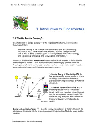
In much of remote sensing, the process involves an interaction between incident radiation
and the targets of interest. This is exemplified by the use of imaging systems where the
following seven elements are involved. Note, however that remote sensing also involves the
sensing of emitted energy and the use of non-imaging sensors.
1. Energy Source or Illumination (A) - the
first requirement for remote sensing is to have
an energy source which illuminates or
provides electromagnetic energy to the target
of interest.
2. Radiation and the Atmosphere (B) - as
the energy travels from its source to the
target, it will come in contact with and interact
with the atmosphere it passes through. This
interaction may take place a second time as
the energy travels from the target to the
sensor.
3. Interaction with the Target (C) - once the energy makes its way to the target through the
atmosphere, it interacts with the target depending on the properties of both the target and the
radiation.
Page 5Section 1.1 What is Remote Sensing?
Canada Centre for Remote Sensing
2. 4. Recording of Energy by the Sensor (D) - after the energy has been scattered by, or
emitted from the target, we require a sensor (remote - not in contact with the target) to collect
and record the electromagnetic radiation.
5. Transmission, Reception, and Processing (E) - the energy recorded by the sensor has
to be transmitted, often in electronic form, to a receiving and processing station where the
data are processed into an image (hardcopy and/or digital).
6. Interpretation and Analysis (F) - the processed image is interpreted, visually and/or
digitally or electronically, to extract information about the target which was illuminated.
7. Application (G) - the final element of the remote sensing process is achieved when we
apply the information we have been able to extract from the imagery about the target in order
to better understand it, reveal some new information, or assist in solving a particular problem.
These seven elements comprise the remote sensing process from beginning to end. We will
be covering all of these in sequential order throughout the five chapters of this tutorial,
building upon the information learned as we go. Enjoy the journey!
Page 6Section 1.1 What is Remote Sensing?
Canada Centre for Remote Sensing
3. 1.2 Electromagnetic Radiation
As was noted in the previous section, the first
requirement for remote sensing is to have an
energy source to illuminate the target
(unless the sensed energy is being emitted by
the target). This energy is in the form of
electromagnetic radiation.
All electromagnetic radiation has fundamental
properties and behaves in predictable ways
according to the basics of wave theory.
Electromagnetic radiation consists of an
electrical field(E) which varies in magnitude in
a direction perpendicular to the direction in
which the radiation is traveling, and a
magnetic field (M) oriented at right angles to
the electrical field. Both these fields travel at
the speed of light (c).
Two characteristics of electromagnetic
radiation are particularly important for understanding remote sensing. These are the
wavelength and frequency.
Page 7Section 1.2 Electromagnetic Radiation
Canada Centre for Remote Sensing
4. The wavelength is the length of one wave cycle, which can be measured as the distance
between successive wave crests. Wavelength is usually represented by the Greek letter
lambda (λ). Wavelength is measured in metres (m) or some factor of metres such as
nanometres (nm, 10-9 metres), micrometres (µm, 10-6 metres) (µm, 10-6 metres) or
centimetres (cm, 10-2 metres). Frequency refers to the number of cycles of a wave passing a
fixed point per unit of time. Frequency is normally measured in hertz (Hz), equivalent to one
cycle per second, and various multiples of hertz.
Wavelength and frequency are related by the following formula:
Therefore, the two are inversely related to each other. The shorter the wavelength, the higher
the frequency. The longer the wavelength, the lower the frequency. Understanding the
characteristics of electromagnetic radiation in terms of their wavelength and frequency is
crucial to understanding the information to be extracted from remote sensing data. Next we
will be examining the way in which we categorize electromagnetic radiation for just that
purpose.
Page 8Section 1.2 Electromagnetic Radiation
Canada Centre for Remote Sensing
5. 1.3 The Electromagnetic Spectrum
The electromagnetic spectrum ranges from the shorter wavelengths (including gamma and
x-rays) to the longer wavelengths (including microwaves and broadcast radio waves). There
are several regions of the electromagnetic spectrum which are useful for remote sensing.
For most purposes, the ultraviolet or UV
portion of the spectrum has the shortest
wavelengths which are practical for remote
sensing. This radiation is just beyond the
violet portion of the visible wavelengths,
hence its name. Some Earth surface
materials, primarily rocks and minerals,
fluoresce or emit visible light when illuminated
by UV radiation.
Page 9Section 1.3 The Electromagnetic Spectrum
Canada Centre for Remote Sensing
6. The light which our eyes - our "remote
sensors" - can detect is part of the visible
spectrum. It is important to recognize how
small the visible portion is relative to the rest
of the spectrum. There is a lot of radiation
around us which is "invisible" to our eyes, but
can be detected by other remote sensing
instruments and used to our advantage. The
visible wavelengths cover a range from
approximately 0.4 to 0.7 µm. The longest
visible wavelength is red and the shortest is
violet. Common wavelengths of what we
perceive as particular colours from the visible
portion of the spectrum are listed below. It is
important to note that this is the only portion
of the spectrum we can associate with the
concept of colours.
Violet: 0.4 - 0.446 µm
Blue: 0.446 - 0.500 µm
Green: 0.500 - 0.578 µm
Yellow: 0.578 - 0.592 µm
Orange: 0.592 - 0.620 µm
Red: 0.620 - 0.7 µm
Blue, green, and red are the primary
colours or wavelengths of the visible
spectrum. They are defined as such because
no single primary colour can be created from
the other two, but all other colours can be
formed by combining blue, green, and red in
various proportions. Although we see sunlight
as a uniform or homogeneous colour, it is
actually composed of various wavelengths of
radiation in primarily the ultraviolet, visible
and infrared portions of the spectrum. The visible portion of this radiation can be shown in its
Page 10Section 1.3 The Electromagnetic Spectrum
Canada Centre for Remote Sensing
7. component colours when sunlight is passed through a prism, which bends the light in differing
amounts according to wavelength.
The next portion of the spectrum of interest is
the infrared (IR) region which covers the
wavelength range from approximately 0.7 µm
to 100 µm - more than 100 times as wide as
the visible portion! The infrared region can be
divided into two categories based on their
radiation properties - the reflected IR, and
the emitted or thermal IR. Radiation in the
reflected IR region is used for remote sensing
purposes in ways very similar to radiation in
the visible portion. The reflected IR covers
wavelengths from approximately 0.7 µm to
3.0 µm. The thermal IR region is quite
different than the visible and reflected IR
portions, as this energy is essentially the
radiation that is emitted from the Earth's
surface in the form of heat. The thermal IR
covers wavelengths from approximately 3.0
µm to 100 µm.
The portion of the spectrum of more recent
interest to remote sensing is the microwave
region from about 1 mm to 1 m. This covers
the longest wavelengths used for remote
sensing. The shorter wavelengths have
properties similar to the thermal infrared
region while the longer wavelengths approach
the wavelengths used for radio broadcasts.
Because of the special nature of this region
and its importance to remote sensing in
Canada, an entire chapter (Chapter 3) of the
tutorial is dedicated to microwave sensing.
Page 11Section 1.3 The Electromagnetic Spectrum
Canada Centre for Remote Sensing
8. 1.4 Interactions with the Atmosphere
Before radiation used for remote sensing reaches the Earth's surface it has to travel through
some distance of the Earth's atmosphere. Particles and gases in the atmosphere can affect
the incoming light and radiation. These effects are caused by the mechanisms of scattering
and absorption.
Scattering occurs when particles or large gas molecules present in the atmosphere interact
with and cause the electromagnetic radiation to be redirected from its original path. How much
scattering takes place depends on several factors including the wavelength of the radiation,
the abundance of particles or gases, and the distance the radiation travels through the
atmosphere. There are three (3) types of scattering which take place.
Page 12Section 1.4 Interactions with the Atmosphere
Canada Centre for Remote Sensing
9. Rayleigh scattering occurs when particles are very small compared to the wavelength of the
radiation. These could be particles such as small specks of dust or nitrogen and oxygen
molecules. Rayleigh scattering causes shorter wavelengths of energy to be scattered much
more than longer wavelengths. Rayleigh scattering is the dominant scattering mechanism in
the upper atmosphere. The fact that the sky appears "blue" during the day is because of this
phenomenon. As sunlight passes through the atmosphere, the shorter wavelengths (i.e. blue)
of the visible spectrum are scattered more than the other (longer) visible wavelengths. At
sunrise and sunset the light has to travel farther through the atmosphere than at midday and
the scattering of the shorter wavelengths is more complete; this leaves a greater proportion of
the longer wavelengths to penetrate the atmosphere.
Mie scattering occurs when the particles are just about the same size as the wavelength of
the radiation. Dust, pollen, smoke and water vapour are common causes of Mie scattering
which tends to affect longer wavelengths than those affected by Rayleigh scattering. Mie
scattering occurs mostly in the lower portions of the atmosphere where larger particles are
more abundant, and dominates when cloud conditions are overcast.
The final scattering mechanism of importance is
called nonselective scattering. This occurs when
the particles are much larger than the wavelength of
the radiation. Water droplets and large dust
particles can cause this type of scattering.
Nonselective scattering gets its name from the fact
that all wavelengths are scattered about equally.
This type of scattering causes fog and clouds to
appear white to our eyes because blue, green, and
red light are all scattered in approximately equal
quantities (blue+green+red light = white light).
Page 13Section 1.4 Interactions with the Atmosphere
Canada Centre for Remote Sensing
10. Absorption is the other main mechanism at work
when electromagnetic radiation interacts with the
atmosphere. In contrast to scattering, this
phenomenon causes molecules in the atmosphere to
absorb energy at various wavelengths. Ozone,
carbon dioxide, and water vapour are the three main
atmospheric constituents which absorb radiation.
Ozone serves to absorb the harmful (to most living
things) ultraviolet radiation from the sun. Without this
protective layer in the atmosphere our skin would
burn when exposed to sunlight.
You may have heard carbon dioxide referred to as
a greenhouse gas. This is because it tends to absorb radiation strongly in the far infrared
portion of the spectrum - that area associated with thermal heating - which serves to trap this
heat inside the atmosphere. Water vapour in the atmosphere absorbs much of the incoming
longwave infrared and shortwave microwave radiation (between 22µm and 1m). The
presence of water vapour in the lower atmosphere varies greatly from location to location and
at different times of the year. For example, the air mass above a desert would have very little
water vapour to absorb energy, while the tropics would have high concentrations of water
vapour (i.e. high humidity).
Because these gases absorb
electromagnetic energy in very
specific regions of the spectrum, they
influence where (in the spectrum) we
can "look" for remote sensing
purposes. Those areas of the
spectrum which are not severely
influenced by atmospheric absorption
and thus, are useful to remote
sensors, are called atmospheric
windows. By comparing the
characteristics of the two most
common energy/radiation sources
(the sun and the earth) with the
atmospheric windows available to us, we can define those wavelengths that we can
use most effectively for remote sensing. The visible portion of the spectrum, to
which our eyes are most sensitive, corresponds to both an atmospheric window and
the peak energy level of the sun. Note also that heat energy emitted by the Earth
corresponds to a window around 10 µm in the thermal IR portion of the spectrum,
while the large window at wavelengths beyond 1 mm is associated with the
Page 14Section 1.4 Interactions with the Atmosphere
Canada Centre for Remote Sensing
11. microwave region.
Now that we understand how electromagnetic energy makes its journey from its source to the
surface (and it is a difficult journey, as you can see) we will next examine what happens to
that radiation when it does arrive at the Earth's surface.
Page 15Section 1.4 Interactions with the Atmosphere
Canada Centre for Remote Sensing
12. 1.5 Radiation - Target Interactions
Radiation that is not absorbed or scattered in
the atmosphere can reach and interact with
the Earth's surface. There are three (3) forms
of interaction that can take place when energy
strikes, or is incident (I) upon the surface.
These are: absorption (A); transmission
(T); and reflection (R). The total incident
energy will interact with the surface in one or
more of these three ways. The proportions of
each will depend on the wavelength of the
energy and the material and condition of the
feature.
Absorption (A) occurs when radiation (energy) is absorbed into the target while transmission
(T) occurs when radiation passes through a target. Reflection (R) occurs when radiation
"bounces" off the target and is redirected. In remote sensing, we are most interested in
measuring the radiation reflected from targets. We refer to two types of reflection, which
represent the two extreme ends of the way in which energy is reflected from a target:
specular reflection and diffuse reflection.
Page 16Section 1.5 Radiation - Target Interactions
Canada Centre for Remote Sensing
13. When a surface is smooth we get specular or mirror-like reflection where all (or almost all) of
the energy is directed away from the surface in a single direction. Diffuse reflection occurs
when the surface is rough and the energy is reflected almost uniformly in all directions. Most
earth surface features lie somewhere between perfectly specular or perfectly diffuse
reflectors. Whether a particular target reflects specularly or diffusely, or somewhere in
between, depends on the surface roughness of the feature in comparison to the wavelength of
the incoming radiation. If the wavelengths are much smaller than the surface variations or the
particle sizes that make up the surface, diffuse reflection will dominate. For example, fine-
grained sand would appear fairly smooth to long wavelength microwaves but would appear
quite rough to the visible wavelengths.
Let's take a look at a couple of examples of targets at the Earth's surface and how energy at
the visible and infrared wavelengths interacts with them.
Leaves: A chemical compound in leaves
called chlorophyll strongly absorbs
radiation in the red and blue
wavelengths but reflects green
wavelengths. Leaves appear "greenest"
to us in the summer, when chlorophyll
content is at its maximum. In autumn,
there is less chlorophyll in the leaves, so
there is less absorption and
proportionately more reflection of the red
wavelengths, making the leaves appear
red or yellow (yellow is a combination of
red and green wavelengths). The
internal structure of healthy leaves act as excellent diffuse reflectors of near-infrared
wavelengths. If our eyes were sensitive to near-infrared, trees would appear extremely bright
to us at these wavelengths. In fact, measuring and monitoring the near-IR reflectance is one
way that scientists can determine how healthy (or unhealthy) vegetation may be.
Water: Longer wavelength visible and near
infrared radiation is absorbed more by water
than shorter visible wavelengths. Thus water
typically looks blue or blue-green due to
stronger reflectance at these shorter
wavelengths, and darker if viewed at red or
near infrared wavelengths. If there is
suspended sediment present in the upper
layers of the water body, then this will allow
better reflectivity and a brighter appearance
of the water. The apparent colour of the
water will show a slight shift to longer
Page 17Section 1.5 Radiation - Target Interactions
Canada Centre for Remote Sensing
14. wavelengths. Suspended sediment (S) can
be easily confused with shallow (but clear) water, since these two phenomena appear very
similar. Chlorophyll in algae absorbs more of the blue wavelengths and reflects the green,
making the water appear more green in colour when algae is present. The topography of the
water surface (rough, smooth, floating materials, etc.) can also lead to complications for
water-related interpretation due to potential problems of specular reflection and other
influences on colour and brightness.
We can see from these examples that, depending on the complex make-up of the target that
is being looked at, and the wavelengths of radiation involved, we can observe very different
responses to the mechanisms of absorption, transmission, and reflection. By measuring the
energy that is reflected (or emitted) by targets on the Earth's surface over a variety of different
wavelengths, we can build up a spectral response for that object. By comparing the
response patterns of different features we may be able to distinguish between them, where
we might not be able to, if we only compared them at one wavelength. For example, water
and vegetation may reflect somewhat similarly in the visible wavelengths but are almost
always separable in the infrared. Spectral response can be quite variable, even for the same
target type, and can also vary with time (e.g. "green-ness" of leaves) and location. Knowing
where to "look" spectrally and understanding the factors which influence the spectral response
of the features of interest are critical to correctly interpreting the interaction of electromagnetic
radiation with the surface.
Page 18Section 1.5 Radiation - Target Interactions
Canada Centre for Remote Sensing
15. 1.6 Passive vs. Active Sensing
So far, throughout this chapter, we have made
various references to the sun as a source of
energy or radiation. The sun provides a very
convenient source of energy for remote sensing.
The sun's energy is either reflected, as it is for
visible wavelengths, or absorbed and then re-
emitted, as it is for thermal infrared
wavelengths. Remote sensing systems which
measure energy that is naturally available are
called passive sensors. Passive sensors can
only be used to detect energy when the naturally
occurring energy is available. For all reflected
energy, this can only take place during the time
when the sun is illuminating the Earth. There is
no reflected energy available from the sun at night. Energy that is naturally emitted (such as
thermal infrared) can be detected day or night, as long as the amount of energy is large
enough to be recorded.
Active sensors, on the other hand, provide their own
energy source for illumination. The sensor emits radiation
which is directed toward the target to be investigated. The
radiation reflected from that target is detected and
measured by the sensor. Advantages for active sensors
include the ability to obtain measurements anytime,
regardless of the time of day or season. Active sensors can
be used for examining wavelengths that are not sufficiently
provided by the sun, such as microwaves, or to better
control the way a target is illuminated. However, active
systems require the generation of a fairly large amount of
energy to adequately illuminate targets. Some examples of
active sensors are a laser fluorosensor and a synthetic
aperture radar (SAR).
Page 19Section 1.6 Passive vs. Active Sensing
Canada Centre for Remote Sensing
16. 6
Types of Remote Sensing System
1- Visual remote sensing system
The human visual system is an example of a
remote sensing system in the general sense. The
sensors in this example are the two types of
photosensitive cells, known as the cones and
the rods, at the retina of the eyes. The cones are
responsible for colour vision. There are three
types of cones, each being sensitive to one of the red, green, and blue regions of
the visible spectrum. Thus, it is not coincidental that the modern computer
display monitors make use of the same three primary colours to generate a
multitude of colours for displaying colour images. The cones are insensitive
17. 7
under low light illumination condition, when their jobs are taken over by the
rods. The rods are sensitive only to the total light intensity. Hence, everything
appears in shades of grey when there is insufficient light. As the objects/events
being observed are located far away from the eyes, the information needs a
carrier to travel from the object to the eyes. In this case, the information carrier
is the visible light, a part of the electromagnetic spectrum. The objects
reflect/scatter the ambient light falling onto them. Part of the scattered light is
intercepted by the eyes, forming an image on the retina after passing through the
optical system of the eyes. The signals generated at the retina are carried via the
nerve fibres to the brain, the central processing unit (CPU) of the visual system.
These signals are processed and interpreted at the brain, with the aid of previous
experiences. The visual system is an example of a "Passive Remote Sensing"
system which depends on an external source of energy to operate. We all know
that this system won't work in darkness.
2- Optical Remote Sensing
In Optical Remote Sensing, optical sensors detect
solar radiation reflected or scattered from the
earth, forming images resembling photographs
taken by a camera high up in space. The
wavelength region usually extends from the
visible and near infrared VNIR to the short-wave
infrared SWIR. Different materials such as water, soil, vegetation, buildings and
roads reflect visible and infrared light in different ways. They have different
colours and brightness when seen under the sun. The interpretations of optical
images requires the knowledge of the spectral reflectance signatures of the
various materials (natural or man-made) covering the surface of the earth.
18. 8
3-Infrared Remote Sensing
Infrared remote sensing makes use of infrared sensors to detect infrared
radiation emitted from the Earth's surface. The middle-wave infrared (MWIR)
and long-wave infrared (LWIR) are within the thermal infrared region. These
radiations are emitted from warm objects such as the Earth's surface. They are
used in satellite remote sensing for measurements of the earth's land and sea
surface temperature. Thermal infrared remote sensing is also often used for
detection of forest fires, volcanoes, oil fires.
4-Microwave Remote Sensing
There are some remote sensing satellites which carry
passive or active microwave sensors. The active
sensors emit pulses of microwave radiation to
illuminate the areas to be imaged. Images of the
earth surface are formed by measuring the
microwave energy scattered by the ground or sea
back to the sensors. These satellites carry their own "flashlight" emitting
microwaves to illuminate their targets. The images can thus be acquired day
19. 9
and night. Microwaves have an additional advantage as they can penetrate clouds.
Images can be acquired even when there are clouds covering the earth surface. A
microwave imaging system which can produce high resolution image of the Earth
is the synthetic aperture radar (SAR). Electromagnetic radiation in the
microwave wavelength region is used in remote sensing to provide useful
information about the Earth's atmosphere, land and ocean. When microwaves
strike a surface, the proportion of energy scattered back to the sensor depends
on many factors:
Physical factors such as the dielectric constant of the surface materials
which also depends strongly on the moisture content;
Geometric factors such as surface roughness, slopes, orientation of the
objects relative to the radar beam direction;
The types of landcover (soil, vegetation or man-made objects).
Microwave frequency, polarisation and incident angle.
5-Radar Remote Sensing
Using radar, geographers can effectively map out
the terrain of a territory. Radar works by sending
out radio signals, and then waiting for them to
bounce off the ground and return. By measuring the
amount of time it takes for the signals to return, it is
possible to create a very accurate topographic map.
An important advantage to using radar is that it can penetrate thick clouds and
moisture. This allows scientists to accurately map areas such as rain forests,
which are otherwise too obscured by clouds and rain. Imaging radar systems are
versatile sources of remotely sensed images, providing daynight, all-weather
imaging capability. Radar images are used to map landforms and geologic
structure, soil types, vegetation and crops, and ice and oil slicks on the ocean
surface.
20. 10
Synthetic Aperture Radar (SAR)
In synthetic aperture radar (SAR) imaging, microwave pulses are transmitted by
an antenna towards the earth surface. The microwave energy scattered back to
the spacecraft is measured. The SAR makes use of the radar principle to form
an image by utilising the time delay of the backscattered signals. In real aperture
radar imaging, the ground resolution is limited by the size of the microwave
beam sent out from the antenna.
6-Satellite Remote Sensing
In this, you will see many remote sensing images
acquired by earth observation satellites. These
remote sensing satellites are equipped with
sensors looking down to the earth. They are the
"eyes in the sky" constantly observing the earth as
they go round in predictable orbits. Orbital
platforms collect and transmit data from different
parts of the electromagnetic spectrum, which in
conjunction with larger scale aerial or ground-based sensing and analysis
provides researchers with enough information to monitor trends. Other uses
include different areas of the earth sciences such as natural resource
management, agricultural fields such as land usage and conservation, and
national security and overhead, ground-based and stand-off collection on border
areas.
21. 11
How Satellites Acquire Images
Satellite sensors record the intensity of electromagnetic radiation (sunlight)
reflected from the earth at different wavelengths. Energy that is not reflected by
an object is absorbed. Each object has its own unique 'spectrum', some of which
are shown in the diagram below.
Remote sensing relies on the fact that particular features of the landscape such
as bush, crop, salt-affected land and water reflect light differently in different
wavelengths. Grass looks green, for example, because it reflects green light and
absorbs other visible wavelengths. This can be seen as a peak in the green band
in the reflectance spectrum for green grass above. The spectrum also shows that
grass reflects even more strongly in the infrared part of the spectrum. While this
can't be detected by the human eye, it can be detected by an infrared sensor.
Instruments mounted on satellites detect and record the energy that has been
reflected. The detectors are sensitive to particular ranges of wavelengths, called
'bands'. The satellite systems are characterised by the bands at which they
measure the reflected energy. The Landsat TM satellite, which provides the data
used in this project, has bands at the blue, green and red wavelengths in the
visible part of the spectrum and at three bands in the near and mid infrared part
of the spectrum and one band in the thermal infrared part of the spectrum. The
satellite detectors measure the intensity of the reflected energy and record it.
22. 12
7- Airborne Remote Sensing
In airborne remote sensing, downward or sideward
looking sensors are mounted on an aircraft to obtain
images of the earth's surface. An advantage of
airborne remote sensing, compared to satellite
remote sensing, is the capability of offering very
high spatial resolution images (20 cm or less). The
disadvantages are low coverage area and high cost
per unit area of ground coverage. It is not cost-effective to map a large area
using an airborne remote sensing system. Airborne remote sensing missions are
often carried out as one-time operations, whereas earth observation satellites
offer the possibility of continuous monitoring of the earth.
8-Acoustic and near-acoustic remote sensing
Sonar: passive sonar, listening for the sound made
by another object (a vessel, a whale etc); active
sonar, emitting pulses of sounds and listening
for echoes, used for detecting, ranging and
measurements of underwater objects and terrain.
Seismograms taken at different locations can locate and measure
earthquakes (after they occur) by comparing the relative intensity and
precise timing.
25. Urban & Regional Planning
• Mapping & updation of
city/town maps
• Urban sprawl monitoring
• Town planning
• Facility management
• GIS database development
Scope
Lyari Express Way – Section (Essa Nagri)
• Better decision support,
planning & management
• Rapid information updation
• Infrastructure development
monitoring
• Spatial information analysis
Benefits
26. Examples of hydrological applications include: ·
.wetlands mapping and monitoring, ·
.soil moisture estimation, ·
· determining snow-water equivalent, ·
. river and lake ice monitoring, ·
. flood mapping and monitoring, ·
.glacier dynamics monitoring (surges, ablation)
.river /delta change detection ·
.drainage basin mapping and watershed modelling ·
.irrigation canal leakage detection ·
. irrigation scheduling
27. Landuse / Landcover Mapping
• Monitoring dynamic changes
• Urban/Rural infrastructure
• Waterlogging & salinity
Scope
• Assessment of spatial distribution
of land resources
• Infrastructure monitoring
• Availability of usable land
• Future planning for better land
management for socio-economic
development
Benefits
29. Importance of remote
sensing
Remote Sensing allows data in locations that may be
inaccessible or too large for in situ approaches
Interplanetary studies are an excellent example of where remote
sensing is useful
• Sample and return missions are expensive and difficult
• Apollo missions were last fully successful sample and return missions
(Genesis was partially successful)
• Still, remote sensing was critical even in those missions to determine
where best to sample
Meteorological applications
• Probably the clearest example with the widest audience and daily impact
• Meteorological satellites cover large areas that are inaccessible
• Can cover these areas repeatedly to look for changes over time
National Defense
Resource Mapping
30. Advantages and Limitations of
Remote Sensing
The major advantages of remote sensing over the ground - based
methods are:
1.Synoptic view: Remote sensing process facilitates the study
of various features of earth's surface in their spatial relation to
each other and helps to delineate the required features and
phenomenon.
2.Accessibility: Remote sensing process makes it possible to
gather information about the inaccessible area when it is not
possible to do ground survey like in mountainous areas or
foreign lands.
3.Time: Since information about a large area can be gathered
quickly, the techniques save time and efforts of human beings/
or mass.
4.Multi-disciplinary applications: The data gathered by remote
sensing process can be used by the users of different
disciplines
like, geology, forestry land use etc.
31. Limitations of Remote Sensing Technology
1. Since resolution of the data from LISS-III is 23.5 M
the linear forest cover along roads, canals, bunds, rail of the
width less than the resolution are generally not be recorded.
2. young plantations and species having less chlorophyll
contents in their crown do not give proper reflectance and as
a result are difficult to be interpreted correctly.
3. considerable details on ground may be obscured in areas
having clouds and shadows. It is difficult to interpret such
areas without the help of collateral data.
4. variation in spectral reflectance during leaf less period
poses problems in interpretation.
5. gregarious occurrence of bushy vegetation, such as
lantana, sugarcane etc, often poses problems in delineation
of forest cover, as their reflectance is similar to that of tree
canopy.