SlideShare una empresa de Scribd logo
1 de 18
Operating system

         For a computer to be able to operate a computer programme (sometimes known as application or software),
the machine must be able to perform a certain number of preparatory operations to ensure exchange between the
processor, the memory and the physical resources (peripherals).
         The operating system (sometimes referred to by its abbreviation OS), is responsible for creating the link
between the material resources, the user and the applications (word processor, video game, etc.). When a programme
wants to access a material resource, it does not need to send specific information to the peripheral device but it simply
sends the information to the operating system, which conveys it to the relevant peripheral via its driver. If there are no
drivers, each programme has to recognise and take into account the communication with each type of peripheral!


       The operating system thus allows the "dissociation" of programmes and hardware, mainly to simplify resource
management and offer the user a simplified Man-machine interface (MMI) to overcome the complexity of the actual
machine.

Serial processing
         The earliest computer system has no OS at all, and is characterized as serial processing because users have to
reserve time slots in advance, and during the alloted period, they occupy the computer exclusively. Thus the computer
will be used in sequence by different users.
         These early systems presented two major problems:

1. Users may finish their tasks earlier than you have expected, and unfortunately the rest time is simply wasted. Or they
may run into problems, cannot finish in the allotted time, and thus are forced to stop, which causes much inconvenience
and delays the development.

2. In such systems, programs are presented by cards. Each card has several locations on it, where there may be a hole or
not, respectively indicating 0 or 1. Programs are loaded into memory via a card reader. With no OS available, to compile
their programs, users have to manually load the compiler program first with the user program as input. This involves
mounting, or dismounting tapes or setting up card decks. If an error occurred, the user has to repeat the whole process
from the very beginning. Thus much time is wasted.

Simple batch systems
        To improve the utilization of computer systems, the concept of a batch operating system was developed later
on. The central idea is the use of a piece of software known as the monitor. With it, users don’t have direct access to the
computer systems any longer; instead, the operator of the system collects the user programs and batches them
together sequentially for use by the monitor.
        To process user programs, the monitor first has to be loaded into memory. Then it reads in programs one at a
time from the input devices. As each program is read in, it will be placed in the user program area of main memory, and
control is passed to this program. When the execution of the program is completed, it returns control to the monitor,
which moves on to process the next program.

Multiprogrammed batch systems
       Even with the automatic job processing by a monitor, the processor is still often idle. The problem is actually
what we have discussed before regarding programmed I/O. That is a program may have to wait for I/O operation to
finish and thus leads to the processor’s idling. The solution is to run multiple programs concurrently during a certain
period so that whenever the current program has to wait for I/O devices, control may be transferred to another
program. If needed, a third program may be loaded, or even more. This scheme is called multiprogramming or
multitasking. With multiprogramming, the utilization of processor is greatly improved, but it has its own problems. To
run multiple programs concurrently, the memory should be organized properly so that each program has its own space
and does not invade others’. What’s more, at some moment, there may be more than programs ready to run. Thus
some form of scheduling is needed to obtain better performance.

Time-sharing system
        With multiprogramming, the overall system is quite efficient. However a problem remains. That is those jobs
that come late in the batch job list won’t get chance to run until the jobs before them have completed, thus their users
have to wait a long time to obtain the results. Some programs may even need interaction with users, which requires the
processor to switch to these programs frequently. To reach this new goal, a similar technique to multiprogramming can
be used, called time sharing. In such a system, multiple users simultaneously access the system through terminals, with
the operating system interleaving the execution of each user program in a short burst of computation. For example,
suppose a computer system may have at most 10 users at the same time, and the human reaction time is 200 ms. Then
we may assign 200/10 = 20ms CPU time to the user programs one by one in a cyclic manner, thus each user will be
responded within the human reaction time so that the computer system seems to service the user program itself.

        The following table gives the difference between the batch multiprogramming and time sharing:


                                                       System call

        A system call is a request made by any program to the operating system for performing tasks -- picked from a
predefined set -- which the said program does not have required permissions to execute in its own flow of execution.
System calls provide the interface between a process and the operating system. Most operations interacting with the
system require permissions not available to a user level process, e.g. I/O performed with a device present on the system
or any form of communication with other processes requires the use of system calls.

        The fact that improper use of the system call can easily cause a system crash necessitates some level of control.
The design of the microprocessor architecture on practically all modern systems (except some embedded systems)
offers a series of privilege levels -- the (low) privilege level in which normal applications execute limits the address
space of the program so that it cannot access or modify other running applications nor the operating system itself. It
also prevents the application from directly using devices (e.g. the frame buffer or network devices). But obviously many
normal applications need these abilities; thus they can call the operating system. The operating system executes at the
highest level of privilege and allows the applications to request services via system calls, which are often implemented
through interrupts. If allowed, the system enters a higher privilege level, executes a specific set of instructions which the
interrupting program has no direct control over, then returns control to the former flow of execution. This concept also
serves as a way to implement security.

         With the development of separate operating modes with varying levels of privilege, a mechanism was needed
for transferring control safely from lesser privileged modes to higher privileged modes. Less privileged code could not
simply transfer control to more privileged code at any point and with any processor state. To allow it to do so would
allow it to break security. For instance, the less privileged code could cause the higher privileged code to execute in the
wrong order, or provide it with a bad stack.
Interrupt Processing
        An interrupt is a dynamic event that needs prompt attention by the CPU. Usually an interrupt only needs a short
period of CPU time to serve it. After that the original process can resume its execution.

         There are two types interrupting events: hardware interrupts that are those issued by I/O device controllers
when they need CPU to process I/O data, and software interrupts, also called traps, that are raised when the current
process executes a special trap instruction to indicate that something wrong has happened or the process needs special
service from the operating system (like performing some I/O operation).

         Only a limited number of types of interrupts are defined. For each type of I/O devices, there is a special program
called an interrupt handler to serve the interrupt requests from these devices. For all software traps, there is also a
special trap handler defined.

         Each type of interrupt has an associated priority level. A running process would only be interrupted by an
interrupt source or trap of higher priority. When the CPU is executing an interrupt handler, the interrupt handler may be
further interrupted by an interrupt source of even higher priority.

        As we mentioned earlier, each type of interrupts will be processed by its own special interrupt handler. These
interrupt handlers are an important component of an operating system. The starting address of each of these interrupt
handlers are saved in a table called an Interrupt Vector. The Interrupt Vector is usually stored at the lower end of the
main memory, starting from address 0. Suppose an I/O device has ID 3, then the starting address of its interrupt handler
is in memory address 3.

        Upon entering the interrupt processing phase, the following events will happen:
                a. Reset (put 0 in) the Interrupt Enabled Bit to disable further nested interrupting
                b. The hardware will automatically push all the values of the program counter and general purpose-
        registers into a system stack
                c. Suppose the Address Lines of the system bus is now carrying k, where k is a small integer, the kth
        memory word’s value (the starting address of the interrupt handler for the current interrupt source) will be
        loaded into the CPU program counter, and the CPU starts to run the interrupt handler.

        The interrupt handler will do the following steps:
                 a. If necessary, save more state information for the interrupted process. For example, maybe the carry
        bit of the ALU is needed by this handler thus needs to be saved.
                 b. Set (put 1 in) the Interrupt Enabled Bit to enable further nested interrupting
                 c. Do the necessary processing designed for this type of interrupt or trap. Typically, some data will be
        transferred between a CPU register and one of the registers of an I/O device controller. Since the interrupt is
        now enabled, it is possible that the execution of this interrupt handler be further interrupted by sources of even
        higher priority.
                 d. Restore any information saved in step a.
                 e. Upon quitting the interrupt handler, pop the values of the program counter and general-purpose
        registers of the interrupted process back into these registers.
                 f. Now the CPU can resume the execution of the interrupted process.

                                                       Memory
         Internal storage areas in the computer. The term memory identifies data storage that comes in the form of
chips, and the word storage is used for memory that exists on tapes or disks. Moreover, the term memory is usually
used as a shorthand for physical memory, which refers to the actual chips capable of holding data. Some computers also
use virtual memory, which expands physical memory onto a hard disk.

        Every computer comes with a certain amount of physical memory, usually referred to as main memory or RAM.
You can think of main memory as an array of boxes, each of which can hold a single byte of information. A computer
that has 1 megabyte of memory, therefore, can hold about 1 million bytes (or characters) of information.

        There are several different types of memory:
RAM (random-access memory): This is the same as main memory. When used by itself, the term RAM refers to
read and write memory; that is, you can both write data into RAM and read data from RAM. This is in contrast to ROM,
which permits you only to read data. Most RAM is volatile, which means that it requires a steady flow of electricity to
maintain its contents. As soon as the power is turned off, whatever data was in RAM is lost.

         ROM (read-only memory): Computers almost always contain a small amount of read-only memory that holds
instructions for starting up the computer. Unlike RAM, ROM cannot be written to.

          PROM (programmable read-only memory): A PROM is a memory chip on which you can store a program. But
once the PROM has been used, you cannot wipe it clean and use it to store something else. Like ROMs, PROMs are non-
volatile.

       EPROM (erasable programmable read-only memory): An EPROM is a special type of PROM that can be erased
by exposing it to ultraviolet light.

        EEPROM (electrically erasable programmable read-only memory): An EEPROM is a special type of PROM that
can be erased by exposing it to an electrical charge.

                                                       Cache Memory

        Cache (pronounced cash) memory is extremely fast memory that is built into a computer’s central processing
unit (CPU), or located next to it on a separate chip. The CPU uses cache memory to store instructions that are repeatedly
required to run programs, improving overall system speed. The advantage of cache memory is that the CPU does not
have to use the motherboard’s system bus for data transfer. Whenever data must be passed through the system bus,
the data transfer speed slows to the motherboard’s capability. The CPU can process data much faster by avoiding the
bottleneck created by the system bus.

        As it happens, once most programs are open and running, they use very few resources. When these resources
are kept in cache, programs can operate more quickly and efficiently. All else being equal, cache is so effective in system
performance that a computer running a fast CPU with little cache can have lower benchmarks than a system running a
somewhat slower CPU with more cache. Cache built into the CPU itself is referred to as Level 1 (L1) cache. Cache that
resides on a separate chip next to the CPU is called Level 2 (L2) cache. Some CPUs have both L1 and L2 cache built-in and
designate the separate cache chip as Level 3 (L3) cache.

       Cache that is built into the CPU is faster than separate cache, running at the speed of the microprocessor itself.
However, separate cache is still roughly twice as fast as Random Access Memory (RAM). Cache is more expensive than
RAM, but it is well worth getting a CPU and motherboard with built-in cache in order to maximize system performance.


                                                        Process

        A process is an instance of a program running in a computer. It is close in meaning to task , a term used in some
operating systems. In Windows and some other operating systems, a process is started when a program is initiated
(either by a user entering a shell command or by another program). Like a task, a process is a running program with
which a particular set of data is associated so that the process can be kept track of. An application that is being shared
by multiple users will generally have one process at some stage of execution for each user.
A process can initiate a subprocess, which is a called a child process (and the initiating process is sometimes
referred to as its parent ). A child process is a replica of the parent process and shares some of its resources, but cannot
exist if the parent is terminated.

     Processes can exchange information or synchronize their operation through several methods of interprocess
communication.

                                                          Process Model

         The process model is typically used in structured analysis and design methods. Also called a data flow diagram
(DFD), it shows the flow of information through a system. Each process transforms inputs into outputs.

The model generally starts with a context diagram showing the system as a single process connected to external entities
outside of the system boundary. This process explodes to a lower level DFD that divides the system into smaller parts
and balances the flow of information between parent and child diagrams. Many diagram levels may be needed to
express a complex system. Primitive processes, those that don't explode to a child diagram, are usually described in a
connected textual specification.

The Five state Model:
         Events such as suspending and resuming are controlled by the MLS (Medium Level Scheduler). A suspended
process is dormant and this happens mostly when it is being swapped out of memory by the memory management
system. This decision is handled by the scheduler.

        The process could be suspended while in RUNNING, READY or BLOCKED state. The result is that two new state
are produced READY SUSPENDED and BLOCKED SUSPENDED. Figure below represents five state model.
                                                                   I/O COMPLRTION
              ENTRY


                                  READY                                                 BLOCKED

                                                                         I/O WAIT
                                                        DISPATCH


                                                              RUNNING               RESUME          SUSPEND
                                              TIMEOUT
                             SUSPEND

                                          RESUME

                                                                    TERMINATION


                           READY SUSPENDED          SUSPEND
                                                                                             BLOCKED SUSPENDED

                                                           I/O COMPLETION


Five state diagram
        The five state diagram is derived from three stage diagram by adding the SUSPEND condition. The SUSPEND
condition can apply to any one of the states which are READY, RUNNING and BLOCKED. A suspension on any state will
stop the activity within that state.
        If the READY and BLOCKED state are SUSPENDED then we obtain two more states called SUSPENDED READY and
SUSPENDED BLOCKED. If a RUNNING state is SUSPENDED then the process is removed from the RUNNING state and
placed in the SUSPENDED READY state.

        It is also worth noting that if the I/O wait for BLOCKED SUSPENDED state returns the ‘awaited’ I/O request
during the BLOCKED SUSPENDED state, the process is moved to the READY SUSPENDED state.
•   Five states: New, Ready, Running, Blocked, Exit

    •   New : A process has been created but has not yet been admitted to the pool of executable processes.

    •   Ready : Processes that are prepared to run if given an opportunity. That is, they are not waiting on anything
        except the CPU availability.

    •   Running: The process that is currently being executed. (Assume single processor for simplicity.)

    •   Blocked : A process that cannot execute until a specified event such as an IO completion occurs.

    •   Exit: A process that has been released by OS either after normal termination or after abnormal termination
        (error).

Classical Problems of Synchronization
    1. Bounded-Buffer Problem
    2. Readers and Writers Problem

READERS/WRITERS PROBLEM
         In dealing with the design of synchronization and concurrency mechanisms, it is useful to be able to relate the
problem at hand to known problems and to be able to test any solution in terms of its ability to solve these known
problems. In the literature, several problems have assumed importance and appear frequently, both because they are
examples of common design problems and because of their educational value. One such problem is the
producer/consumer problem, which has already been explored. In this section, we look at another classic problem: the
readers/writers problem.
         The conditions that must be satisfied are as follows:
1. Any number of readers may simultaneously read the file.
2. Only one writer at a time may write to the file.
3. If a writer is writing to the file, no reader may read it.

Writers Have Priority
        In the previous solution, readers have priority. Once a single reader has begun to access the data area, it is
possible for readers to retain control of the data area as long as there is at least one reader in the act of reading.
Therefore, writers are subject to starvation.
        Figure shows a solution that guarantees that no new readers are allowed access to the data area once at least
one writer has declared a desire to write. For writers, the following semaphores and variables are added to the ones
already defined:
        A semaphore rsem that inhibits all readers while there is at least one writer desiring access to the data area
        A variable writecount that controls the setting of rsem
        A semaphore y that controls the updating of writecount


THE PRODUCER/CONSUMER PROBLEM
        We now examine one of the most common problems faced in concurrent processing: the producer/consumer
problem. The general statement is this: there are one or more producers generating some type of data (records,
characters) and placing these in a buffer. There is a single consumer that is taking items out of the buffer one at a time.
The system is to be constrained to prevent the overlap of buffer operations. That is, only one agent (producer or
consumer) may access the buffer at any one time. The problem is to make sure that the producer won’t try to add data
into the buffer if it’s full and that the consumer won’t try to remove data from an empty buffer. We will look at a
number of solutions to this problem to illustrate both the power and the pitfalls of semaphores.
        Let us add a new and realistic restriction to the producer/consumer problem: namely, that the buffer is finite.
The buffer is treated as a circular storage, and pointer values must be expressed modulo the size of the buffer. The
following relationships hold:


                                                        Deadlock

        Recall that one definition of an operating system is a resource allocator. There are many resources that can be
allocated to only one process at a time, and we have seen several operating system features that allow this, such as
mutexes, semaphores or file locks.

Sometimes a process has to reserve more than one resource. For example, a process which copies files from one tape to
another generally requires two tape drives. A process which deals with databases may need to lock multiple records in a
database.

        In general, resources allocated to a process are not preemptable; this means that once a resource has been
allocated to a process, there is no simple mechanism by which the system can take the resource back from the process
unless the process voluntarily gives it up or the system administrator kills the process. This can lead to a situation called
deadlock. A set of processes or threads is deadlocked when each process or thread is waiting for a resource to be freed
which is controlled by another process. Here is an example of a situation where deadlock can occur.

Traffic gridlock is an everyday example of a deadlock situation.


In order for deadlock to occur, four conditions must be true.

    •   Mutual exclusion - Each resource is either currently allocated to exactly one process or it is available. (Two
        processes cannot simultaneously control the same resource or be in their critical section).
    •   Hold and Wait - processes currently holding resources can request new resources
    •   No preemption - Once a process holds a resource, it cannot be taken away by another process or the kernel.
    •   Circular wait - Each process is waiting to obtain a resource which is held by another process.
    •   The deadlock situation in the above code can be modeled like this.
Deadlock detection and recovery

As we saw above, if there is only one instance of each resource, it is possible to detect deadlock by constructing a
resource allocation/request graph and checking for cycles. Graph theorists have developed a number of algorithms to
detect cycles in a graph. The book discusses one of these. It uses only one data structure L a list of nodes.

A cycle detection algorithm

For each node N in the graph

    1. Initialize L to the empty list and designate all edges as unmarked
    2. Add the current node to L and check to see if it appears twice. If it does, there is a cycle in the graph.
    3. From the given node, check to see if there are any unmarked outgoing edges. If yes, go to the next step, if no,
       skip the next step
    4. Pick an unmarked edge, mark it, then follow it to the new current node and go to step 3.
    5. We have reached a dead end. Go back to the previous node and make that the current node. If the current node
       is the starting Node and there are no unmarked edges, there are no cycles in the graph. Otherwise, go to step 3.

Let's work through an example with five processes and five resources. Here is the resource request/allocation graph.


        The algorithm needs to search each node; let's start at node P1. We add P1 to L and follow the only edge to R1,
marking that edge. R1 is now the current node so we add that to L, checking to confirm that it is not already in L. We
then follow the unmarked edge to P2, marking the edge, and making P2 the current node. We add P2 to L, checking to
make sure that it is not already in L, and follow the edge to R2. This makes R2 the current node, so we add it to L,
checking to make sure that it is not already there. We are now at a dead end so we back up, making P2 the current node
again. There are no more unmarked edges from P2 so we back up yet again, making R1 the current node. There are no
more unmarked edges from R1 so we back up yet again, making P1 the current node. Since there are no more unmarked
edges from P1 and since this was our starting point, we are through with this node (and all of the nodes visited so far).

We move to the next unvisited node P3, and initialize L to empty. We first follow the unmarked edge to R1, putting R1
on L. Continuing, we make P2 the current node and then R2. Since we are at a dead end, we repeatedly back up until P3
becomes the current node again.

L now contains P3, R1, P2, and R2. P3 is the current node, and it has another unmarked edge to R3. We make R3 the
current node, add it to L, follow its edge to P4. We repeat this process, visiting R4, then P5, then R5, then P3. When we
visit P3 again we note that it is already on L, so we have detected a cycle, meaning that there is a deadlock situation.

Once deadlock has been detected, it is not clear what the system should do to correct the situation. There are three
strategies.

Preemption - we can take an already allocated resource away from a process and give it to another process. This can
present problems. Suppose the resource is a printer and a print job is half completed. It is often difficult to restart such a
job without completely starting over.

Rollback - In situations where deadlock is a real possibility, the system can periodically make a record of the state of
each process and when deadlock occurs, roll everything back to the last checkpoint, and restart, but allocating resources
differently so that deadlock does not occur. This means that all work done after the checkpoint is lost and will have to be
redone.

Kill one or more processes - this is the simplest and crudest, but it works.

Deadlock avoidance

          The above solution allowed deadlock to happen, then detected that deadlock had occurred and tried to fix the
problem after the fact. Another solution is to avoid deadlock by only granting resources if granting them cannot result in
a deadlock situation later. However, this works only if the system knows what requests for resources a process will be
making in the future, and this is an unrealistic assumption. The text describes the bankers algorithm but then points out
that it is essentially impossible to implement because of this assumption.

Deadlock Prevention

         The difference between deadlock avoidance and deadlock prevention is a little subtle. Deadlock avoidance
refers to a strategy where whenever a resource is requested, it is only granted if it cannot result in deadlock. Deadlock
prevention strategies involve changing the rules so that processes will not make requests that could result in deadlock.

Here is a simple example of such a strategy. Suppose every possible resource is numbered (easy enough in theory, but
often hard in practice), and processes must make their requests in order; that is, they cannot request a resource with a
number lower than any of the resources that they have been granted so far. Deadlock cannot occur in this situation.

As an example, consider the dining philosophers problem. Suppose each chopstick is numbered, and philosophers
always have to pick up the lower numbered chopstick before the higher numbered chopstick. Philosopher five picks up
chopstick 4, philosopher 4 picks up chopstick 3, philosopher 3 picks up chopstick 2, philosopher 2 picks up chopstick 1.
Philosopher 1 is hungry, and without this assumption, would pick up chopstick 5, thus causing deadlock. However, if the
lower number rule is in effect, he/she has to pick up chopstick 1 first, and it is already in use, so he/she is blocked.
Philosopher 5 picks up chopstick 5, eats, and puts both down, allows philosopher 4 to eat. Eventually everyone gets to
eat.

An alternative strategy is to require all processes to request all of their resources at once, and either all are granted or
none are granted. Like the above strategy, this is conceptually easy but often hard to implement in practice because it
assumes that a process knows what resources it will need in advance.
SCHEDULING ALGORITHMS

Short-Term Scheduling Criteria
        The main objective of short-term scheduling is to allocate processor time in such a way as to optimize one or
more aspects of system behavior. Generally, a set of criteria is established against which various scheduling policies may
be evaluated. The commonly used criteria can be categorized along two dimensions. First, we can make a distinction
between user-oriented and system-oriented criteria. User oriented criteria relate to the behavior of the system as
perceived by the individual user or process. An example is response time in an interactive system. Response time is the
elapsed time between the submission of a request until the response begins to appear as output. This quantity is visible
to the user and is naturally of interest to the user. We would like a scheduling policy that provides “good” service to
various users. In the case of response time, a threshold may be defined, say 2 seconds. Then a goal of the scheduling
mechanism should be to maximize the number of users who experience an average response time of 2 seconds or less


First-Come-First-Served
        The simplest scheduling policy is first-come-first served (FCFS), also known as first-in-first-out (FIFO) or a strict
queuing scheme. As each process becomes ready, it joins the ready queue. When the currently running process ceases
to execute, the process that has been in the ready queue the longest is selected for running. FCFS performs much better
for long processes than short ones. Consider the following example, based on one in [FINK88]:


Round Robin
          A straightforward way to reduce the penalty that short jobs suffer with FCFS is to
use preemption based on a clock. The simplest such policy is round robin. A clock interrupt
is generated at periodic intervals. When the interrupt occurs, the currently running
process is placed in the ready queue, and the next ready job is selected on a FCFS basis.
This technique is also known as time slicing, because each process is given a slice of time
before being preempted.
          With round robin, the principal design issue is the length of the time quantum, or
slice, to be used. If the quantum is very short, then short processes will move through the
system relatively quickly. On the other hand, there is processing overhead involved in
handling the clock interrupt and performing the scheduling and dispatching function. Thus,
very short time quanta should be avoided. One useful guide is that the time quantum
should be slightly greater than the time required for a typical interaction or process function. If it is less, then most
processes will require at least two time quanta. Figure 9.6 illustrates the effect this has on response time. Note that in
the limiting case                                                                                 of a time quantum that
is longer than                                                                                    the      longest-running
process,   round                                                                                 robin   degenerates    to
FCFS.


Shortest Process Next
 Another approach to reducing the bias in favor of long processes inherent in FCFS is the Shortest Process Next (SPN)
policy. This is a non-preemptive policy in which the process with the shortest expected processing time is selected next.
Thus a short process will jump to the head of the queue past longer jobs.
         Figure show the results for our example. Note that process E receives service much earlier than under FCFS.
Overall performance is also significantly improved in terms of response time. However, the variability of response times
is increased, especially for longer processes, and thus predictability is reduced.


Shortest Remaining Time
        The shortest remaining time (SRT) policy is a preemptive version of SPN. In this case, the scheduler always
chooses the process that has the shortest expected remaining processing time. When a new process joins the ready
queue, it may in fact have a shorter remaining time than the currently running process. Accordingly, the scheduler may
preempt the current process when a new process becomes ready. As with SPN, the scheduler must have an estimate of
processing time to perform the selection function, and there is a risk of starvation of longer processes.
        SRT does not have the bias in favor of long processes found in FCFS. Unlike round robin, no additional interrupts
are generated, reducing overhead. On the other hand, elapsed service times must be recorded, contributing to
overhead. SRT should also give superior turnaround time performance to SPN, because a short job is given immediate
preference to a running longer job.

THE CRITICAL-SECTION PROBLEM
       n processes all competing to use some shared data
       Each process has a code segment, called critical section, in which the shared data is accessed.
       Problem – ensure that when one process is executing in its critical section, no other process is allowed to
execute in its critical section.
       Structure of process Pi
                  repeat
                  entry section
critical section
                exit section
                remainder section
                until false;
Solution to Critical-Section Problem
        1. Mutual Exclusion. If process Pi is executing in its critical section, then no other processes can be executing in
        their critical sections.
        2. Progress. If no process is executing in its critical section and there exist some processes that wish to enter
        their critical section, then the selection of the processes that will enter the critical section next cannot be
        postponed indefinitely.
        3. Bounded Waiting. A bound must exist on the number of times that other processes are allowed to enter their
        critical sections after a process has made a request to enter its critical section and before that request is
        granted.

        Assume that each process executes at a nonzero speed.
        No assumption concerning relative speed of the n processes.

PAGING


        When a program is selected for execution, the system brings it into virtual storage, divides it into pages of four
kilobytes, transfers the pages into central storage for execution. To the programmer, the entire program appears to
occupy contiguous space in storage at all times. Actually, not all pages of a program are necessarily in central storage,
and the pages that are in central storage do not necessarily occupy contiguous space.

     The pieces of a program executing in virtual storage must be moved between real and auxiliary storage. To allow
this, z/OS® manages storage in units, or blocks, of four kilobytes. The following blocks are defined:

    •   A block of central storage is a frame.
    •   A block of virtual storage is a page.
    •   A block of auxiliary storage is a slot.

    A page, a frame, and a slot are all the same size: Four kilobytes. An active virtual storage page resides in a central
storage frame. A virtual storage page that becomes inactive resides in an auxiliary storage slot (in a paging data set).
Figure 1 shows the relationship of pages, frames, and slots.

    In Figure , z/OS is performing paging for a program running in virtual storage. The lettered boxes represent parts of
the program. In this simplified view, program parts A, E, F, and H are active and running in central storage frames, while
parts B, C, D, and G are inactive and have been moved to auxiliary storage slots. All of the program parts, however,
reside in virtual storage and have virtual storage addresses.


.


        z/OS uses a series of tables to determine whether a page is in real or auxiliary storage, and where. To
find a page of a program, z/OS checks the table for the virtual address of the page, rather than searching
through all of physical storage for it. z/OS then transfers the page into central storage or out to auxiliary
storage as needed. This movement of pages between auxiliary storage slots and central storage frames is
called paging. Paging is key to understanding the use of virtual storage in z/OS.
z/OS paging is transparent to the user. During job execution, only those pieces of the application that
are required are brought in, or paged in, to central storage. The pages remain in central storage until no longer
needed, or until another page is required by the same application or a higher-priority application and no
empty central storage is available. To select pages for paging out to auxiliary storage, z/OS follows a "Least
Used" algorithm. That is, z/OS assumes that a page that has not been used for some time will probably not be
used in the near future.

DEMAND PAGING

In computer operating systems, demand paging is an application of virtual memory. In a system that uses demand
paging, the operating system copies a disk page into physical memory only if an attempt is made to access it (i.e., if a
page fault occurs). It follows that a process begins execution with none of its pages in physical memory, and many page
faults will occur until most of a process's working set of pages is located in physical memory. This is an example of lazy
loading techniques.


Demand paging follows that pages should only be brought into memory if the executing process demands them.
This is often referred to as lazy evaluation as only those pages demanded by the process are swapped from
secondary storage to main memory. Contrast this to pure swapping, where all memory for a process is swapped
from secondary storage to main memory during the process startup.

When a process is to be swapped into main memory for processing, the pager guesses which pages will be used
prior to the process being swapped out again. The pager will only load these pages into memory. This process
avoids loading pages that are unlikely to be used and focuses on pages needed druing the current process
exection period. Therefore, we not only avoid unnecessary page load during swpping put we also try to preempt
which pages we will need and avoid loading pages during execution.

Commonly, to achieve this process a page table implementation is used. Our page table maps logical memory to
physical memory. The page table uses a bitwise operator to mark if a page is valid or invalid. A valid page is
one that currently resides in main memory. An invalid page table is one that currently resides in secondary
memory. When a process tries to access a page, the following steps are generally followed:

    •   Attempt to access page.
    •   If page is valid (in memory) then continue processing instruction as normal.
    •   If page is invalid then a page-fault trap occurs.
    •   Check if the memory reference is a valid reference to a location on secondary memory. If not, we terminate the
        process (illegal memory access). Otherwise, we have to page in the required page.
    •   Schedule disk operation to read the desired page into main memory.
    •   Restart the instruction that was interrupted by the operating system trap.

Advantages

Demand paging, as opposed to loading all pages immediately:

    •   Only loads pages that are demanded by the executing process.
    •   When a process is swapped out (context switch) of memory, only those pages loaded in main memory need to
        be swapped out from main memory to secondary storage.
    •   As there is more space in main memory, more processes can be loaded reducing context switching time which
        utilizes large amounts of resources.
    •   Less loading latency occurs at program startup, as less information is accessed from secondary storage and less
        information is brought into main memory.
    •   Does not need extra hardware support than what paging needs, since protection fault can be used to get page
        fault.
Disadvantages

    •   Individual programs face extra latency when they access a page for the first time. So demand paging may have
        lower performance than anticipatory paging algorithms such as prepaging, a method of remembering which
        pages a process used when it last executed and preloading a few of them, is used to improve performance.
    •   Programs running on low-cost, low-power embedded systems may not have a memory management unit that
        supports page replacement.
    •   Memory management with page replacement algorithms becomes slightly more complex.
    •   Possible security risks, including vulnerability to timing attacks; see Percival 2005 Cache Missing for Fun and
        Profit

MEMORY FRAGMENTATION

        Memory fragmentation eventually occurs on all NetWare 4 servers. Depending on the way you manage a server
and the NetWare Loadable Modules (NLMs) you run, memory fragmentation can occur daily or occasionally, over a
period of years.

       The most common cause of memory fragmentation is loading and unloading a scheduled NLM, such as a backup
NLM. However, other automated NLMs can also cause memory fragmentation. For example, Novell's FTP server can
cause memory fragmentation because the FTP server automatically loads when a request is received and then unloads
when the request times out.

        Memory fragmentation can also be caused by NLMs that are unloaded and then reloaded as part of another
process. For example, a backup NLM could schedule the unloading of a database NLM during the backup process. The
backup NLM would then reload the database NLM when this process was completed.

         Since a database NLM is designed to be loaded and left running, this NLM makes permanent memory pool
allocations, which are not returned to system memory when the NLM is unloaded. When the database NLM is reloaded,
it may not reuse its permanent memory pool allocation and may, therefore, leave gaps in memory. As a result, memory
fragmentation may occur.

        Although memory fragmentation can cause several errors, it most often results in Short Term Memory Alloc
messages at the server console. These messages indicate that small memory resources are not available to the
requesting process.

SOLUTIONS FOR MEMORY FRAGMENTATION

   To resolve memory fragmentation, you should first ensure that the following command is included in the
STARTUP.NCF file before you load disk drivers or name space drivers:

    •   SET RESERVED BUFFERS BELOW 16 MEG = 300

    By setting this parameter to 300, you allocate the largest memory pool possible in low memory to be used for short-
term memory allocations. As a result, NetWare 4 does not need to allocate high memory to NLMs that make short-term
memory allocations.

    If changing this parameter does not resolve memory fragmentation, you must down the server and restart it. If the
server frequently experiences severe memory fragmentation, you should identify which NLMs are being loaded and
unloaded and determine how you can leave these NLMs loaded all the time.

MEMORY SEGMENTATION

Memory segmentation occurs when system memory is presented to NetWare 4 as two or more noncontiguous memory
blocks. Although several factors can cause this condition, the result is always the same: The NetWare Cache Memory
Allocator cannot use all of the installed RAM. Depending on the cause, NetWare 4 may or may not see all of the installed
RAM.
If the NetWare Cache Memory Allocator cannot use all of the installed RAM, the server may display error messages.
Most frequently, the server reports that the NetWare Cache Memory Allocator is out of available memory.

SOLUTIONS FOR MEMORY SEGMENTATION

         The solutions used to resolve memory segmentation on NetWare 3 servers do not work on NetWare 4 servers.
NetWare 3 is based on a multipool memory model and doesn't allocate memory for the NetWare Cache Memory
Allocator until the first volume is mounted. As a result, you can prevent disk drivers from loading in the STARTUP.NCF
file, and you can use the REGISTER MEMORY command before loading disk drivers and mounting volumes in the
AUTOEXEC.NCF file. NetWare 3 can then see all of the available memory before allocating memory for the NetWare
Cache Memory Allocator.

        Unlike NetWare 3, NetWare 4, is based on a single-pool, flat-memory model. When NetWare 4 is initialized, it
immediately allocates memory for the NetWare Cache Memory Allocator. As a result, NetWare 4 can allocate only the
memory that is physically available at the time. Once NetWare 4 allocates memory for the NetWare Cache Memory
Allocator, NetWare 4 cannot dynamically reallocate this memory.

        If you use the REGISTER MEMORY command to resolve memory segmentation, NetWare 4 cannot use the
additional memory it sees for internal processes. NetWare 4 can use this additional memory only for file cache buffers.

         To resolve memory segmentation, you should first ensure that you have not imposed false memory limitations
on the server. Loading a DOS memory manager (HIMEM.SYS or EMM386.EXE, for example) in the CONFIG.SYS file is one
of the most common causes of memory segmentation. You should also ensure that you are not loading a CONFIG.SYS
file on the server's boot disk or boot partition.

CONCLUSION

Memory fragmentation occurs with all operating systems, not just NetWare 4. If memory fragmentation begins to affect
system performance or data integrity, you must reboot the server.

Memory segmentation, on the other hand, is caused by the physical limitations of the computer. (Such physical
limitations also affect all operating systems, not just NetWare 4.) Either the computer is limited through its inherent
design or through the use of devices that prevent NetWare 4 from directly addressing all of the available memory. The
best solution is to use a computer that does not have these physical limitations.

PAGE REPLACEMENT ALGORITHMS

Regardless of the resident set management strategy (discussed in the next subsection), there are certain basic
algorithms that are used for the selection of a page to replace. Replacement algorithms that have been discussed in the
literature include
         • Optimal
         • Least recently used (LRU)
         • First-in-first-out (FIFO)
         • Clock

         The optimal policy selects for replacement that page for which the time to the next reference is the longest. It
can be shown that this policy results in the fewest number of page faults [BELA66]. Clearly, this policy is impossible to
implement,
because it would require the operating system to have perfect knowledge of future events. However, it does serve as a
standard against which to judge real world algorithms.
         Figure gives an example of the optimal policy. The example assumes a fixed frame allocation (fixed resident set
size) for this process of three frames. The execution of the process requires reference to five distinct pages. The page
address stream formed by executing the program is
                                                  232152453252
         which means that the first page referenced is 2, the second page referenced is 3, and so on. The optimal policy
produces three page faults after the frame allocation has been filled.
The least recently used (LRU) policy replaces the page in memory that has not been referenced for the longest
time. By the principle of locality, this should be the page least likely to be referenced in the near future. And, in fact, the
LRU policy does nearly as well as the optimal policy. The problem with this approach is the difficulty in implementation.
One approach would be to tag each page with the time of its last reference; this would have to be done at each memory
reference, both instruction and data. Even if the hardware would support such a scheme, the overhead would be
tremendous. Alternatively, one could maintain a stack of page references, again an expensive prospect.


         The first-in-first-out (FIFO) policy treats the page frames allocated to a process as a circular buffer, and pages
are removed in round-robin style. All that is required is a pointer that circles through the page frames of the process.
This is therefore one of the simplest page replacement policies to implement. The logic behind this choice, other than its
simplicity, is that one is replacing the page that has been in memory the longest: A page fetched into memory a long
time ago may have now fallen out of use. This reasoning will often be wrong, because there will often be regions of
program or data that are heavily used throughout the life of a program. Those pages will be repeatedly paged in and out
by the FIFO algorithm. Continuing our example in Figure 8.15, the FIFO
policy results in six page faults. Note that LRU recognizes that pages 2
and 5 are referenced more frequently than other pages, whereas FIFO
does not.

         Many of these algorithms are variants of a scheme referred to as
the clock policy. The simplest form of clock policy requires the
association of an additional bit with each frame, referred to as the use
bit. When a page is first loaded into a frame in memory, the use bit for
that frame is set to 1.Whenever the page is subsequently referenced
(after the reference that generated the page fault), its use bit is set to 1.
For the page replacement algorithm, the set of frames that are
candidates for replacement (this process: local scope; all of main
memory: global scope5) is considered to be a circular buffer, with which
a pointer is associated. When a page is replaced, the pointer is set to
indicate the next frame in the buffer after the one just updated. When it
comes time to replace a page, the operating system scans the buffer to
find a frame with a use bit set to zero. Each time it encounters a frame
with a use bit of 1, it resets that bit to zero and continues on. If any of
the frames in the buffer have a use bit of zero at the beginning of this
process, the first such frame encountered is chosen for replacement. If
all of the frames have a use bit of 1, then the pointer will make one
complete cycle through the buffer, setting all the use bits to zero, and
stop at its original position, replacing the page in that frame. We can see
that this policy is similar to FIFO, except that, in the clock policy, any
frame with a use bit of 1 is passed over by the algorithm. The policy is
referred to as a clock policy because we can visualize the page frames as laid out in a circle. A number of operating
systems have employed some variation of this simple clock policy (for example, Mastics [CORB68]).
INDEX
•   Operating system and its Types
          Serial processing
          Simple batch systems
          Multiprogrammed batch systems
          Time-sharing system

•   System call
•   Interrupt Processing
•   Memory
•   Cache Memory
•   Process and Process Model
•   Classical Problems of Synchronization
•   Deadlock
          Deadlock detection and recovery

• Scheduling Algorithms
• THE CRITICAL-SECTION PROBLEM
• PAGING
• MEMORY FRAGMENTATION
• MEMORY SEGMENTATION
• PAGE REPLACEMENT ALGORITHMS

Más contenido relacionado

La actualidad más candente

Introduction to Operating Systems
Introduction to Operating SystemsIntroduction to Operating Systems
Introduction to Operating SystemsMukesh Chinta
 
Operating system || Chapter 3: Process
Operating system || Chapter 3: ProcessOperating system || Chapter 3: Process
Operating system || Chapter 3: ProcessAnkonGopalBanik
 
Operating system introducton and tyes
Operating system introducton and tyesOperating system introducton and tyes
Operating system introducton and tyesNancy Verma
 
Operating system lecture1
Operating system lecture1Operating system lecture1
Operating system lecture1AhalyaSri
 
Basics of Operating System
Basics of Operating SystemBasics of Operating System
Basics of Operating SystemSoumit Ghosh
 
operating system
operating systemoperating system
operating systemKadianAman
 
Introduction to Operating System
Introduction to Operating SystemIntroduction to Operating System
Introduction to Operating SystemDivya S
 
Operating system.ppt (1)
Operating system.ppt (1)Operating system.ppt (1)
Operating system.ppt (1)Vaibhav Bajaj
 
Operating System Introduction
Operating System IntroductionOperating System Introduction
Operating System Introductiondipaknandankar
 
Operating system interview question
Operating system interview questionOperating system interview question
Operating system interview questionsriram saravanan
 
Bba203 unit 2 operating system concepts
Bba203   unit 2 operating system conceptsBba203   unit 2 operating system concepts
Bba203 unit 2 operating system conceptskinjal patel
 
Ch1: Operating System- Introduction
Ch1: Operating System- IntroductionCh1: Operating System- Introduction
Ch1: Operating System- IntroductionAhmar Hashmi
 

La actualidad más candente (20)

Introduction to Operating Systems
Introduction to Operating SystemsIntroduction to Operating Systems
Introduction to Operating Systems
 
Operating system || Chapter 3: Process
Operating system || Chapter 3: ProcessOperating system || Chapter 3: Process
Operating system || Chapter 3: Process
 
Operating system introducton and tyes
Operating system introducton and tyesOperating system introducton and tyes
Operating system introducton and tyes
 
Operating system lecture1
Operating system lecture1Operating system lecture1
Operating system lecture1
 
Operating System
Operating SystemOperating System
Operating System
 
Basics of Operating System
Basics of Operating SystemBasics of Operating System
Basics of Operating System
 
operating system
operating systemoperating system
operating system
 
Introduction to Operating System
Introduction to Operating SystemIntroduction to Operating System
Introduction to Operating System
 
Types of os
Types of osTypes of os
Types of os
 
Types of os
Types of osTypes of os
Types of os
 
Operating system.ppt (1)
Operating system.ppt (1)Operating system.ppt (1)
Operating system.ppt (1)
 
Operating System Introduction
Operating System IntroductionOperating System Introduction
Operating System Introduction
 
Basic os-concepts
Basic os-conceptsBasic os-concepts
Basic os-concepts
 
Operating system jitendra
Operating system jitendraOperating system jitendra
Operating system jitendra
 
Operating System concepts
Operating System conceptsOperating System concepts
Operating System concepts
 
Ram iit ppt
Ram iit pptRam iit ppt
Ram iit ppt
 
Operating system interview question
Operating system interview questionOperating system interview question
Operating system interview question
 
Bba203 unit 2 operating system concepts
Bba203   unit 2 operating system conceptsBba203   unit 2 operating system concepts
Bba203 unit 2 operating system concepts
 
Operating System
Operating SystemOperating System
Operating System
 
Ch1: Operating System- Introduction
Ch1: Operating System- IntroductionCh1: Operating System- Introduction
Ch1: Operating System- Introduction
 

Destacado

types of operating system
types of operating systemtypes of operating system
types of operating systemMahira Rashdi
 
Process creation and termination In Operating System
Process creation and termination In Operating SystemProcess creation and termination In Operating System
Process creation and termination In Operating SystemFarhan Aslam
 
Distributed & parallel system
Distributed & parallel systemDistributed & parallel system
Distributed & parallel systemManish Singh
 

Destacado (6)

types of operating system
types of operating systemtypes of operating system
types of operating system
 
Homework solutionsch8
Homework solutionsch8Homework solutionsch8
Homework solutionsch8
 
Process creation and termination In Operating System
Process creation and termination In Operating SystemProcess creation and termination In Operating System
Process creation and termination In Operating System
 
Distributed & parallel system
Distributed & parallel systemDistributed & parallel system
Distributed & parallel system
 
Types of operating system
Types of operating systemTypes of operating system
Types of operating system
 
Presentation on operating system
 Presentation on operating system Presentation on operating system
Presentation on operating system
 

Similar a Operating System

Advanced computer architecture lesson 1 and 2
Advanced computer architecture lesson 1 and 2Advanced computer architecture lesson 1 and 2
Advanced computer architecture lesson 1 and 2Ismail Mukiibi
 
LM1 - Computer System Overview, system calls
LM1 - Computer System Overview, system callsLM1 - Computer System Overview, system calls
LM1 - Computer System Overview, system callsmanideepakc
 
Operating system Concepts
Operating system Concepts Operating system Concepts
Operating system Concepts RANVIJAY GAUR
 
3330701_unit-1_operating-system-concepts.pdf
3330701_unit-1_operating-system-concepts.pdf3330701_unit-1_operating-system-concepts.pdf
3330701_unit-1_operating-system-concepts.pdfrohitbaweja26
 
Operating system notes
Operating system notesOperating system notes
Operating system notesSANTOSH RATH
 
Operating System Lecture Notes
Operating System Lecture NotesOperating System Lecture Notes
Operating System Lecture NotesFellowBuddy.com
 
operating systems By ZAK
operating systems By ZAKoperating systems By ZAK
operating systems By ZAKTabsheer Hasan
 
Operating system concepts (notes)
Operating system concepts (notes)Operating system concepts (notes)
Operating system concepts (notes)Sohaib Danish
 
Operating system
Operating systemOperating system
Operating systemNeha Saxena
 
Operting system
Operting systemOperting system
Operting systemKAnurag2
 
Lecture1,2,3 (1).pdf
Lecture1,2,3 (1).pdfLecture1,2,3 (1).pdf
Lecture1,2,3 (1).pdfTaufeeq8
 

Similar a Operating System (20)

Advanced computer architecture lesson 1 and 2
Advanced computer architecture lesson 1 and 2Advanced computer architecture lesson 1 and 2
Advanced computer architecture lesson 1 and 2
 
Os unit 1
Os unit 1Os unit 1
Os unit 1
 
LM1 - Computer System Overview, system calls
LM1 - Computer System Overview, system callsLM1 - Computer System Overview, system calls
LM1 - Computer System Overview, system calls
 
Operating system
Operating systemOperating system
Operating system
 
Operating system Concepts
Operating system Concepts Operating system Concepts
Operating system Concepts
 
3330701_unit-1_operating-system-concepts.pdf
3330701_unit-1_operating-system-concepts.pdf3330701_unit-1_operating-system-concepts.pdf
3330701_unit-1_operating-system-concepts.pdf
 
Ch1
Ch1Ch1
Ch1
 
Introduction to OS 1.ppt
Introduction to OS 1.pptIntroduction to OS 1.ppt
Introduction to OS 1.ppt
 
Spr ch-01
Spr ch-01Spr ch-01
Spr ch-01
 
Os notes
Os notesOs notes
Os notes
 
Ch1
Ch1Ch1
Ch1
 
Software concepts
Software concepts Software concepts
Software concepts
 
Operating system notes
Operating system notesOperating system notes
Operating system notes
 
Operating System Lecture Notes
Operating System Lecture NotesOperating System Lecture Notes
Operating System Lecture Notes
 
operating systems By ZAK
operating systems By ZAKoperating systems By ZAK
operating systems By ZAK
 
Operating system concepts (notes)
Operating system concepts (notes)Operating system concepts (notes)
Operating system concepts (notes)
 
Operating system
Operating systemOperating system
Operating system
 
Operting system
Operting systemOperting system
Operting system
 
Operating system
Operating systemOperating system
Operating system
 
Lecture1,2,3 (1).pdf
Lecture1,2,3 (1).pdfLecture1,2,3 (1).pdf
Lecture1,2,3 (1).pdf
 

Último

Story boards and shot lists for my a level piece
Story boards and shot lists for my a level pieceStory boards and shot lists for my a level piece
Story boards and shot lists for my a level piececharlottematthew16
 
H2O.ai CEO/Founder: Sri Ambati Keynote at Wells Fargo Day
H2O.ai CEO/Founder: Sri Ambati Keynote at Wells Fargo DayH2O.ai CEO/Founder: Sri Ambati Keynote at Wells Fargo Day
H2O.ai CEO/Founder: Sri Ambati Keynote at Wells Fargo DaySri Ambati
 
Vertex AI Gemini Prompt Engineering Tips
Vertex AI Gemini Prompt Engineering TipsVertex AI Gemini Prompt Engineering Tips
Vertex AI Gemini Prompt Engineering TipsMiki Katsuragi
 
Take control of your SAP testing with UiPath Test Suite
Take control of your SAP testing with UiPath Test SuiteTake control of your SAP testing with UiPath Test Suite
Take control of your SAP testing with UiPath Test SuiteDianaGray10
 
From Family Reminiscence to Scholarly Archive .
From Family Reminiscence to Scholarly Archive .From Family Reminiscence to Scholarly Archive .
From Family Reminiscence to Scholarly Archive .Alan Dix
 
TrustArc Webinar - How to Build Consumer Trust Through Data Privacy
TrustArc Webinar - How to Build Consumer Trust Through Data PrivacyTrustArc Webinar - How to Build Consumer Trust Through Data Privacy
TrustArc Webinar - How to Build Consumer Trust Through Data PrivacyTrustArc
 
Hyperautomation and AI/ML: A Strategy for Digital Transformation Success.pdf
Hyperautomation and AI/ML: A Strategy for Digital Transformation Success.pdfHyperautomation and AI/ML: A Strategy for Digital Transformation Success.pdf
Hyperautomation and AI/ML: A Strategy for Digital Transformation Success.pdfPrecisely
 
Connect Wave/ connectwave Pitch Deck Presentation
Connect Wave/ connectwave Pitch Deck PresentationConnect Wave/ connectwave Pitch Deck Presentation
Connect Wave/ connectwave Pitch Deck PresentationSlibray Presentation
 
Dev Dives: Streamline document processing with UiPath Studio Web
Dev Dives: Streamline document processing with UiPath Studio WebDev Dives: Streamline document processing with UiPath Studio Web
Dev Dives: Streamline document processing with UiPath Studio WebUiPathCommunity
 
The Ultimate Guide to Choosing WordPress Pros and Cons
The Ultimate Guide to Choosing WordPress Pros and ConsThe Ultimate Guide to Choosing WordPress Pros and Cons
The Ultimate Guide to Choosing WordPress Pros and ConsPixlogix Infotech
 
Designing IA for AI - Information Architecture Conference 2024
Designing IA for AI - Information Architecture Conference 2024Designing IA for AI - Information Architecture Conference 2024
Designing IA for AI - Information Architecture Conference 2024Enterprise Knowledge
 
SIP trunking in Janus @ Kamailio World 2024
SIP trunking in Janus @ Kamailio World 2024SIP trunking in Janus @ Kamailio World 2024
SIP trunking in Janus @ Kamailio World 2024Lorenzo Miniero
 
Advanced Computer Architecture – An Introduction
Advanced Computer Architecture – An IntroductionAdvanced Computer Architecture – An Introduction
Advanced Computer Architecture – An IntroductionDilum Bandara
 
WordPress Websites for Engineers: Elevate Your Brand
WordPress Websites for Engineers: Elevate Your BrandWordPress Websites for Engineers: Elevate Your Brand
WordPress Websites for Engineers: Elevate Your Brandgvaughan
 
Unleash Your Potential - Namagunga Girls Coding Club
Unleash Your Potential - Namagunga Girls Coding ClubUnleash Your Potential - Namagunga Girls Coding Club
Unleash Your Potential - Namagunga Girls Coding ClubKalema Edgar
 
"ML in Production",Oleksandr Bagan
"ML in Production",Oleksandr Bagan"ML in Production",Oleksandr Bagan
"ML in Production",Oleksandr BaganFwdays
 
DSPy a system for AI to Write Prompts and Do Fine Tuning
DSPy a system for AI to Write Prompts and Do Fine TuningDSPy a system for AI to Write Prompts and Do Fine Tuning
DSPy a system for AI to Write Prompts and Do Fine TuningLars Bell
 
Tampa BSides - Chef's Tour of Microsoft Security Adoption Framework (SAF)
Tampa BSides - Chef's Tour of Microsoft Security Adoption Framework (SAF)Tampa BSides - Chef's Tour of Microsoft Security Adoption Framework (SAF)
Tampa BSides - Chef's Tour of Microsoft Security Adoption Framework (SAF)Mark Simos
 
New from BookNet Canada for 2024: BNC CataList - Tech Forum 2024
New from BookNet Canada for 2024: BNC CataList - Tech Forum 2024New from BookNet Canada for 2024: BNC CataList - Tech Forum 2024
New from BookNet Canada for 2024: BNC CataList - Tech Forum 2024BookNet Canada
 

Último (20)

Story boards and shot lists for my a level piece
Story boards and shot lists for my a level pieceStory boards and shot lists for my a level piece
Story boards and shot lists for my a level piece
 
H2O.ai CEO/Founder: Sri Ambati Keynote at Wells Fargo Day
H2O.ai CEO/Founder: Sri Ambati Keynote at Wells Fargo DayH2O.ai CEO/Founder: Sri Ambati Keynote at Wells Fargo Day
H2O.ai CEO/Founder: Sri Ambati Keynote at Wells Fargo Day
 
Vertex AI Gemini Prompt Engineering Tips
Vertex AI Gemini Prompt Engineering TipsVertex AI Gemini Prompt Engineering Tips
Vertex AI Gemini Prompt Engineering Tips
 
Take control of your SAP testing with UiPath Test Suite
Take control of your SAP testing with UiPath Test SuiteTake control of your SAP testing with UiPath Test Suite
Take control of your SAP testing with UiPath Test Suite
 
From Family Reminiscence to Scholarly Archive .
From Family Reminiscence to Scholarly Archive .From Family Reminiscence to Scholarly Archive .
From Family Reminiscence to Scholarly Archive .
 
TrustArc Webinar - How to Build Consumer Trust Through Data Privacy
TrustArc Webinar - How to Build Consumer Trust Through Data PrivacyTrustArc Webinar - How to Build Consumer Trust Through Data Privacy
TrustArc Webinar - How to Build Consumer Trust Through Data Privacy
 
Hyperautomation and AI/ML: A Strategy for Digital Transformation Success.pdf
Hyperautomation and AI/ML: A Strategy for Digital Transformation Success.pdfHyperautomation and AI/ML: A Strategy for Digital Transformation Success.pdf
Hyperautomation and AI/ML: A Strategy for Digital Transformation Success.pdf
 
Connect Wave/ connectwave Pitch Deck Presentation
Connect Wave/ connectwave Pitch Deck PresentationConnect Wave/ connectwave Pitch Deck Presentation
Connect Wave/ connectwave Pitch Deck Presentation
 
Dev Dives: Streamline document processing with UiPath Studio Web
Dev Dives: Streamline document processing with UiPath Studio WebDev Dives: Streamline document processing with UiPath Studio Web
Dev Dives: Streamline document processing with UiPath Studio Web
 
The Ultimate Guide to Choosing WordPress Pros and Cons
The Ultimate Guide to Choosing WordPress Pros and ConsThe Ultimate Guide to Choosing WordPress Pros and Cons
The Ultimate Guide to Choosing WordPress Pros and Cons
 
Designing IA for AI - Information Architecture Conference 2024
Designing IA for AI - Information Architecture Conference 2024Designing IA for AI - Information Architecture Conference 2024
Designing IA for AI - Information Architecture Conference 2024
 
SIP trunking in Janus @ Kamailio World 2024
SIP trunking in Janus @ Kamailio World 2024SIP trunking in Janus @ Kamailio World 2024
SIP trunking in Janus @ Kamailio World 2024
 
Advanced Computer Architecture – An Introduction
Advanced Computer Architecture – An IntroductionAdvanced Computer Architecture – An Introduction
Advanced Computer Architecture – An Introduction
 
WordPress Websites for Engineers: Elevate Your Brand
WordPress Websites for Engineers: Elevate Your BrandWordPress Websites for Engineers: Elevate Your Brand
WordPress Websites for Engineers: Elevate Your Brand
 
Unleash Your Potential - Namagunga Girls Coding Club
Unleash Your Potential - Namagunga Girls Coding ClubUnleash Your Potential - Namagunga Girls Coding Club
Unleash Your Potential - Namagunga Girls Coding Club
 
"ML in Production",Oleksandr Bagan
"ML in Production",Oleksandr Bagan"ML in Production",Oleksandr Bagan
"ML in Production",Oleksandr Bagan
 
DMCC Future of Trade Web3 - Special Edition
DMCC Future of Trade Web3 - Special EditionDMCC Future of Trade Web3 - Special Edition
DMCC Future of Trade Web3 - Special Edition
 
DSPy a system for AI to Write Prompts and Do Fine Tuning
DSPy a system for AI to Write Prompts and Do Fine TuningDSPy a system for AI to Write Prompts and Do Fine Tuning
DSPy a system for AI to Write Prompts and Do Fine Tuning
 
Tampa BSides - Chef's Tour of Microsoft Security Adoption Framework (SAF)
Tampa BSides - Chef's Tour of Microsoft Security Adoption Framework (SAF)Tampa BSides - Chef's Tour of Microsoft Security Adoption Framework (SAF)
Tampa BSides - Chef's Tour of Microsoft Security Adoption Framework (SAF)
 
New from BookNet Canada for 2024: BNC CataList - Tech Forum 2024
New from BookNet Canada for 2024: BNC CataList - Tech Forum 2024New from BookNet Canada for 2024: BNC CataList - Tech Forum 2024
New from BookNet Canada for 2024: BNC CataList - Tech Forum 2024
 

Operating System

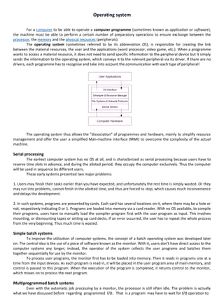
  • 1. Operating system For a computer to be able to operate a computer programme (sometimes known as application or software), the machine must be able to perform a certain number of preparatory operations to ensure exchange between the processor, the memory and the physical resources (peripherals). The operating system (sometimes referred to by its abbreviation OS), is responsible for creating the link between the material resources, the user and the applications (word processor, video game, etc.). When a programme wants to access a material resource, it does not need to send specific information to the peripheral device but it simply sends the information to the operating system, which conveys it to the relevant peripheral via its driver. If there are no drivers, each programme has to recognise and take into account the communication with each type of peripheral! The operating system thus allows the "dissociation" of programmes and hardware, mainly to simplify resource management and offer the user a simplified Man-machine interface (MMI) to overcome the complexity of the actual machine. Serial processing The earliest computer system has no OS at all, and is characterized as serial processing because users have to reserve time slots in advance, and during the alloted period, they occupy the computer exclusively. Thus the computer will be used in sequence by different users. These early systems presented two major problems: 1. Users may finish their tasks earlier than you have expected, and unfortunately the rest time is simply wasted. Or they may run into problems, cannot finish in the allotted time, and thus are forced to stop, which causes much inconvenience and delays the development. 2. In such systems, programs are presented by cards. Each card has several locations on it, where there may be a hole or not, respectively indicating 0 or 1. Programs are loaded into memory via a card reader. With no OS available, to compile their programs, users have to manually load the compiler program first with the user program as input. This involves mounting, or dismounting tapes or setting up card decks. If an error occurred, the user has to repeat the whole process from the very beginning. Thus much time is wasted. Simple batch systems To improve the utilization of computer systems, the concept of a batch operating system was developed later on. The central idea is the use of a piece of software known as the monitor. With it, users don’t have direct access to the computer systems any longer; instead, the operator of the system collects the user programs and batches them together sequentially for use by the monitor. To process user programs, the monitor first has to be loaded into memory. Then it reads in programs one at a time from the input devices. As each program is read in, it will be placed in the user program area of main memory, and control is passed to this program. When the execution of the program is completed, it returns control to the monitor, which moves on to process the next program. Multiprogrammed batch systems Even with the automatic job processing by a monitor, the processor is still often idle. The problem is actually what we have discussed before regarding programmed I/O. That is a program may have to wait for I/O operation to
  • 2. finish and thus leads to the processor’s idling. The solution is to run multiple programs concurrently during a certain period so that whenever the current program has to wait for I/O devices, control may be transferred to another program. If needed, a third program may be loaded, or even more. This scheme is called multiprogramming or multitasking. With multiprogramming, the utilization of processor is greatly improved, but it has its own problems. To run multiple programs concurrently, the memory should be organized properly so that each program has its own space and does not invade others’. What’s more, at some moment, there may be more than programs ready to run. Thus some form of scheduling is needed to obtain better performance. Time-sharing system With multiprogramming, the overall system is quite efficient. However a problem remains. That is those jobs that come late in the batch job list won’t get chance to run until the jobs before them have completed, thus their users have to wait a long time to obtain the results. Some programs may even need interaction with users, which requires the processor to switch to these programs frequently. To reach this new goal, a similar technique to multiprogramming can be used, called time sharing. In such a system, multiple users simultaneously access the system through terminals, with the operating system interleaving the execution of each user program in a short burst of computation. For example, suppose a computer system may have at most 10 users at the same time, and the human reaction time is 200 ms. Then we may assign 200/10 = 20ms CPU time to the user programs one by one in a cyclic manner, thus each user will be responded within the human reaction time so that the computer system seems to service the user program itself. The following table gives the difference between the batch multiprogramming and time sharing: System call A system call is a request made by any program to the operating system for performing tasks -- picked from a predefined set -- which the said program does not have required permissions to execute in its own flow of execution. System calls provide the interface between a process and the operating system. Most operations interacting with the system require permissions not available to a user level process, e.g. I/O performed with a device present on the system or any form of communication with other processes requires the use of system calls. The fact that improper use of the system call can easily cause a system crash necessitates some level of control. The design of the microprocessor architecture on practically all modern systems (except some embedded systems) offers a series of privilege levels -- the (low) privilege level in which normal applications execute limits the address space of the program so that it cannot access or modify other running applications nor the operating system itself. It also prevents the application from directly using devices (e.g. the frame buffer or network devices). But obviously many normal applications need these abilities; thus they can call the operating system. The operating system executes at the highest level of privilege and allows the applications to request services via system calls, which are often implemented through interrupts. If allowed, the system enters a higher privilege level, executes a specific set of instructions which the interrupting program has no direct control over, then returns control to the former flow of execution. This concept also serves as a way to implement security. With the development of separate operating modes with varying levels of privilege, a mechanism was needed for transferring control safely from lesser privileged modes to higher privileged modes. Less privileged code could not simply transfer control to more privileged code at any point and with any processor state. To allow it to do so would allow it to break security. For instance, the less privileged code could cause the higher privileged code to execute in the wrong order, or provide it with a bad stack.
  • 3. Interrupt Processing An interrupt is a dynamic event that needs prompt attention by the CPU. Usually an interrupt only needs a short period of CPU time to serve it. After that the original process can resume its execution. There are two types interrupting events: hardware interrupts that are those issued by I/O device controllers when they need CPU to process I/O data, and software interrupts, also called traps, that are raised when the current process executes a special trap instruction to indicate that something wrong has happened or the process needs special service from the operating system (like performing some I/O operation). Only a limited number of types of interrupts are defined. For each type of I/O devices, there is a special program called an interrupt handler to serve the interrupt requests from these devices. For all software traps, there is also a special trap handler defined. Each type of interrupt has an associated priority level. A running process would only be interrupted by an interrupt source or trap of higher priority. When the CPU is executing an interrupt handler, the interrupt handler may be further interrupted by an interrupt source of even higher priority. As we mentioned earlier, each type of interrupts will be processed by its own special interrupt handler. These interrupt handlers are an important component of an operating system. The starting address of each of these interrupt handlers are saved in a table called an Interrupt Vector. The Interrupt Vector is usually stored at the lower end of the main memory, starting from address 0. Suppose an I/O device has ID 3, then the starting address of its interrupt handler is in memory address 3. Upon entering the interrupt processing phase, the following events will happen: a. Reset (put 0 in) the Interrupt Enabled Bit to disable further nested interrupting b. The hardware will automatically push all the values of the program counter and general purpose- registers into a system stack c. Suppose the Address Lines of the system bus is now carrying k, where k is a small integer, the kth memory word’s value (the starting address of the interrupt handler for the current interrupt source) will be loaded into the CPU program counter, and the CPU starts to run the interrupt handler. The interrupt handler will do the following steps: a. If necessary, save more state information for the interrupted process. For example, maybe the carry bit of the ALU is needed by this handler thus needs to be saved. b. Set (put 1 in) the Interrupt Enabled Bit to enable further nested interrupting c. Do the necessary processing designed for this type of interrupt or trap. Typically, some data will be transferred between a CPU register and one of the registers of an I/O device controller. Since the interrupt is now enabled, it is possible that the execution of this interrupt handler be further interrupted by sources of even higher priority. d. Restore any information saved in step a. e. Upon quitting the interrupt handler, pop the values of the program counter and general-purpose registers of the interrupted process back into these registers. f. Now the CPU can resume the execution of the interrupted process. Memory Internal storage areas in the computer. The term memory identifies data storage that comes in the form of chips, and the word storage is used for memory that exists on tapes or disks. Moreover, the term memory is usually used as a shorthand for physical memory, which refers to the actual chips capable of holding data. Some computers also use virtual memory, which expands physical memory onto a hard disk. Every computer comes with a certain amount of physical memory, usually referred to as main memory or RAM. You can think of main memory as an array of boxes, each of which can hold a single byte of information. A computer that has 1 megabyte of memory, therefore, can hold about 1 million bytes (or characters) of information. There are several different types of memory:
  • 4. RAM (random-access memory): This is the same as main memory. When used by itself, the term RAM refers to read and write memory; that is, you can both write data into RAM and read data from RAM. This is in contrast to ROM, which permits you only to read data. Most RAM is volatile, which means that it requires a steady flow of electricity to maintain its contents. As soon as the power is turned off, whatever data was in RAM is lost. ROM (read-only memory): Computers almost always contain a small amount of read-only memory that holds instructions for starting up the computer. Unlike RAM, ROM cannot be written to. PROM (programmable read-only memory): A PROM is a memory chip on which you can store a program. But once the PROM has been used, you cannot wipe it clean and use it to store something else. Like ROMs, PROMs are non- volatile. EPROM (erasable programmable read-only memory): An EPROM is a special type of PROM that can be erased by exposing it to ultraviolet light. EEPROM (electrically erasable programmable read-only memory): An EEPROM is a special type of PROM that can be erased by exposing it to an electrical charge. Cache Memory Cache (pronounced cash) memory is extremely fast memory that is built into a computer’s central processing unit (CPU), or located next to it on a separate chip. The CPU uses cache memory to store instructions that are repeatedly required to run programs, improving overall system speed. The advantage of cache memory is that the CPU does not have to use the motherboard’s system bus for data transfer. Whenever data must be passed through the system bus, the data transfer speed slows to the motherboard’s capability. The CPU can process data much faster by avoiding the bottleneck created by the system bus. As it happens, once most programs are open and running, they use very few resources. When these resources are kept in cache, programs can operate more quickly and efficiently. All else being equal, cache is so effective in system performance that a computer running a fast CPU with little cache can have lower benchmarks than a system running a somewhat slower CPU with more cache. Cache built into the CPU itself is referred to as Level 1 (L1) cache. Cache that resides on a separate chip next to the CPU is called Level 2 (L2) cache. Some CPUs have both L1 and L2 cache built-in and designate the separate cache chip as Level 3 (L3) cache. Cache that is built into the CPU is faster than separate cache, running at the speed of the microprocessor itself. However, separate cache is still roughly twice as fast as Random Access Memory (RAM). Cache is more expensive than RAM, but it is well worth getting a CPU and motherboard with built-in cache in order to maximize system performance. Process A process is an instance of a program running in a computer. It is close in meaning to task , a term used in some operating systems. In Windows and some other operating systems, a process is started when a program is initiated (either by a user entering a shell command or by another program). Like a task, a process is a running program with which a particular set of data is associated so that the process can be kept track of. An application that is being shared by multiple users will generally have one process at some stage of execution for each user.
  • 5. A process can initiate a subprocess, which is a called a child process (and the initiating process is sometimes referred to as its parent ). A child process is a replica of the parent process and shares some of its resources, but cannot exist if the parent is terminated. Processes can exchange information or synchronize their operation through several methods of interprocess communication. Process Model The process model is typically used in structured analysis and design methods. Also called a data flow diagram (DFD), it shows the flow of information through a system. Each process transforms inputs into outputs. The model generally starts with a context diagram showing the system as a single process connected to external entities outside of the system boundary. This process explodes to a lower level DFD that divides the system into smaller parts and balances the flow of information between parent and child diagrams. Many diagram levels may be needed to express a complex system. Primitive processes, those that don't explode to a child diagram, are usually described in a connected textual specification. The Five state Model: Events such as suspending and resuming are controlled by the MLS (Medium Level Scheduler). A suspended process is dormant and this happens mostly when it is being swapped out of memory by the memory management system. This decision is handled by the scheduler. The process could be suspended while in RUNNING, READY or BLOCKED state. The result is that two new state are produced READY SUSPENDED and BLOCKED SUSPENDED. Figure below represents five state model. I/O COMPLRTION ENTRY READY BLOCKED I/O WAIT DISPATCH RUNNING RESUME SUSPEND TIMEOUT SUSPEND RESUME TERMINATION READY SUSPENDED SUSPEND BLOCKED SUSPENDED I/O COMPLETION Five state diagram The five state diagram is derived from three stage diagram by adding the SUSPEND condition. The SUSPEND condition can apply to any one of the states which are READY, RUNNING and BLOCKED. A suspension on any state will stop the activity within that state. If the READY and BLOCKED state are SUSPENDED then we obtain two more states called SUSPENDED READY and SUSPENDED BLOCKED. If a RUNNING state is SUSPENDED then the process is removed from the RUNNING state and placed in the SUSPENDED READY state. It is also worth noting that if the I/O wait for BLOCKED SUSPENDED state returns the ‘awaited’ I/O request during the BLOCKED SUSPENDED state, the process is moved to the READY SUSPENDED state.
  • 6. Five states: New, Ready, Running, Blocked, Exit • New : A process has been created but has not yet been admitted to the pool of executable processes. • Ready : Processes that are prepared to run if given an opportunity. That is, they are not waiting on anything except the CPU availability. • Running: The process that is currently being executed. (Assume single processor for simplicity.) • Blocked : A process that cannot execute until a specified event such as an IO completion occurs. • Exit: A process that has been released by OS either after normal termination or after abnormal termination (error). Classical Problems of Synchronization 1. Bounded-Buffer Problem 2. Readers and Writers Problem READERS/WRITERS PROBLEM In dealing with the design of synchronization and concurrency mechanisms, it is useful to be able to relate the problem at hand to known problems and to be able to test any solution in terms of its ability to solve these known problems. In the literature, several problems have assumed importance and appear frequently, both because they are examples of common design problems and because of their educational value. One such problem is the producer/consumer problem, which has already been explored. In this section, we look at another classic problem: the readers/writers problem. The conditions that must be satisfied are as follows: 1. Any number of readers may simultaneously read the file. 2. Only one writer at a time may write to the file. 3. If a writer is writing to the file, no reader may read it. Writers Have Priority In the previous solution, readers have priority. Once a single reader has begun to access the data area, it is possible for readers to retain control of the data area as long as there is at least one reader in the act of reading. Therefore, writers are subject to starvation. Figure shows a solution that guarantees that no new readers are allowed access to the data area once at least one writer has declared a desire to write. For writers, the following semaphores and variables are added to the ones already defined: A semaphore rsem that inhibits all readers while there is at least one writer desiring access to the data area A variable writecount that controls the setting of rsem A semaphore y that controls the updating of writecount THE PRODUCER/CONSUMER PROBLEM We now examine one of the most common problems faced in concurrent processing: the producer/consumer problem. The general statement is this: there are one or more producers generating some type of data (records, characters) and placing these in a buffer. There is a single consumer that is taking items out of the buffer one at a time. The system is to be constrained to prevent the overlap of buffer operations. That is, only one agent (producer or consumer) may access the buffer at any one time. The problem is to make sure that the producer won’t try to add data
  • 7. into the buffer if it’s full and that the consumer won’t try to remove data from an empty buffer. We will look at a number of solutions to this problem to illustrate both the power and the pitfalls of semaphores. Let us add a new and realistic restriction to the producer/consumer problem: namely, that the buffer is finite. The buffer is treated as a circular storage, and pointer values must be expressed modulo the size of the buffer. The following relationships hold: Deadlock Recall that one definition of an operating system is a resource allocator. There are many resources that can be allocated to only one process at a time, and we have seen several operating system features that allow this, such as mutexes, semaphores or file locks. Sometimes a process has to reserve more than one resource. For example, a process which copies files from one tape to another generally requires two tape drives. A process which deals with databases may need to lock multiple records in a database. In general, resources allocated to a process are not preemptable; this means that once a resource has been allocated to a process, there is no simple mechanism by which the system can take the resource back from the process unless the process voluntarily gives it up or the system administrator kills the process. This can lead to a situation called deadlock. A set of processes or threads is deadlocked when each process or thread is waiting for a resource to be freed which is controlled by another process. Here is an example of a situation where deadlock can occur. Traffic gridlock is an everyday example of a deadlock situation. In order for deadlock to occur, four conditions must be true. • Mutual exclusion - Each resource is either currently allocated to exactly one process or it is available. (Two processes cannot simultaneously control the same resource or be in their critical section). • Hold and Wait - processes currently holding resources can request new resources • No preemption - Once a process holds a resource, it cannot be taken away by another process or the kernel. • Circular wait - Each process is waiting to obtain a resource which is held by another process. • The deadlock situation in the above code can be modeled like this.
  • 8. Deadlock detection and recovery As we saw above, if there is only one instance of each resource, it is possible to detect deadlock by constructing a resource allocation/request graph and checking for cycles. Graph theorists have developed a number of algorithms to detect cycles in a graph. The book discusses one of these. It uses only one data structure L a list of nodes. A cycle detection algorithm For each node N in the graph 1. Initialize L to the empty list and designate all edges as unmarked 2. Add the current node to L and check to see if it appears twice. If it does, there is a cycle in the graph. 3. From the given node, check to see if there are any unmarked outgoing edges. If yes, go to the next step, if no, skip the next step 4. Pick an unmarked edge, mark it, then follow it to the new current node and go to step 3. 5. We have reached a dead end. Go back to the previous node and make that the current node. If the current node is the starting Node and there are no unmarked edges, there are no cycles in the graph. Otherwise, go to step 3. Let's work through an example with five processes and five resources. Here is the resource request/allocation graph. The algorithm needs to search each node; let's start at node P1. We add P1 to L and follow the only edge to R1, marking that edge. R1 is now the current node so we add that to L, checking to confirm that it is not already in L. We then follow the unmarked edge to P2, marking the edge, and making P2 the current node. We add P2 to L, checking to make sure that it is not already in L, and follow the edge to R2. This makes R2 the current node, so we add it to L, checking to make sure that it is not already there. We are now at a dead end so we back up, making P2 the current node
  • 9. again. There are no more unmarked edges from P2 so we back up yet again, making R1 the current node. There are no more unmarked edges from R1 so we back up yet again, making P1 the current node. Since there are no more unmarked edges from P1 and since this was our starting point, we are through with this node (and all of the nodes visited so far). We move to the next unvisited node P3, and initialize L to empty. We first follow the unmarked edge to R1, putting R1 on L. Continuing, we make P2 the current node and then R2. Since we are at a dead end, we repeatedly back up until P3 becomes the current node again. L now contains P3, R1, P2, and R2. P3 is the current node, and it has another unmarked edge to R3. We make R3 the current node, add it to L, follow its edge to P4. We repeat this process, visiting R4, then P5, then R5, then P3. When we visit P3 again we note that it is already on L, so we have detected a cycle, meaning that there is a deadlock situation. Once deadlock has been detected, it is not clear what the system should do to correct the situation. There are three strategies. Preemption - we can take an already allocated resource away from a process and give it to another process. This can present problems. Suppose the resource is a printer and a print job is half completed. It is often difficult to restart such a job without completely starting over. Rollback - In situations where deadlock is a real possibility, the system can periodically make a record of the state of each process and when deadlock occurs, roll everything back to the last checkpoint, and restart, but allocating resources differently so that deadlock does not occur. This means that all work done after the checkpoint is lost and will have to be redone. Kill one or more processes - this is the simplest and crudest, but it works. Deadlock avoidance The above solution allowed deadlock to happen, then detected that deadlock had occurred and tried to fix the problem after the fact. Another solution is to avoid deadlock by only granting resources if granting them cannot result in a deadlock situation later. However, this works only if the system knows what requests for resources a process will be making in the future, and this is an unrealistic assumption. The text describes the bankers algorithm but then points out that it is essentially impossible to implement because of this assumption. Deadlock Prevention The difference between deadlock avoidance and deadlock prevention is a little subtle. Deadlock avoidance refers to a strategy where whenever a resource is requested, it is only granted if it cannot result in deadlock. Deadlock prevention strategies involve changing the rules so that processes will not make requests that could result in deadlock. Here is a simple example of such a strategy. Suppose every possible resource is numbered (easy enough in theory, but often hard in practice), and processes must make their requests in order; that is, they cannot request a resource with a number lower than any of the resources that they have been granted so far. Deadlock cannot occur in this situation. As an example, consider the dining philosophers problem. Suppose each chopstick is numbered, and philosophers always have to pick up the lower numbered chopstick before the higher numbered chopstick. Philosopher five picks up chopstick 4, philosopher 4 picks up chopstick 3, philosopher 3 picks up chopstick 2, philosopher 2 picks up chopstick 1. Philosopher 1 is hungry, and without this assumption, would pick up chopstick 5, thus causing deadlock. However, if the lower number rule is in effect, he/she has to pick up chopstick 1 first, and it is already in use, so he/she is blocked. Philosopher 5 picks up chopstick 5, eats, and puts both down, allows philosopher 4 to eat. Eventually everyone gets to eat. An alternative strategy is to require all processes to request all of their resources at once, and either all are granted or none are granted. Like the above strategy, this is conceptually easy but often hard to implement in practice because it assumes that a process knows what resources it will need in advance.
  • 10. SCHEDULING ALGORITHMS Short-Term Scheduling Criteria The main objective of short-term scheduling is to allocate processor time in such a way as to optimize one or more aspects of system behavior. Generally, a set of criteria is established against which various scheduling policies may be evaluated. The commonly used criteria can be categorized along two dimensions. First, we can make a distinction between user-oriented and system-oriented criteria. User oriented criteria relate to the behavior of the system as perceived by the individual user or process. An example is response time in an interactive system. Response time is the elapsed time between the submission of a request until the response begins to appear as output. This quantity is visible to the user and is naturally of interest to the user. We would like a scheduling policy that provides “good” service to various users. In the case of response time, a threshold may be defined, say 2 seconds. Then a goal of the scheduling mechanism should be to maximize the number of users who experience an average response time of 2 seconds or less First-Come-First-Served The simplest scheduling policy is first-come-first served (FCFS), also known as first-in-first-out (FIFO) or a strict queuing scheme. As each process becomes ready, it joins the ready queue. When the currently running process ceases to execute, the process that has been in the ready queue the longest is selected for running. FCFS performs much better for long processes than short ones. Consider the following example, based on one in [FINK88]: Round Robin A straightforward way to reduce the penalty that short jobs suffer with FCFS is to use preemption based on a clock. The simplest such policy is round robin. A clock interrupt is generated at periodic intervals. When the interrupt occurs, the currently running process is placed in the ready queue, and the next ready job is selected on a FCFS basis. This technique is also known as time slicing, because each process is given a slice of time before being preempted. With round robin, the principal design issue is the length of the time quantum, or slice, to be used. If the quantum is very short, then short processes will move through the system relatively quickly. On the other hand, there is processing overhead involved in handling the clock interrupt and performing the scheduling and dispatching function. Thus, very short time quanta should be avoided. One useful guide is that the time quantum should be slightly greater than the time required for a typical interaction or process function. If it is less, then most
  • 11. processes will require at least two time quanta. Figure 9.6 illustrates the effect this has on response time. Note that in the limiting case of a time quantum that is longer than the longest-running process, round robin degenerates to FCFS. Shortest Process Next Another approach to reducing the bias in favor of long processes inherent in FCFS is the Shortest Process Next (SPN) policy. This is a non-preemptive policy in which the process with the shortest expected processing time is selected next. Thus a short process will jump to the head of the queue past longer jobs. Figure show the results for our example. Note that process E receives service much earlier than under FCFS. Overall performance is also significantly improved in terms of response time. However, the variability of response times is increased, especially for longer processes, and thus predictability is reduced. Shortest Remaining Time The shortest remaining time (SRT) policy is a preemptive version of SPN. In this case, the scheduler always chooses the process that has the shortest expected remaining processing time. When a new process joins the ready queue, it may in fact have a shorter remaining time than the currently running process. Accordingly, the scheduler may preempt the current process when a new process becomes ready. As with SPN, the scheduler must have an estimate of processing time to perform the selection function, and there is a risk of starvation of longer processes. SRT does not have the bias in favor of long processes found in FCFS. Unlike round robin, no additional interrupts are generated, reducing overhead. On the other hand, elapsed service times must be recorded, contributing to overhead. SRT should also give superior turnaround time performance to SPN, because a short job is given immediate preference to a running longer job. THE CRITICAL-SECTION PROBLEM n processes all competing to use some shared data Each process has a code segment, called critical section, in which the shared data is accessed. Problem – ensure that when one process is executing in its critical section, no other process is allowed to execute in its critical section. Structure of process Pi repeat entry section
  • 12. critical section exit section remainder section until false; Solution to Critical-Section Problem 1. Mutual Exclusion. If process Pi is executing in its critical section, then no other processes can be executing in their critical sections. 2. Progress. If no process is executing in its critical section and there exist some processes that wish to enter their critical section, then the selection of the processes that will enter the critical section next cannot be postponed indefinitely. 3. Bounded Waiting. A bound must exist on the number of times that other processes are allowed to enter their critical sections after a process has made a request to enter its critical section and before that request is granted. Assume that each process executes at a nonzero speed. No assumption concerning relative speed of the n processes. PAGING When a program is selected for execution, the system brings it into virtual storage, divides it into pages of four kilobytes, transfers the pages into central storage for execution. To the programmer, the entire program appears to occupy contiguous space in storage at all times. Actually, not all pages of a program are necessarily in central storage, and the pages that are in central storage do not necessarily occupy contiguous space. The pieces of a program executing in virtual storage must be moved between real and auxiliary storage. To allow this, z/OS® manages storage in units, or blocks, of four kilobytes. The following blocks are defined: • A block of central storage is a frame. • A block of virtual storage is a page. • A block of auxiliary storage is a slot. A page, a frame, and a slot are all the same size: Four kilobytes. An active virtual storage page resides in a central storage frame. A virtual storage page that becomes inactive resides in an auxiliary storage slot (in a paging data set). Figure 1 shows the relationship of pages, frames, and slots. In Figure , z/OS is performing paging for a program running in virtual storage. The lettered boxes represent parts of the program. In this simplified view, program parts A, E, F, and H are active and running in central storage frames, while parts B, C, D, and G are inactive and have been moved to auxiliary storage slots. All of the program parts, however, reside in virtual storage and have virtual storage addresses. . z/OS uses a series of tables to determine whether a page is in real or auxiliary storage, and where. To find a page of a program, z/OS checks the table for the virtual address of the page, rather than searching through all of physical storage for it. z/OS then transfers the page into central storage or out to auxiliary storage as needed. This movement of pages between auxiliary storage slots and central storage frames is called paging. Paging is key to understanding the use of virtual storage in z/OS.
  • 13. z/OS paging is transparent to the user. During job execution, only those pieces of the application that are required are brought in, or paged in, to central storage. The pages remain in central storage until no longer needed, or until another page is required by the same application or a higher-priority application and no empty central storage is available. To select pages for paging out to auxiliary storage, z/OS follows a "Least Used" algorithm. That is, z/OS assumes that a page that has not been used for some time will probably not be used in the near future. DEMAND PAGING In computer operating systems, demand paging is an application of virtual memory. In a system that uses demand paging, the operating system copies a disk page into physical memory only if an attempt is made to access it (i.e., if a page fault occurs). It follows that a process begins execution with none of its pages in physical memory, and many page faults will occur until most of a process's working set of pages is located in physical memory. This is an example of lazy loading techniques. Demand paging follows that pages should only be brought into memory if the executing process demands them. This is often referred to as lazy evaluation as only those pages demanded by the process are swapped from secondary storage to main memory. Contrast this to pure swapping, where all memory for a process is swapped from secondary storage to main memory during the process startup. When a process is to be swapped into main memory for processing, the pager guesses which pages will be used prior to the process being swapped out again. The pager will only load these pages into memory. This process avoids loading pages that are unlikely to be used and focuses on pages needed druing the current process exection period. Therefore, we not only avoid unnecessary page load during swpping put we also try to preempt which pages we will need and avoid loading pages during execution. Commonly, to achieve this process a page table implementation is used. Our page table maps logical memory to physical memory. The page table uses a bitwise operator to mark if a page is valid or invalid. A valid page is one that currently resides in main memory. An invalid page table is one that currently resides in secondary memory. When a process tries to access a page, the following steps are generally followed: • Attempt to access page. • If page is valid (in memory) then continue processing instruction as normal. • If page is invalid then a page-fault trap occurs. • Check if the memory reference is a valid reference to a location on secondary memory. If not, we terminate the process (illegal memory access). Otherwise, we have to page in the required page. • Schedule disk operation to read the desired page into main memory. • Restart the instruction that was interrupted by the operating system trap. Advantages Demand paging, as opposed to loading all pages immediately: • Only loads pages that are demanded by the executing process. • When a process is swapped out (context switch) of memory, only those pages loaded in main memory need to be swapped out from main memory to secondary storage. • As there is more space in main memory, more processes can be loaded reducing context switching time which utilizes large amounts of resources. • Less loading latency occurs at program startup, as less information is accessed from secondary storage and less information is brought into main memory. • Does not need extra hardware support than what paging needs, since protection fault can be used to get page fault.
  • 14. Disadvantages • Individual programs face extra latency when they access a page for the first time. So demand paging may have lower performance than anticipatory paging algorithms such as prepaging, a method of remembering which pages a process used when it last executed and preloading a few of them, is used to improve performance. • Programs running on low-cost, low-power embedded systems may not have a memory management unit that supports page replacement. • Memory management with page replacement algorithms becomes slightly more complex. • Possible security risks, including vulnerability to timing attacks; see Percival 2005 Cache Missing for Fun and Profit MEMORY FRAGMENTATION Memory fragmentation eventually occurs on all NetWare 4 servers. Depending on the way you manage a server and the NetWare Loadable Modules (NLMs) you run, memory fragmentation can occur daily or occasionally, over a period of years. The most common cause of memory fragmentation is loading and unloading a scheduled NLM, such as a backup NLM. However, other automated NLMs can also cause memory fragmentation. For example, Novell's FTP server can cause memory fragmentation because the FTP server automatically loads when a request is received and then unloads when the request times out. Memory fragmentation can also be caused by NLMs that are unloaded and then reloaded as part of another process. For example, a backup NLM could schedule the unloading of a database NLM during the backup process. The backup NLM would then reload the database NLM when this process was completed. Since a database NLM is designed to be loaded and left running, this NLM makes permanent memory pool allocations, which are not returned to system memory when the NLM is unloaded. When the database NLM is reloaded, it may not reuse its permanent memory pool allocation and may, therefore, leave gaps in memory. As a result, memory fragmentation may occur. Although memory fragmentation can cause several errors, it most often results in Short Term Memory Alloc messages at the server console. These messages indicate that small memory resources are not available to the requesting process. SOLUTIONS FOR MEMORY FRAGMENTATION To resolve memory fragmentation, you should first ensure that the following command is included in the STARTUP.NCF file before you load disk drivers or name space drivers: • SET RESERVED BUFFERS BELOW 16 MEG = 300 By setting this parameter to 300, you allocate the largest memory pool possible in low memory to be used for short- term memory allocations. As a result, NetWare 4 does not need to allocate high memory to NLMs that make short-term memory allocations. If changing this parameter does not resolve memory fragmentation, you must down the server and restart it. If the server frequently experiences severe memory fragmentation, you should identify which NLMs are being loaded and unloaded and determine how you can leave these NLMs loaded all the time. MEMORY SEGMENTATION Memory segmentation occurs when system memory is presented to NetWare 4 as two or more noncontiguous memory blocks. Although several factors can cause this condition, the result is always the same: The NetWare Cache Memory Allocator cannot use all of the installed RAM. Depending on the cause, NetWare 4 may or may not see all of the installed RAM.
  • 15. If the NetWare Cache Memory Allocator cannot use all of the installed RAM, the server may display error messages. Most frequently, the server reports that the NetWare Cache Memory Allocator is out of available memory. SOLUTIONS FOR MEMORY SEGMENTATION The solutions used to resolve memory segmentation on NetWare 3 servers do not work on NetWare 4 servers. NetWare 3 is based on a multipool memory model and doesn't allocate memory for the NetWare Cache Memory Allocator until the first volume is mounted. As a result, you can prevent disk drivers from loading in the STARTUP.NCF file, and you can use the REGISTER MEMORY command before loading disk drivers and mounting volumes in the AUTOEXEC.NCF file. NetWare 3 can then see all of the available memory before allocating memory for the NetWare Cache Memory Allocator. Unlike NetWare 3, NetWare 4, is based on a single-pool, flat-memory model. When NetWare 4 is initialized, it immediately allocates memory for the NetWare Cache Memory Allocator. As a result, NetWare 4 can allocate only the memory that is physically available at the time. Once NetWare 4 allocates memory for the NetWare Cache Memory Allocator, NetWare 4 cannot dynamically reallocate this memory. If you use the REGISTER MEMORY command to resolve memory segmentation, NetWare 4 cannot use the additional memory it sees for internal processes. NetWare 4 can use this additional memory only for file cache buffers. To resolve memory segmentation, you should first ensure that you have not imposed false memory limitations on the server. Loading a DOS memory manager (HIMEM.SYS or EMM386.EXE, for example) in the CONFIG.SYS file is one of the most common causes of memory segmentation. You should also ensure that you are not loading a CONFIG.SYS file on the server's boot disk or boot partition. CONCLUSION Memory fragmentation occurs with all operating systems, not just NetWare 4. If memory fragmentation begins to affect system performance or data integrity, you must reboot the server. Memory segmentation, on the other hand, is caused by the physical limitations of the computer. (Such physical limitations also affect all operating systems, not just NetWare 4.) Either the computer is limited through its inherent design or through the use of devices that prevent NetWare 4 from directly addressing all of the available memory. The best solution is to use a computer that does not have these physical limitations. PAGE REPLACEMENT ALGORITHMS Regardless of the resident set management strategy (discussed in the next subsection), there are certain basic algorithms that are used for the selection of a page to replace. Replacement algorithms that have been discussed in the literature include • Optimal • Least recently used (LRU) • First-in-first-out (FIFO) • Clock The optimal policy selects for replacement that page for which the time to the next reference is the longest. It can be shown that this policy results in the fewest number of page faults [BELA66]. Clearly, this policy is impossible to implement, because it would require the operating system to have perfect knowledge of future events. However, it does serve as a standard against which to judge real world algorithms. Figure gives an example of the optimal policy. The example assumes a fixed frame allocation (fixed resident set size) for this process of three frames. The execution of the process requires reference to five distinct pages. The page address stream formed by executing the program is 232152453252 which means that the first page referenced is 2, the second page referenced is 3, and so on. The optimal policy produces three page faults after the frame allocation has been filled.
  • 16. The least recently used (LRU) policy replaces the page in memory that has not been referenced for the longest time. By the principle of locality, this should be the page least likely to be referenced in the near future. And, in fact, the LRU policy does nearly as well as the optimal policy. The problem with this approach is the difficulty in implementation. One approach would be to tag each page with the time of its last reference; this would have to be done at each memory reference, both instruction and data. Even if the hardware would support such a scheme, the overhead would be tremendous. Alternatively, one could maintain a stack of page references, again an expensive prospect. The first-in-first-out (FIFO) policy treats the page frames allocated to a process as a circular buffer, and pages are removed in round-robin style. All that is required is a pointer that circles through the page frames of the process. This is therefore one of the simplest page replacement policies to implement. The logic behind this choice, other than its simplicity, is that one is replacing the page that has been in memory the longest: A page fetched into memory a long time ago may have now fallen out of use. This reasoning will often be wrong, because there will often be regions of program or data that are heavily used throughout the life of a program. Those pages will be repeatedly paged in and out by the FIFO algorithm. Continuing our example in Figure 8.15, the FIFO policy results in six page faults. Note that LRU recognizes that pages 2 and 5 are referenced more frequently than other pages, whereas FIFO does not. Many of these algorithms are variants of a scheme referred to as the clock policy. The simplest form of clock policy requires the association of an additional bit with each frame, referred to as the use bit. When a page is first loaded into a frame in memory, the use bit for that frame is set to 1.Whenever the page is subsequently referenced (after the reference that generated the page fault), its use bit is set to 1. For the page replacement algorithm, the set of frames that are candidates for replacement (this process: local scope; all of main memory: global scope5) is considered to be a circular buffer, with which a pointer is associated. When a page is replaced, the pointer is set to indicate the next frame in the buffer after the one just updated. When it comes time to replace a page, the operating system scans the buffer to find a frame with a use bit set to zero. Each time it encounters a frame with a use bit of 1, it resets that bit to zero and continues on. If any of the frames in the buffer have a use bit of zero at the beginning of this process, the first such frame encountered is chosen for replacement. If all of the frames have a use bit of 1, then the pointer will make one complete cycle through the buffer, setting all the use bits to zero, and stop at its original position, replacing the page in that frame. We can see that this policy is similar to FIFO, except that, in the clock policy, any frame with a use bit of 1 is passed over by the algorithm. The policy is
  • 17. referred to as a clock policy because we can visualize the page frames as laid out in a circle. A number of operating systems have employed some variation of this simple clock policy (for example, Mastics [CORB68]).
  • 18. INDEX • Operating system and its Types Serial processing Simple batch systems Multiprogrammed batch systems Time-sharing system • System call • Interrupt Processing • Memory • Cache Memory • Process and Process Model • Classical Problems of Synchronization • Deadlock Deadlock detection and recovery • Scheduling Algorithms • THE CRITICAL-SECTION PROBLEM • PAGING • MEMORY FRAGMENTATION • MEMORY SEGMENTATION • PAGE REPLACEMENT ALGORITHMS