
Recomendados
Recomendados
Más contenido relacionado
La actualidad más candente
La actualidad más candente (20)
Destacado
Destacado (20)
Similar a Simple Wireless Radio Data Link
Similar a Simple Wireless Radio Data Link (20)
Último
Último (20)
Simple Wireless Radio Data Link
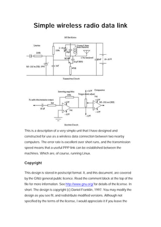
- 1. Simple wireless radio data link This is a description of a very simple unit that I have designed and constructed for use as a wireless data connection between two nearby computers. The error rate is excellent over short runs, and the transmission speed means that a useful PPP link can be established between the machines. Which are, of course, running Linux. Copyright This design is stored in postscript format. It, and this document, are covered by the GNU general public licence. Read the comment block at the top of the file for more information. See http://www.gnu.org/ for details of the license. In short: The design is copyright (c) Daniel Franklin, 1997. You may modify the design as you see fit, and redistribute modified versions. Although not specified by the terms of the license, I would appreciate it if you leave the
- 2. original credits intact (feel free to add yout own). The above JPG, a derivative work of the postscript file, also has the copyright attachment. FYI, here is the full GNU general public licence. Please take the time to read it. For the best quality schematic, here is a postscript version of the above image, and here is the original xfig file. Legal issues The legality of operating FM transmitters in the broadcast band depends on where you live. In Australia, only low power devices (like this one) are allowed without a commercial license. It should be noted that the limit is 30 uW without a commercial license, for operations in the FM broadcast band. This transmitter is hopefully operating well below that (20 uW or thereabouts). In any case make sure you are not interfering with any commercial radio transmission. You may wish to 'detune' the tx/rx to operate at frequencies below 88 MHz if you find you are being swamped by commercial transmitters, or are causing interference. Specifications Max bit rate: Tested reliably to 19200 baud. I found that the cutoff was very steep on one radio- it worked fine at 19200 but any higher and it was completely useless (e.g. 21600). The limiting factor is the quality of the receivers that are used. If you can tolerate a higher error rate, by all means try a higher speed but remember that if the receiver is using a TDA7000 then it will be band-limited to 10kHz anyway so the best you will get is 9600 (maybe not even that). Remember that a single bit error means that if you are running PPP, the entire packet will need to be re-transmitted - so even low error rates can reduce your throughput dramatically unless the errors occur in tight clusters (in my experience this is the most common distribution). This is entirely dependant upon the radio you choose - more on this later. Input / output "standard": RS-232, though I see no reason why other low bit- rate protocols would work. Perhaps even with such features as addressing! RS-485 anyone?
- 3. Range: Unknown. Tested on a 20 metre link. The transmitter design is reckoned to have a range of several hundred metres... but the signal strength and signal - noise ratio may deteriorate over this range. Try it! Error rate: ? depends on many factors: distance, proximity to other radio stations etc. Over 20 metres, the error rate was virtually zero. If the receiver is not quite on-station, expect to see total garbage. It MUST be tuned spot on the correct frequency. Required channel separation: depends (obviously) on the selectivity of the receiver. A cheap FM radio should allow several MHz. The transmitter can go up to 110 MHz or so, and possibly higher if 2N2222 transistors are used instead of the 547s. I don't know of any lower limits, but I would not like to go below 80 MHz - the radio may not like being detuned that much, particularly if it uses a chip with a built - in band pass filter! Suggested Uses • moving data without floppies (were speed is irrelevant); • turn a 286, XT, Z80 or an apple 2 into a VT100 terminal; • link two physically separated computers or networks via PPP; • broadcast data from a single source to multiple receivers; • short range telemetry / mobile computers / robots; and • network games! Cost Tx: ~$A10.00, although if you use junk like I did this is actually zero :-) Rx: Requires an FM radio + ~A$5.00 worth of parts. For PPP etc you want two Tx/Rx pairs, each pair tuned together. I used a 741 op-amp, and BC547 transistors. The cheapest of everything will work perfectly well. The cost estimate assumes that one buys new 25 pin connectors from DSE... as I have discovered not always the best value for money. Equipment
- 4. To make the transmitter, all you need is a soldering iron, some solder, a small prototype board (the smallest that will fit all the components). The receiver is more fiddly - you will DEFINITELY need a CRO to correctly identify the output of the discriminator, unless you have a circuit diagram of the receiver. Also, you will need two female RS-232 connectors, either 9 or 25 pin depending on what kind of connector the port uses. 3 core shielded cable is a good idea for the run from computer to tx/rx. Instructions for construction / testing Tx: Build the transmitter. Ensure that the transmitter is as tightly constructed as possible, with very short wires and no dodgy joints. A PCB could be a good idea (TE sells one that would nearly suit, i.e. the Voyager) but I have had good results with point-to-point wiring on a wire-wrap board (NOT using wire- wrap as this introduces excess stray inductance) Make sure that there is adequate capacitance across the supply rails, particularly if the transmitter shares a power supply with a receiver. Consider some kind of shielding - a sheet of aluminium foil with contact on both sides can be used to make a decent shield. Connect the finished article to a spare serial port. Assuming you are running Linux (of course you are), do something like "yes 'Hello World' > /dev/cua1", after setting the serial port to the desired baud rate. For anyone unfortunate enough to be using a Microsoft OS, perhaps you could use Telix or some such comms program to send stuff to the port. Perhaps you should also think about changing OSs :) Listen on an FM radio, around 88 - 90MHz for a clear (!) peridic gggnnnnhhhngggnnnnggghhhnnggg sort of sound. At higher baud rates it sounds more like whhwhnnnwhwhwwnwnwwhnwnnn. A CRO is good! Very good! A better way to test the transmission capability is something like the following script: #!/bin./sh while [ 1 ] ; do echo ABCDEFGHIJKLMNOPQRSTUVWXYZabcdefghijklmnopqrstuvwxyz1234567890 > /dev/cua1 sleep 1 done
- 5. which will give you some silence as well, plus it tests some more bits. If you are really adventurous, download the ANSI colour text logo generator (I have mine set up to create a new /etc/issue every boot with updated system info) and repeatedly cat it to the serial port. This uses the MSB of the word, which allows you to effectively test the correct detection of all the bits. There should not be much variation in the timing of the bits, but if you use an adjustable comparator you may find that you need to 'tune' this as well as tuning the radio. There should be dead silence when not transmitting. If not, retune the transmitter to another less noisy location (stretch or squeeze the coils, or turn the trimmer capacitor for finer control) and find the spot again. Rx: The hard part. Power up the receiver (NOT from the mains) and, with the Tx running, tune to the right frequency. Observe the signal at the speaker using a CRO - the rectangular wave has been severely distorted by the capacitive coupling of the audio output stages of the radio. Thus, you need to bypass this stage and connect the output of the detector to your own audio output stage. Probe various points around the chip with the CRO AC coupled, until you find a signal which looks more square than the output signal (should in fact be almost perfectly square). This should be the output of the FM discriminator, which would probably either be a Foster-Seely detector or a ratio detector. The AC coupling on the CRO is required because the amplitude of this square wave is small, and there may be a large DC offset. The multiple capacitive coupling in the audio stage will be more severe than that of the capacitor in the CRO. Now, with the best signal point established, you should connect this via a relatively large capacitor to the input of an inverting op-amp with a gain of 100 or therabouts (which should ensure clipping = nice clean rectangular wave). The polarity of the capacitor, assuming it to be electrolytic or tantalum, depends on the polarity of the DC offset of the discriminator output. If it is positive, connect the + lead of the capacitor to this point, and vise versa. For some radios (the DSE one in particular) you may need a comparator on the end of the inverting amplifier to clean up the square wave. The reason is that as the gain increases, the slew rate deteriorates - thus, unless you have a very strong signal (not really the
- 6. case with the DSE) you will need to reduce the gain (reduce the 100K resistor or increase the 1K resistor) and add an adjustable comparator as shown in the circuit diagram. Please do not write to me to tell me that there are better designs. I know that it could be done better, but this design works, and works well. Issues of stability and voltage drift due to changes in supply voltage are valid concerns, but these are left as an exercise to the reader. Alternatively you can build your own using a TDA7000 chip or similar. You should use the manufacture's (Phillips) design for the printed circuit board as the layout is quite critical. Phillips is too cheap and nasty to give away free samples, and the chips are not cheap - so if you can, I suggest you avoid this option. I investigated buying some chips from Farnell - it would have worked out at $A13 (including tax and postage) each which is more than some cheap radios I have seen, such as the DSE one - and this is before any PCBs or other components are paid for. That said , the TDA7000 is a fine chip, but it is band-limited to 10 kHz which rather limits its usefulness for data work. A cheap radio with discrete components or better ICs should work just fine at up to 19200 baud. The DSE radio has two chips, and the discriminator output is one of the pins of one of these ICs (see later). As to your choice of radio, it should be mono, and preferably as cheap and nasty as possible. I say this because the whole point of the design is to produce a cheap, reasonably quick and reasonably reliable data link. You could use a fancier radio, but it would be overkill. Stereo is definitely a waste of money. I have two radios, one is a Dick Smith Electronics cheapo AM/FM job. It costs $A11.50 - the bottom of their range, and works fine at 19200. On the other hand, I have an old clock radio which also works fine, but is more fiddly to tune - too selective. The DSE radio is pretty sloppy w.r.t. tuning, and is a good receiver for this purpose. It is also very compact, and conveniently will run happily off a 5V DC supply. LO-FI is very much the name of the game, though the frequency response of the chip should be good enough for data. Should you choose the DSE radio, here are some important things to note: • 1. You DEFINITELY need the comparator stage of the receiver circuit as shown in the above diagram.
- 7. • 2. To save you the trouble, the discriminator output is pin 3 of the IC in the 'middle' of the C shaped board - the chip is a Toshiba TA2003P. • 3. The radio is cat number A-4350 The FM scheme used here switches the output frequency between two values. Thus, one can tune the receiver to either of them, and see a square wave output (one being the complement of the other - more or less). You should choose an inverting or non-inverting amplifier for this stage - I use an inverting one and tune to the lower frequency. The receiver is almost being used as an AM radio - but at the right frequency and with the high selectivity of the existing superhetrodyne system intact. To get the best reception, connect the output of the op-amp (which should be powered on +/- 10 to 12 volts for RS-232 compatiblity) to the RD line of the target computer. Then cat the serial port (cat /dev/ttyS1) and you should see "Hello world" or whatever you are transmitting repeated over and over. If you get something which is consistantly wrong, i.e. a repeated sequence which contains no random component, but which is obviously data of some sort, try tuning the radio up or down while observing the output on the screen. Also try adjusting the output volume of the radio (the speaker could be replaced by a resistor if you don't like the sound) to adjust the loading of the detector output by the audio stage (this made a big difference for my test setup). When this is working nicely, repeat the process with another Tx, Rx pair but at a somewhat different frequency. Make sure that the transmissions at one frequency are not picked up by the adjacent receiver at another. If there is some crosstalk, increase the channel separation. You could also try vertically polarizing one antenna and horizontally polarizing the other to reduce crosstalk. When you have it working properly in both directions at the same speed, try setting up PPP! Then telnet, ftp, netscape, NFS etc can all be used. Remeber that NO hardware control signals are avaliable so you must use software control - which reduces the throughput slightly. Just pretend it's a null modem with only RD, TD and GND connected.
- 8. For best results, use shielded cable to the computer - and use enough cable so that the tx/rx are not too close to the machine. Also, if possible, keep the tx/rx physically separated as this reduces the likelyhood of crosstalk. More information "14 FM Bugs to build" and "5 More FM Bugs to build" by Colin Mitchell of Talking Electronics are good sources of information on FM transmitter design These books are the inspiration for this design - I would never have believed the quality that could be attained using cheap hardware had I not read these publications. It and other interesting books on electronics can be had by writing to: Talking Electronics 35 Rosewarne Ave Cheltnam Victoria 3192 AUSTRALIA You may be able to modify some of his designs for better performance than with this simple transmitter, however once again note that you should remove the audio stage and use a limiter such as the one used here. Note that I do not endorse any of the right-wing rhetoric he espouses between good electronic designs in this book! He is a bit of a nut... he talks a lot about the 'waste of bandwidth by community groups and ethnic minorities'. They sell good books, plus kits etc. However, the electronics is first rate and the designs all work (unlike DSE in my experience). This is NOT one of their designs so please don't ask them for a kit! (I have no association with them by the way). The transmitter used here is inspired by the 'Voyager' design, minus the audio stage and with some other bits added. I got some info on data transmission theory from "Introduction to Communications Systems" by F. Stremler. A good if expensive book. You don't really need that if you are not interested in the theory of communications and signals. Did you get it working? I would love to hear from successful constructors, and even unsuccessful ones. If you have problems with this circuit, try to describe them and I will do my best to help you out. Like I said, this design works for me, and there is no reason for it not to work for you.
- 9. © 1995-2003 Daniel Franklin Telecommunications and Information Technology Research Institute University of Wollongong, Northfields Ave, NSW 2522, AUSTRALIA Phone: +61 2 4221 4442 Fax: +61 2 4221 3236 Email:d.franklin@ieee.org