Fieldbus wiring guide
•Descargar como PPTX, PDF•
14 recomendaciones•5,792 vistas

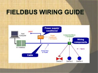
1. Fieldbus networks replace traditional 4-20 mA analog signals with digital communication over twisted-pair wiring. 2. The key changes are replacing the analog control system and field devices with digital ones that communicate over FOUNDATION fieldbus, and adding terminators to the wire pairs. 3. Devices can be connected in a bus, tree, daisy chain, or point-to-point topology with optional repeaters, bridges or gateways to extend the network or connect different segments.

Recomendados
Más contenido relacionado
La actualidad más candente
La actualidad más candente (20)
Destacado
Destacado (13)
Similar a Fieldbus wiring guide
Similar a Fieldbus wiring guide (20)
Último
Último (20)
Fieldbus wiring guide
- 3. The only changes are: 1. The control system‟s 4-20 mA interface is replaced with one that “talks” FOUNDATION fieldbus. We called it a FOUNDATION Fieldbus Interface (FFI). This FFI could, in fact, be in a personal computer or a PLC. 2. The analog field device is replaced with one that talks FOUNDATION fieldbus. 3. A terminator is added at the FFI end of the wire pair. Another terminator is added at the field device end of the wire pair. The FFI may have a built-in terminator so that you don‟t have to add one.
- 9. Fieldbus Network With Additional Devices Added Fieldbus Network With Chained Devices
- 10. Repeaters are active bus powered, or non-bus powered devices, used to extend a fieldbus network. A maximum of four (4) repeaters and/or active couplers can be used between any two devices on a fieldbus network Using four repeaters, the maximum distance between any two devices on that network is 9500 m. A Bridge is an active bus powered, or non-bus powered device, used to connect fieldbus segments of different speeds (and/or physical layers - e.g. wire, optical fiber,..) together to form a larger network. A Gateway is an active bus powered, or non-bus powered device, used to connect a fieldbus segment or segments to other types of communications protocols (e.g. Ethernet, RS232, ..).
- 11. Addition of a Device and a Bridge to Fieldbus Network
- 15. Polarity The Manchester signal used by fieldbus is an alternating voltage that changes polarity once or twice per bit. In unpowered networks only this alternating voltage exists. In powered networks the alternating voltage is superimposed onto the DC voltage being used to power the devices. In either case, the fieldbus receive circuits look at only the alternating voltage. Positive voltage swings have one meaning, negative swings have the opposite meaning. Therefore, the fieldbus signal is polarized. Field devices must be connected so that they all see the signal in correct polarity. If a field device is connected “backwards” it will see an inverted version of the alternating voltage and won‟t be able to communicate.
- 16. Short Circuit Protection Short circuit protection has logic that detects a short, removes the shorted circuit from the segment, and lights a LED. This prevents a short from affecting the segment.
- 18. DC Power for Two-Wire Field Devices
- 19. If you have 2-wire field devices in your network, you have to make sure they have enough voltage to operate. Each device should have at least 9 volts. You need to know: 1. The current consumption of each device. 2. Its location on the network. 3. The location of the power supply on the network. 4. The resistance of each cable section. 5. The power supply voltage.
- 21. Installation
- 23. Bus Topology
- 24. Tree Topology
- 27. Terminators A terminator is an impedance matching module used at or near each end of a transmission line. There need to be two (and ONLY TWO) terminators per bus segment. The terminators prevent distortion and signal loss, and are typically purchased and installed as a preassembled, sealed module. The user/installer need not be concerned about or assemble individual electrical resistors and capacitors.
- 28. Terminal Blocks Terminal blocks can be the same terminal blocks as used for 4-20 mA. The terminal blocks typically provide multiple bus connections, such that a device can be wired to any set of bus terminals.
- 31. Power Supply • Wide input range: 90-264 VAC (47-440 Hz) 127-367 VDC • 24 VDC, 1.5 A output. • Galvanically isolated • Failure indication and output
- 32. Power Conditioner •A fieldbus power conditioner prevents the high frequency communications signal from being shorted out by the DC voltage regulators. •Typical power conditioners make 350 to 500mA available on the bus.
- 33. Grounding
- 35. Alternative earthing arrangement for improved EMC performance
- 36. Multiple grounding with potential equalization
- 37. Wiring DOs and Don’ts Normal wiring procedures apply: • No loose connections • No exposed conductors • Water proof junction boxes • Signal wires not too close to power wires • No safety barriers in parallel
- 39. Basic Troubleshooting • Correct polarity • Correct tag and address • Integrity of the fieldbus network • Supply voltage is sufficient, min 9.5 V even during communication. •Wiring errors, including wrong connections, open or short circuits, intermittent •Connections and reversed polarity • Too many or too few terminators on each segment • Faulty „out of the box‟ physical layer components or fieldbus instruments • Inadequate grounding, such as multiple grounds in field, or the absence of any clear grounding strategy
- 40. Communication Errors • Poor connections • Wrong or no terminator placement • Too low or unstable power supply • Too long or over-populated spurs • Wrong or no grounding • Water filling due to poor plugs and cable-glands
- 41. Troubleshooting
- 42. Periodic monitoring • Short-circuits between the fieldbus + or – and the cable shield. • The signal level of each participant on the bus. A minimum level is specified by Foundation fieldbus specifications. Low or high levels on all devices suggest incorrect bus termination, but if the faulty signal level is only on one device, there is possibly a problem on a single spur. • DC voltage on the bus, indicating correct functioning of power supply/conditioner. • Noise: A maximum level is specified by Fieldbus specification. • Retransmissions. This provides a good measurement of physical layer health; retries can obscure faulty device or network.
- 43. Tools
- 46. Signals
- 61. Bad Installation
- 62. Bad Installation
- 63. Bad Installation
- 64. Configuration
- 66. Local Adjustment
- 67. Redundancy •No provision is made within either fieldbus standard for redundant segment communications. •Various fieldbus vendors, including major process control companies, have developed redundant fieldbus schemes that involve complete duplication of all equipment.
- 72. Fault-Tolerance with Redundant H1 Cards
- 73. Cabling