SlideShare una empresa de Scribd logo
1 de 7
Descargar para leer sin conexión
International Journal of Engineering Research and Development
e-ISSN: 2278-067X, p-ISSN: 2278-800X, www.ijerd.com
Volume 6, Issue 2 (March 2013), PP. 81-87

               Analysis of Friction Clutch plate using FEA
                            P.Naga Karna1, Tippa Bhimasankara Rao2
         1
         PG Student, Department of Mechanical Engineering, Nimra Institute of Science and Technology
 2
     HOD, Department of Mechanical Engineering, Nimra Institute of Science and Technology, Vijayawada, AP,
                                                  INDIA


        Abstract:- The object of the present work is to observe the stress distribution and the temperature
        distribution of the clutch plate by changing the material. And for that we are taken one existing
        clutch plate dimensions and modeled it by using Pro-e after analysis is done by using Ansys. Here
        we have done two types of analyses on clutch plate namely static analysis and thermal analysis. By
        performing these analyses we got the results namely stress distribution and temperature distribution.
        Finally we compare the results steel and aluminium wet clutch plates.

        Keywords:- Analysis, modeling, static analysis, thermal analysis.

                                           I.       INTRODUCTION
         A clutch is that part of engine which engages or disengages power from the engine crankshaft to
transmission. A clutch is mechanism by which you change the gears. In simple words, it turns on or off power to
rear wheel. A clutch is made of clutch assembly which includes clutch plate, Clutch basket, Clutch hub, pressure
plates, Clutch springs, lever and clutch cable. A clutch in which there is provided a clutch disc having clutch
facings made of cerametallic or like material, a flywheel having a friction surface to be brought into frictional
contact with one of the facings, and a pressure plate supported by a clutch cover for conjoint rotation with the
flywheel and urged in a direction to press the facing against the flywheel, with the pressure plate having a
friction surface to be brought into frictional contact with the other facing. Segments made of heat-treated hard
steel plate are fixed to each of the flywheel and the pressure plate to provide the friction surface thereof.
Clutch Engaged/Disengaged – On most motorcycles, the clutch is operated by the clutch lever, located on the
left handlebar. No pressure on the lever means that the clutch plates are engaged (driving), while pulling the
lever back towards the rider will disengage the clutch plates, allowing the rider to shift gears. There are several
types of clutch plates available which are divided into external and internal tooth and the most commonly used
materials for the clutch plates are steel and for friction material cerametallic or like material which is named as
Kevlar and it is a composite material.

                                           II.      CLUTCH PLATE
           A clutch plate is part of series of discs inside of a transmission. The clutch plate is round and has a
friction sensitive surface that allows it to grip. It sits next to the fly wheel, which is connected to the drive shaft
permanently. That means the flywheel immediately starts to spin as soon as the engine is turned on and the
motor turns the crankshaft. When this happens in a manual transmission, the clutch must be disengaged. That is,
it is pulled back from the flywheel, so it can spin without engaging the wheels.


                                                 Fig.1 Clutch Plates

                                                          81
Analysis of Friction Clutch plate using FEA

                                  III.     TYPES OF CLUTCH PLATES
        Wet Clutch
         Wet clutch are universal and found on any bike. Almost 99% of motorcycle manufactured uses this
kind of clutch. In the wet clutch set up the entire clutch is inside the case of the bike. Here it is bathed in oil
which acts like a kind of dampener. It stops the clutch from knocking on itself.

        Dry Clutch
         The dry clutch is almost identical to the wet clutch the only difference s there are seals on the shafts
that keep oil out. In the dry clutch set up the entire clutch is outside the case of the bike. There is no oil
circulated in to the clutch, which result into clutch knocking on itself. Ducati‟s are almost the

                   IV.      CLUTCH PLATE MANUFACTURING PROCEDURE
         First type
          Concurrently as seen in FIG.2 the remaining line of cut segments 14b-z advances the second segment
14b to the transfer position 71 in the shuttle assembly 70.the shuttle assembly 70 engages the second keystone
segment 14b and moves in a reverse direction and transfer the second segment 14b in to a first empty pocket 97
of the adjacent second indexing fixture 92. The second indexing fixture 92 is located opposite, or at a180
degrees, from the first indexing fixture 91.Continuing with the assembly steps, the first indexing fixture 91
rotates to its next, or second, there by exposing another, or second, empty pocket, for case of illustration, each
pocket will generally be referred to as 96 or 97. But it should be understood that the no. of pockets. In each
indexing fixture is depended up on the no. of key stone. Friction segments that are desired on the friction plate.
The shuttle assembly 70 again reverse direction, engages a third key stone segment 14c, now beginning moved
in to the transfer position 71, and transfer the third segment 14c in to the second pocket 96 in the first indexing
fixture 91. Concurrently, the second indexing fixture 92 rotates one position there by exposing another, or
second empty pocket for receiving the fourth cut segment 14d. The sequence of alternating placements of key
stone statement segments continues until all the pockets 96 and 97 in both the first 91 and second 91 indexing
fixtures have been filled with key stone segment 14.


                            Fig.2:-First type of Clutch plate manufacturing procedure

         Second type
          Referring now to Fig.3, a plan view of the indexing fixture 91 is shown; the direction of travel is
indicated by arrow z of alternating segments 14a, 14c, 14e and 14g travelling along the bottom track 74.The
indexing fixture 91 comprises an indexing plate 94 having a plurality of integrally machined segment pockets 96.
In the embodiment shown, there are 20 segments pockets in the indexing plate 94. However, it should be
understood that the indexing plate 94 can have different no. of pockets, depending on the no. of individual
segments to be positioned on a core plate. It should be further understood that the second indexing figure 92 can
be substantially identical to the first indexing figure 91 will be described in detail herein. it should be further
understood however, that such description also adequately describes the second indexing figure 92.
          The pockets 96 are slightly recessed in the indexing plate 94 to allow for accurate, vertical, radial and
circumferential location of each segment 14. In certain embodiments, the depth of the pockets 96 ranges from
about 0.020 to about 0.030 inches. Further, the key stone or trapezoidal, shape of the segment facilities accurate
positioning of each segment 14 in the corresponding pocket 96.Each pocket 96 defines a separate vacuum port
98. typically, the cut segments have an adhesive or glued bracking such that the porosity of the cut segment is
relatively low,therefore,the vacuum port 98 is used to apply a vacuum to further maintain the positioning of the
segment 14 in the pocket 96(if required).in the embodiment shown, the indexing plate 94 is operatively
connected to a rotating mechanism generally indicated as 100 which rotates, or indexes, the indexing plate 94.in
the case of a 20-cut segment core plate, for instance, the indexing figure 91 is moved or indexed 18 degrees

                                                        82
Analysis of Friction Clutch plate using FEA

between the placement of segments since indexing accuracy is important, the rotating apparatus 100 generally
comprises a servo motor and gear head assembly (not shown) which is Operatively mounted to the indexing
fixture 91.Once the pockets 96 have been filled with segments 14a-t, the segments are transferred to abounding
nest 140 in a suitable manner.


                                Fig3:- Second type of Clutch plate manufacturing

                                V.         ARRANGEMENT OF CLUTCH PLATES
          FIG: 4 is vertical cross sectional view of a whole of a multiple disc friction clutch. In FIG: 1 , the
multiple disc friction clutch is arranged between a crank shaft 1 and an input shaft 2 of a gear transmission 3 in a
power transmission path from an engine (not shown) of a motor cycle to a rear wheel (not shown), and is
provided with a clutch outer member 4 for take in power into the clutch, a clutch hub 5 for takeout power from
the clutch, a clutch output shaft 8 integrally formed with the input shaft 2, a clutch output tube shaft (rotating
member) 9 spline fitted to an outer peripheral surface of the clutch output shaft 8 in such a manner as to be
immovable in an axial direction of the clutch output shaft 8, a plurality of input friction plates 10 and output
friction plates 11 arranged between the clutch outer member 4 and the clutch hub 5, a pressing member (a
pressure plate or a pusher plate) 12 pressing both the friction plates 10 & 11 in an axial direction of the clutch
output shaft 8 (in other words an axial direction of the tube shaft 9), and coil shaped clutch spring 15 applying a
pressing load to the pressing member 12. Further, in addition to each of the member for pressing or the like,
there is provided a movable coupling hub 16 which is utilized for both of a pressing load increasing mechanism
and a back torque limiter mechanism mentioned below, as well as transmitting a torque between the clutch hub
5 and the tube shaft 9. A shift output shaft (not shown) of the gear transmission 3 is coupled to the rear wheel in
an interlocking manner, for example via a chain transmission mechanism.


                                       Fig.4:- Arrangement of clutch plates

                                     VI.      CLUTCH PLATE DIMENSIONS
        Addendum circle diameter = 63mm
        Dedundum circle diameter = 60mm
        Inner circle diameter = 51.2mm
        Tooth width = 3mm


                                                        83
Analysis of Friction Clutch plate using FEA


                       Fig.5:- Dimensions of tooth profile and friction material profile

       Tooth height = 1.5mm
       Tooth thickness = 2mm
       Friction material dimensions:-
       Height = 4mm
       Width at top =4mm
       Width at bottom = 3.5mm
       Depth=2mm

            VII.     IDENTIFIED MATERIAL PROPERTIES FOR CLUTCH PLATE
       Aluminium
       Density: 2.70g/cm3
       Thermal conductivity: 300k or 237wm-1k-1
       Young‟s modulus: 70gpa
       Shear modulus: 26gpa
       Bulk modulus: 76gpa
       Poisson‟s ratio: 0.35
       Alpha: 10cm2/sec
       S m: 37gpa

       Steel
       Density: 7.85 kg/m3
       Thermal conductivity: 11.2-36. W/m-K
       Young‟s modulus: 200gpa
       Poisson‟s ratio: 0.27-0.3

       Kevlar is the friction material
Kevlar can be known as fibre reinforced polymers.
       Kevlar has density 1440g/m3 and
       Modulus of rigidity: 200-300gpa.

                     VIII.   MODELING OF CLUTCH PLATE USING PRO-E
         For modeling of a clutch plate we used the PRO-ENGINEERING, it was developed by parametric
technology corporation, USA and its latest version is PRO-E WILDFIRE.4 The RAM requirement for this
software is 256MB and OS requirement to operate in WINDOWS 98/2000.

 Procedure of Modeling of spur gear in Pro-E:-
       Start  All programs  PTC Pro-E Pro-E
       Select the Part module and change the dimensions in to mm
       Drawn the first base circle
       Extruded the base circle up to required width
       Select the sketch and select the surface of the base circle
       Drawn the teeth and extruded up to the same width

       By using pattern       command in Pro-E generated the required number of teeth


                                                      84
Analysis of Friction Clutch plate using FEA

           IX.      THE GENERATED MODEL OF CLUTCH PLATE USING PRO-E


    Fig.6:- Sketch of Clutch plate model in Pro-E      Fig.7:-Solid model            Fig.8:-Wire frame model

                      X.       ANALYSIS OF CLUTCH PLATE USING ANSYS
        For doing analysis on the clutch plate we used the ANSYS package, it is a general purpose finite
element modeling package for numerically solving a wide variety of mechanical problems.

Procedure of the analysis of the gear by using Ansys package:-
   Start  All programs  Ansys 8.0  Ansys
   Move the mechanical tool bar( for easy doing of the analysis)
   Select the Ansys model i.e. static or modal , structural or thermal, and specify the dimensions that are
      used in the modeling, and give the analysis name
   Move to setup mode to the model mode import the IGES file of that clutch plate
   Apply the material properties and mesh the object
   After meshing move to the loads menu and constrain the inner circle that is lie on the shaft.
   Apply the loads on the clutch plate
   Click on Solve now Seen the results.


                               Fig.9:-Ansys model                   Fig.10:-Meshed model

                      XI.       RESULTS FOR ALUMINIUM CLUTCH PLATE
       Static analysis


                            Fig.11:- Displaced shape           Fig.12:- Static equalent stress


                                                        85
Analysis of Friction Clutch plate using FEA


                               Table.1:-Static anaysis table for aluminum

   Thermal analysis


                       Fig.13:- Thermal flux               Fig.14:- Thermal gradient

                        XII.    RESULTS FOR STEEL CLUTCH PLATE
   Static analysis


                        Fig.15:- Displaced shape         Fig.16:- Static equalent stress


                                  Table.2:-Static anaysis table for steel

   Thermal analysis


                      Fig.17:- Thermal flux                 Fig.18:- Thermal gradient


                                                    86
Analysis of Friction Clutch plate using FEA


                                        Figure 19: Plot Load Vs Stresses

                                           XIII.    CONCLUSION
         The design, modeling and analysis of clutch plate is done. It is observed that the same required out put
the dimensions of clutch plate are various with respect to the material. The conclusion is that for the steel
material the stress intensity and displaced shape results are better than aluminium in static analysis and in
thermal analysis also for the steel material the thermal flux and thermal gradient are better than aluminium. We
came to know that steel is the best material for clutch plate and it will be replaced by any other composite
material or an alloy or a reinforced material.

ACKNOELEDGMENT
         I would like to thank my Guide, Mr. Tippa Bhimasankara Rao for his time and support. In addition, I
would like to thank my friends for sharing their experience in PRO-E, ANSYS. Finally, I would like to thank
my family for their support and putting up with me for these past few months moral and financial support during
my studies.

                                               REFERENCES
  [1]    Machine design by S.Md.Jalaludeen, Anuradha agencies.
  [2]    Machine design by R.K. Jain
  [3]    Machine design by „R.S. Kurmi‟
  [4]    Design of machine elements by „Bandri‟
  [5]    Machine design by R.K. Rajput
  [6]    Design data book by Md.jalaludeen
  [7]    Design data book by P.S.G. College
  [8]    www.cs.cmu.edu/People/rapidproto/mechanisms/references.html
  [9]    Mechanical Engg design – Joseph E. Shigley.
  [10]   Design data book – P.S.G. College of technology.
  [11]   Design data book – K.Mahadevan & K.Balaveera Reddy.
  [12]   Analysis and approximation of contact problem
  [13]   By Mircea Sofonia and Weimin Hann
  [14]   Elastic contact analysis by boundary elements
  [15]   By Susumu Takahashi
  [16]   “A comprehensive analysis of fillet and contact stresses in straight spur gears”
  [17]   By M.A. Alfares


                                                       87

Más contenido relacionado

La actualidad más candente

MET 304 Belt drives
MET 304 Belt drivesMET 304 Belt drives
MET 304 Belt driveshotman1991
 
Claas ares 696 616 rc (type a04) tractor service repair manual
Claas ares 696 616 rc (type a04) tractor service repair manualClaas ares 696 616 rc (type a04) tractor service repair manual
Claas ares 696 616 rc (type a04) tractor service repair manualhhjsekmdmm
 
4891 4895.output
4891 4895.output4891 4895.output
4891 4895.outputj1075017
 
Hyster a216 (j60 xm2) forklift service repair manual
Hyster a216 (j60 xm2) forklift service repair manualHyster a216 (j60 xm2) forklift service repair manual
Hyster a216 (j60 xm2) forklift service repair manualfjjskefkskem
 
Hyster a216 (j40 xm2) forklift service repair manual
Hyster a216 (j40 xm2) forklift service repair manualHyster a216 (j40 xm2) forklift service repair manual
Hyster a216 (j40 xm2) forklift service repair manualfksefkskemm
 
Changing trolley wheels for MOT Cranes
Changing trolley wheels for MOT CranesChanging trolley wheels for MOT Cranes
Changing trolley wheels for MOT CranesMohamed Elnagdy
 
Clutch system
Clutch systemClutch system
Clutch systemnmahi96
 

La actualidad más candente (8)

MET 304 Belt drives
MET 304 Belt drivesMET 304 Belt drives
MET 304 Belt drives
 
Claas ares 696 616 rc (type a04) tractor service repair manual
Claas ares 696 616 rc (type a04) tractor service repair manualClaas ares 696 616 rc (type a04) tractor service repair manual
Claas ares 696 616 rc (type a04) tractor service repair manual
 
4891 4895.output
4891 4895.output4891 4895.output
4891 4895.output
 
5556 5560.output
5556 5560.output5556 5560.output
5556 5560.output
 
Hyster a216 (j60 xm2) forklift service repair manual
Hyster a216 (j60 xm2) forklift service repair manualHyster a216 (j60 xm2) forklift service repair manual
Hyster a216 (j60 xm2) forklift service repair manual
 
Hyster a216 (j40 xm2) forklift service repair manual
Hyster a216 (j40 xm2) forklift service repair manualHyster a216 (j40 xm2) forklift service repair manual
Hyster a216 (j40 xm2) forklift service repair manual
 
Changing trolley wheels for MOT Cranes
Changing trolley wheels for MOT CranesChanging trolley wheels for MOT Cranes
Changing trolley wheels for MOT Cranes
 
Clutch system
Clutch systemClutch system
Clutch system
 

Similar a Welcome to International Journal of Engineering Research and Development (IJERD)

Volvo ec460 b lr ec460blr excavator service repair manual
Volvo ec460 b lr ec460blr excavator service repair manualVolvo ec460 b lr ec460blr excavator service repair manual
Volvo ec460 b lr ec460blr excavator service repair manualjfkseksmemqw
 
35004182 manual-de-taller-jeep-cherokee-seccion-95 xj-21
35004182 manual-de-taller-jeep-cherokee-seccion-95 xj-2135004182 manual-de-taller-jeep-cherokee-seccion-95 xj-21
35004182 manual-de-taller-jeep-cherokee-seccion-95 xj-21Carlos Gutierrez Martinez
 
Jcb 950 rough terrain truck service repair manual sn 2363578 and up
Jcb 950 rough terrain truck service repair manual sn 2363578 and upJcb 950 rough terrain truck service repair manual sn 2363578 and up
Jcb 950 rough terrain truck service repair manual sn 2363578 and upfisejfjsekfksem
 
Jcb 930 rough terrain truck service repair manual sn 2363578 and up
Jcb 930 rough terrain truck service repair manual sn 2363578 and upJcb 930 rough terrain truck service repair manual sn 2363578 and up
Jcb 930 rough terrain truck service repair manual sn 2363578 and upjfskekfsmemm
 
Jcb 950 rough terrain truck service repair manual sn 2363578 and up
Jcb 950 rough terrain truck service repair manual sn 2363578 and upJcb 950 rough terrain truck service repair manual sn 2363578 and up
Jcb 950 rough terrain truck service repair manual sn 2363578 and upjfskekfsmemm
 
Jcb 926 rough terrain truck service repair manual sn 2363578 and up
Jcb 926 rough terrain truck service repair manual sn 2363578 and upJcb 926 rough terrain truck service repair manual sn 2363578 and up
Jcb 926 rough terrain truck service repair manual sn 2363578 and upjdfjskekmdme
 
Jcb 945 rough terrain truck service repair manual sn 2363578 and up
Jcb 945 rough terrain truck service repair manual sn 2363578 and upJcb 945 rough terrain truck service repair manual sn 2363578 and up
Jcb 945 rough terrain truck service repair manual sn 2363578 and upfjjsekkdmme
 
Jcb 940 rough terrain truck service repair manual sn 2363578 and up
Jcb 940 rough terrain truck service repair manual sn 2363578 and upJcb 940 rough terrain truck service repair manual sn 2363578 and up
Jcb 940 rough terrain truck service repair manual sn 2363578 and upjfskekfsmemm
 
Jcb 945 rough terrain truck service repair manual sn 2363578 and up
Jcb 945 rough terrain truck service repair manual sn 2363578 and upJcb 945 rough terrain truck service repair manual sn 2363578 and up
Jcb 945 rough terrain truck service repair manual sn 2363578 and updfujsjjekme
 

Similar a Welcome to International Journal of Engineering Research and Development (IJERD) (10)

Volvo ec460 b lr ec460blr excavator service repair manual
Volvo ec460 b lr ec460blr excavator service repair manualVolvo ec460 b lr ec460blr excavator service repair manual
Volvo ec460 b lr ec460blr excavator service repair manual
 
35004182 manual-de-taller-jeep-cherokee-seccion-95 xj-21
35004182 manual-de-taller-jeep-cherokee-seccion-95 xj-2135004182 manual-de-taller-jeep-cherokee-seccion-95 xj-21
35004182 manual-de-taller-jeep-cherokee-seccion-95 xj-21
 
Chap94
Chap94Chap94
Chap94
 
Jcb 950 rough terrain truck service repair manual sn 2363578 and up
Jcb 950 rough terrain truck service repair manual sn 2363578 and upJcb 950 rough terrain truck service repair manual sn 2363578 and up
Jcb 950 rough terrain truck service repair manual sn 2363578 and up
 
Jcb 930 rough terrain truck service repair manual sn 2363578 and up
Jcb 930 rough terrain truck service repair manual sn 2363578 and upJcb 930 rough terrain truck service repair manual sn 2363578 and up
Jcb 930 rough terrain truck service repair manual sn 2363578 and up
 
Jcb 950 rough terrain truck service repair manual sn 2363578 and up
Jcb 950 rough terrain truck service repair manual sn 2363578 and upJcb 950 rough terrain truck service repair manual sn 2363578 and up
Jcb 950 rough terrain truck service repair manual sn 2363578 and up
 
Jcb 926 rough terrain truck service repair manual sn 2363578 and up
Jcb 926 rough terrain truck service repair manual sn 2363578 and upJcb 926 rough terrain truck service repair manual sn 2363578 and up
Jcb 926 rough terrain truck service repair manual sn 2363578 and up
 
Jcb 945 rough terrain truck service repair manual sn 2363578 and up
Jcb 945 rough terrain truck service repair manual sn 2363578 and upJcb 945 rough terrain truck service repair manual sn 2363578 and up
Jcb 945 rough terrain truck service repair manual sn 2363578 and up
 
Jcb 940 rough terrain truck service repair manual sn 2363578 and up
Jcb 940 rough terrain truck service repair manual sn 2363578 and upJcb 940 rough terrain truck service repair manual sn 2363578 and up
Jcb 940 rough terrain truck service repair manual sn 2363578 and up
 
Jcb 945 rough terrain truck service repair manual sn 2363578 and up
Jcb 945 rough terrain truck service repair manual sn 2363578 and upJcb 945 rough terrain truck service repair manual sn 2363578 and up
Jcb 945 rough terrain truck service repair manual sn 2363578 and up
 

Más de IJERD Editor

A Novel Method for Prevention of Bandwidth Distributed Denial of Service Attacks
A Novel Method for Prevention of Bandwidth Distributed Denial of Service AttacksA Novel Method for Prevention of Bandwidth Distributed Denial of Service Attacks
A Novel Method for Prevention of Bandwidth Distributed Denial of Service AttacksIJERD Editor
 
MEMS MICROPHONE INTERFACE
MEMS MICROPHONE INTERFACEMEMS MICROPHONE INTERFACE
MEMS MICROPHONE INTERFACEIJERD Editor
 
Influence of tensile behaviour of slab on the structural Behaviour of shear c...
Influence of tensile behaviour of slab on the structural Behaviour of shear c...Influence of tensile behaviour of slab on the structural Behaviour of shear c...
Influence of tensile behaviour of slab on the structural Behaviour of shear c...IJERD Editor
 
Gold prospecting using Remote Sensing ‘A case study of Sudan’
Gold prospecting using Remote Sensing ‘A case study of Sudan’Gold prospecting using Remote Sensing ‘A case study of Sudan’
Gold prospecting using Remote Sensing ‘A case study of Sudan’IJERD Editor
 
Reducing Corrosion Rate by Welding Design
Reducing Corrosion Rate by Welding DesignReducing Corrosion Rate by Welding Design
Reducing Corrosion Rate by Welding DesignIJERD Editor
 
Router 1X3 – RTL Design and Verification
Router 1X3 – RTL Design and VerificationRouter 1X3 – RTL Design and Verification
Router 1X3 – RTL Design and VerificationIJERD Editor
 
Active Power Exchange in Distributed Power-Flow Controller (DPFC) At Third Ha...
Active Power Exchange in Distributed Power-Flow Controller (DPFC) At Third Ha...Active Power Exchange in Distributed Power-Flow Controller (DPFC) At Third Ha...
Active Power Exchange in Distributed Power-Flow Controller (DPFC) At Third Ha...IJERD Editor
 
Mitigation of Voltage Sag/Swell with Fuzzy Control Reduced Rating DVR
Mitigation of Voltage Sag/Swell with Fuzzy Control Reduced Rating DVRMitigation of Voltage Sag/Swell with Fuzzy Control Reduced Rating DVR
Mitigation of Voltage Sag/Swell with Fuzzy Control Reduced Rating DVRIJERD Editor
 
Study on the Fused Deposition Modelling In Additive Manufacturing
Study on the Fused Deposition Modelling In Additive ManufacturingStudy on the Fused Deposition Modelling In Additive Manufacturing
Study on the Fused Deposition Modelling In Additive ManufacturingIJERD Editor
 
Spyware triggering system by particular string value
Spyware triggering system by particular string valueSpyware triggering system by particular string value
Spyware triggering system by particular string valueIJERD Editor
 
A Blind Steganalysis on JPEG Gray Level Image Based on Statistical Features a...
A Blind Steganalysis on JPEG Gray Level Image Based on Statistical Features a...A Blind Steganalysis on JPEG Gray Level Image Based on Statistical Features a...
A Blind Steganalysis on JPEG Gray Level Image Based on Statistical Features a...IJERD Editor
 
Secure Image Transmission for Cloud Storage System Using Hybrid Scheme
Secure Image Transmission for Cloud Storage System Using Hybrid SchemeSecure Image Transmission for Cloud Storage System Using Hybrid Scheme
Secure Image Transmission for Cloud Storage System Using Hybrid SchemeIJERD Editor
 
Application of Buckley-Leverett Equation in Modeling the Radius of Invasion i...
Application of Buckley-Leverett Equation in Modeling the Radius of Invasion i...Application of Buckley-Leverett Equation in Modeling the Radius of Invasion i...
Application of Buckley-Leverett Equation in Modeling the Radius of Invasion i...IJERD Editor
 
Gesture Gaming on the World Wide Web Using an Ordinary Web Camera
Gesture Gaming on the World Wide Web Using an Ordinary Web CameraGesture Gaming on the World Wide Web Using an Ordinary Web Camera
Gesture Gaming on the World Wide Web Using an Ordinary Web CameraIJERD Editor
 
Hardware Analysis of Resonant Frequency Converter Using Isolated Circuits And...
Hardware Analysis of Resonant Frequency Converter Using Isolated Circuits And...Hardware Analysis of Resonant Frequency Converter Using Isolated Circuits And...
Hardware Analysis of Resonant Frequency Converter Using Isolated Circuits And...IJERD Editor
 
Simulated Analysis of Resonant Frequency Converter Using Different Tank Circu...
Simulated Analysis of Resonant Frequency Converter Using Different Tank Circu...Simulated Analysis of Resonant Frequency Converter Using Different Tank Circu...
Simulated Analysis of Resonant Frequency Converter Using Different Tank Circu...IJERD Editor
 
Moon-bounce: A Boon for VHF Dxing
Moon-bounce: A Boon for VHF DxingMoon-bounce: A Boon for VHF Dxing
Moon-bounce: A Boon for VHF DxingIJERD Editor
 
“MS-Extractor: An Innovative Approach to Extract Microsatellites on „Y‟ Chrom...
“MS-Extractor: An Innovative Approach to Extract Microsatellites on „Y‟ Chrom...“MS-Extractor: An Innovative Approach to Extract Microsatellites on „Y‟ Chrom...
“MS-Extractor: An Innovative Approach to Extract Microsatellites on „Y‟ Chrom...IJERD Editor
 
Importance of Measurements in Smart Grid
Importance of Measurements in Smart GridImportance of Measurements in Smart Grid
Importance of Measurements in Smart GridIJERD Editor
 
Study of Macro level Properties of SCC using GGBS and Lime stone powder
Study of Macro level Properties of SCC using GGBS and Lime stone powderStudy of Macro level Properties of SCC using GGBS and Lime stone powder
Study of Macro level Properties of SCC using GGBS and Lime stone powderIJERD Editor
 

Más de IJERD Editor (20)

A Novel Method for Prevention of Bandwidth Distributed Denial of Service Attacks
A Novel Method for Prevention of Bandwidth Distributed Denial of Service AttacksA Novel Method for Prevention of Bandwidth Distributed Denial of Service Attacks
A Novel Method for Prevention of Bandwidth Distributed Denial of Service Attacks
 
MEMS MICROPHONE INTERFACE
MEMS MICROPHONE INTERFACEMEMS MICROPHONE INTERFACE
MEMS MICROPHONE INTERFACE
 
Influence of tensile behaviour of slab on the structural Behaviour of shear c...
Influence of tensile behaviour of slab on the structural Behaviour of shear c...Influence of tensile behaviour of slab on the structural Behaviour of shear c...
Influence of tensile behaviour of slab on the structural Behaviour of shear c...
 
Gold prospecting using Remote Sensing ‘A case study of Sudan’
Gold prospecting using Remote Sensing ‘A case study of Sudan’Gold prospecting using Remote Sensing ‘A case study of Sudan’
Gold prospecting using Remote Sensing ‘A case study of Sudan’
 
Reducing Corrosion Rate by Welding Design
Reducing Corrosion Rate by Welding DesignReducing Corrosion Rate by Welding Design
Reducing Corrosion Rate by Welding Design
 
Router 1X3 – RTL Design and Verification
Router 1X3 – RTL Design and VerificationRouter 1X3 – RTL Design and Verification
Router 1X3 – RTL Design and Verification
 
Active Power Exchange in Distributed Power-Flow Controller (DPFC) At Third Ha...
Active Power Exchange in Distributed Power-Flow Controller (DPFC) At Third Ha...Active Power Exchange in Distributed Power-Flow Controller (DPFC) At Third Ha...
Active Power Exchange in Distributed Power-Flow Controller (DPFC) At Third Ha...
 
Mitigation of Voltage Sag/Swell with Fuzzy Control Reduced Rating DVR
Mitigation of Voltage Sag/Swell with Fuzzy Control Reduced Rating DVRMitigation of Voltage Sag/Swell with Fuzzy Control Reduced Rating DVR
Mitigation of Voltage Sag/Swell with Fuzzy Control Reduced Rating DVR
 
Study on the Fused Deposition Modelling In Additive Manufacturing
Study on the Fused Deposition Modelling In Additive ManufacturingStudy on the Fused Deposition Modelling In Additive Manufacturing
Study on the Fused Deposition Modelling In Additive Manufacturing
 
Spyware triggering system by particular string value
Spyware triggering system by particular string valueSpyware triggering system by particular string value
Spyware triggering system by particular string value
 
A Blind Steganalysis on JPEG Gray Level Image Based on Statistical Features a...
A Blind Steganalysis on JPEG Gray Level Image Based on Statistical Features a...A Blind Steganalysis on JPEG Gray Level Image Based on Statistical Features a...
A Blind Steganalysis on JPEG Gray Level Image Based on Statistical Features a...
 
Secure Image Transmission for Cloud Storage System Using Hybrid Scheme
Secure Image Transmission for Cloud Storage System Using Hybrid SchemeSecure Image Transmission for Cloud Storage System Using Hybrid Scheme
Secure Image Transmission for Cloud Storage System Using Hybrid Scheme
 
Application of Buckley-Leverett Equation in Modeling the Radius of Invasion i...
Application of Buckley-Leverett Equation in Modeling the Radius of Invasion i...Application of Buckley-Leverett Equation in Modeling the Radius of Invasion i...
Application of Buckley-Leverett Equation in Modeling the Radius of Invasion i...
 
Gesture Gaming on the World Wide Web Using an Ordinary Web Camera
Gesture Gaming on the World Wide Web Using an Ordinary Web CameraGesture Gaming on the World Wide Web Using an Ordinary Web Camera
Gesture Gaming on the World Wide Web Using an Ordinary Web Camera
 
Hardware Analysis of Resonant Frequency Converter Using Isolated Circuits And...
Hardware Analysis of Resonant Frequency Converter Using Isolated Circuits And...Hardware Analysis of Resonant Frequency Converter Using Isolated Circuits And...
Hardware Analysis of Resonant Frequency Converter Using Isolated Circuits And...
 
Simulated Analysis of Resonant Frequency Converter Using Different Tank Circu...
Simulated Analysis of Resonant Frequency Converter Using Different Tank Circu...Simulated Analysis of Resonant Frequency Converter Using Different Tank Circu...
Simulated Analysis of Resonant Frequency Converter Using Different Tank Circu...
 
Moon-bounce: A Boon for VHF Dxing
Moon-bounce: A Boon for VHF DxingMoon-bounce: A Boon for VHF Dxing
Moon-bounce: A Boon for VHF Dxing
 
“MS-Extractor: An Innovative Approach to Extract Microsatellites on „Y‟ Chrom...
“MS-Extractor: An Innovative Approach to Extract Microsatellites on „Y‟ Chrom...“MS-Extractor: An Innovative Approach to Extract Microsatellites on „Y‟ Chrom...
“MS-Extractor: An Innovative Approach to Extract Microsatellites on „Y‟ Chrom...
 
Importance of Measurements in Smart Grid
Importance of Measurements in Smart GridImportance of Measurements in Smart Grid
Importance of Measurements in Smart Grid
 
Study of Macro level Properties of SCC using GGBS and Lime stone powder
Study of Macro level Properties of SCC using GGBS and Lime stone powderStudy of Macro level Properties of SCC using GGBS and Lime stone powder
Study of Macro level Properties of SCC using GGBS and Lime stone powder
 

Welcome to International Journal of Engineering Research and Development (IJERD)

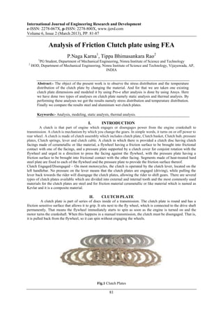
  • 1. International Journal of Engineering Research and Development e-ISSN: 2278-067X, p-ISSN: 2278-800X, www.ijerd.com Volume 6, Issue 2 (March 2013), PP. 81-87 Analysis of Friction Clutch plate using FEA P.Naga Karna1, Tippa Bhimasankara Rao2 1 PG Student, Department of Mechanical Engineering, Nimra Institute of Science and Technology 2 HOD, Department of Mechanical Engineering, Nimra Institute of Science and Technology, Vijayawada, AP, INDIA Abstract:- The object of the present work is to observe the stress distribution and the temperature distribution of the clutch plate by changing the material. And for that we are taken one existing clutch plate dimensions and modeled it by using Pro-e after analysis is done by using Ansys. Here we have done two types of analyses on clutch plate namely static analysis and thermal analysis. By performing these analyses we got the results namely stress distribution and temperature distribution. Finally we compare the results steel and aluminium wet clutch plates. Keywords:- Analysis, modeling, static analysis, thermal analysis. I. INTRODUCTION A clutch is that part of engine which engages or disengages power from the engine crankshaft to transmission. A clutch is mechanism by which you change the gears. In simple words, it turns on or off power to rear wheel. A clutch is made of clutch assembly which includes clutch plate, Clutch basket, Clutch hub, pressure plates, Clutch springs, lever and clutch cable. A clutch in which there is provided a clutch disc having clutch facings made of cerametallic or like material, a flywheel having a friction surface to be brought into frictional contact with one of the facings, and a pressure plate supported by a clutch cover for conjoint rotation with the flywheel and urged in a direction to press the facing against the flywheel, with the pressure plate having a friction surface to be brought into frictional contact with the other facing. Segments made of heat-treated hard steel plate are fixed to each of the flywheel and the pressure plate to provide the friction surface thereof. Clutch Engaged/Disengaged – On most motorcycles, the clutch is operated by the clutch lever, located on the left handlebar. No pressure on the lever means that the clutch plates are engaged (driving), while pulling the lever back towards the rider will disengage the clutch plates, allowing the rider to shift gears. There are several types of clutch plates available which are divided into external and internal tooth and the most commonly used materials for the clutch plates are steel and for friction material cerametallic or like material which is named as Kevlar and it is a composite material. II. CLUTCH PLATE A clutch plate is part of series of discs inside of a transmission. The clutch plate is round and has a friction sensitive surface that allows it to grip. It sits next to the fly wheel, which is connected to the drive shaft permanently. That means the flywheel immediately starts to spin as soon as the engine is turned on and the motor turns the crankshaft. When this happens in a manual transmission, the clutch must be disengaged. That is, it is pulled back from the flywheel, so it can spin without engaging the wheels. Fig.1 Clutch Plates 81
  • 2. Analysis of Friction Clutch plate using FEA III. TYPES OF CLUTCH PLATES  Wet Clutch Wet clutch are universal and found on any bike. Almost 99% of motorcycle manufactured uses this kind of clutch. In the wet clutch set up the entire clutch is inside the case of the bike. Here it is bathed in oil which acts like a kind of dampener. It stops the clutch from knocking on itself.  Dry Clutch The dry clutch is almost identical to the wet clutch the only difference s there are seals on the shafts that keep oil out. In the dry clutch set up the entire clutch is outside the case of the bike. There is no oil circulated in to the clutch, which result into clutch knocking on itself. Ducati‟s are almost the IV. CLUTCH PLATE MANUFACTURING PROCEDURE  First type Concurrently as seen in FIG.2 the remaining line of cut segments 14b-z advances the second segment 14b to the transfer position 71 in the shuttle assembly 70.the shuttle assembly 70 engages the second keystone segment 14b and moves in a reverse direction and transfer the second segment 14b in to a first empty pocket 97 of the adjacent second indexing fixture 92. The second indexing fixture 92 is located opposite, or at a180 degrees, from the first indexing fixture 91.Continuing with the assembly steps, the first indexing fixture 91 rotates to its next, or second, there by exposing another, or second, empty pocket, for case of illustration, each pocket will generally be referred to as 96 or 97. But it should be understood that the no. of pockets. In each indexing fixture is depended up on the no. of key stone. Friction segments that are desired on the friction plate. The shuttle assembly 70 again reverse direction, engages a third key stone segment 14c, now beginning moved in to the transfer position 71, and transfer the third segment 14c in to the second pocket 96 in the first indexing fixture 91. Concurrently, the second indexing fixture 92 rotates one position there by exposing another, or second empty pocket for receiving the fourth cut segment 14d. The sequence of alternating placements of key stone statement segments continues until all the pockets 96 and 97 in both the first 91 and second 91 indexing fixtures have been filled with key stone segment 14. Fig.2:-First type of Clutch plate manufacturing procedure  Second type Referring now to Fig.3, a plan view of the indexing fixture 91 is shown; the direction of travel is indicated by arrow z of alternating segments 14a, 14c, 14e and 14g travelling along the bottom track 74.The indexing fixture 91 comprises an indexing plate 94 having a plurality of integrally machined segment pockets 96. In the embodiment shown, there are 20 segments pockets in the indexing plate 94. However, it should be understood that the indexing plate 94 can have different no. of pockets, depending on the no. of individual segments to be positioned on a core plate. It should be further understood that the second indexing figure 92 can be substantially identical to the first indexing figure 91 will be described in detail herein. it should be further understood however, that such description also adequately describes the second indexing figure 92. The pockets 96 are slightly recessed in the indexing plate 94 to allow for accurate, vertical, radial and circumferential location of each segment 14. In certain embodiments, the depth of the pockets 96 ranges from about 0.020 to about 0.030 inches. Further, the key stone or trapezoidal, shape of the segment facilities accurate positioning of each segment 14 in the corresponding pocket 96.Each pocket 96 defines a separate vacuum port 98. typically, the cut segments have an adhesive or glued bracking such that the porosity of the cut segment is relatively low,therefore,the vacuum port 98 is used to apply a vacuum to further maintain the positioning of the segment 14 in the pocket 96(if required).in the embodiment shown, the indexing plate 94 is operatively connected to a rotating mechanism generally indicated as 100 which rotates, or indexes, the indexing plate 94.in the case of a 20-cut segment core plate, for instance, the indexing figure 91 is moved or indexed 18 degrees 82
  • 3. Analysis of Friction Clutch plate using FEA between the placement of segments since indexing accuracy is important, the rotating apparatus 100 generally comprises a servo motor and gear head assembly (not shown) which is Operatively mounted to the indexing fixture 91.Once the pockets 96 have been filled with segments 14a-t, the segments are transferred to abounding nest 140 in a suitable manner. Fig3:- Second type of Clutch plate manufacturing V. ARRANGEMENT OF CLUTCH PLATES FIG: 4 is vertical cross sectional view of a whole of a multiple disc friction clutch. In FIG: 1 , the multiple disc friction clutch is arranged between a crank shaft 1 and an input shaft 2 of a gear transmission 3 in a power transmission path from an engine (not shown) of a motor cycle to a rear wheel (not shown), and is provided with a clutch outer member 4 for take in power into the clutch, a clutch hub 5 for takeout power from the clutch, a clutch output shaft 8 integrally formed with the input shaft 2, a clutch output tube shaft (rotating member) 9 spline fitted to an outer peripheral surface of the clutch output shaft 8 in such a manner as to be immovable in an axial direction of the clutch output shaft 8, a plurality of input friction plates 10 and output friction plates 11 arranged between the clutch outer member 4 and the clutch hub 5, a pressing member (a pressure plate or a pusher plate) 12 pressing both the friction plates 10 & 11 in an axial direction of the clutch output shaft 8 (in other words an axial direction of the tube shaft 9), and coil shaped clutch spring 15 applying a pressing load to the pressing member 12. Further, in addition to each of the member for pressing or the like, there is provided a movable coupling hub 16 which is utilized for both of a pressing load increasing mechanism and a back torque limiter mechanism mentioned below, as well as transmitting a torque between the clutch hub 5 and the tube shaft 9. A shift output shaft (not shown) of the gear transmission 3 is coupled to the rear wheel in an interlocking manner, for example via a chain transmission mechanism. Fig.4:- Arrangement of clutch plates VI. CLUTCH PLATE DIMENSIONS  Addendum circle diameter = 63mm  Dedundum circle diameter = 60mm  Inner circle diameter = 51.2mm  Tooth width = 3mm 83
  • 4. Analysis of Friction Clutch plate using FEA Fig.5:- Dimensions of tooth profile and friction material profile  Tooth height = 1.5mm  Tooth thickness = 2mm  Friction material dimensions:-  Height = 4mm  Width at top =4mm  Width at bottom = 3.5mm  Depth=2mm VII. IDENTIFIED MATERIAL PROPERTIES FOR CLUTCH PLATE  Aluminium  Density: 2.70g/cm3  Thermal conductivity: 300k or 237wm-1k-1  Young‟s modulus: 70gpa  Shear modulus: 26gpa  Bulk modulus: 76gpa  Poisson‟s ratio: 0.35  Alpha: 10cm2/sec  S m: 37gpa  Steel  Density: 7.85 kg/m3  Thermal conductivity: 11.2-36. W/m-K  Young‟s modulus: 200gpa  Poisson‟s ratio: 0.27-0.3  Kevlar is the friction material Kevlar can be known as fibre reinforced polymers.  Kevlar has density 1440g/m3 and  Modulus of rigidity: 200-300gpa. VIII. MODELING OF CLUTCH PLATE USING PRO-E For modeling of a clutch plate we used the PRO-ENGINEERING, it was developed by parametric technology corporation, USA and its latest version is PRO-E WILDFIRE.4 The RAM requirement for this software is 256MB and OS requirement to operate in WINDOWS 98/2000. Procedure of Modeling of spur gear in Pro-E:-  Start  All programs  PTC Pro-E Pro-E  Select the Part module and change the dimensions in to mm  Drawn the first base circle  Extruded the base circle up to required width  Select the sketch and select the surface of the base circle  Drawn the teeth and extruded up to the same width  By using pattern command in Pro-E generated the required number of teeth 84
  • 5. Analysis of Friction Clutch plate using FEA IX. THE GENERATED MODEL OF CLUTCH PLATE USING PRO-E Fig.6:- Sketch of Clutch plate model in Pro-E Fig.7:-Solid model Fig.8:-Wire frame model X. ANALYSIS OF CLUTCH PLATE USING ANSYS For doing analysis on the clutch plate we used the ANSYS package, it is a general purpose finite element modeling package for numerically solving a wide variety of mechanical problems. Procedure of the analysis of the gear by using Ansys package:-  Start  All programs  Ansys 8.0  Ansys  Move the mechanical tool bar( for easy doing of the analysis)  Select the Ansys model i.e. static or modal , structural or thermal, and specify the dimensions that are used in the modeling, and give the analysis name  Move to setup mode to the model mode import the IGES file of that clutch plate  Apply the material properties and mesh the object  After meshing move to the loads menu and constrain the inner circle that is lie on the shaft.  Apply the loads on the clutch plate  Click on Solve now Seen the results. Fig.9:-Ansys model Fig.10:-Meshed model XI. RESULTS FOR ALUMINIUM CLUTCH PLATE  Static analysis Fig.11:- Displaced shape Fig.12:- Static equalent stress 85
  • 6. Analysis of Friction Clutch plate using FEA Table.1:-Static anaysis table for aluminum  Thermal analysis Fig.13:- Thermal flux Fig.14:- Thermal gradient XII. RESULTS FOR STEEL CLUTCH PLATE  Static analysis Fig.15:- Displaced shape Fig.16:- Static equalent stress Table.2:-Static anaysis table for steel  Thermal analysis Fig.17:- Thermal flux Fig.18:- Thermal gradient 86
  • 7. Analysis of Friction Clutch plate using FEA Figure 19: Plot Load Vs Stresses XIII. CONCLUSION The design, modeling and analysis of clutch plate is done. It is observed that the same required out put the dimensions of clutch plate are various with respect to the material. The conclusion is that for the steel material the stress intensity and displaced shape results are better than aluminium in static analysis and in thermal analysis also for the steel material the thermal flux and thermal gradient are better than aluminium. We came to know that steel is the best material for clutch plate and it will be replaced by any other composite material or an alloy or a reinforced material. ACKNOELEDGMENT I would like to thank my Guide, Mr. Tippa Bhimasankara Rao for his time and support. In addition, I would like to thank my friends for sharing their experience in PRO-E, ANSYS. Finally, I would like to thank my family for their support and putting up with me for these past few months moral and financial support during my studies. REFERENCES [1] Machine design by S.Md.Jalaludeen, Anuradha agencies. [2] Machine design by R.K. Jain [3] Machine design by „R.S. Kurmi‟ [4] Design of machine elements by „Bandri‟ [5] Machine design by R.K. Rajput [6] Design data book by Md.jalaludeen [7] Design data book by P.S.G. College [8] www.cs.cmu.edu/People/rapidproto/mechanisms/references.html [9] Mechanical Engg design – Joseph E. Shigley. [10] Design data book – P.S.G. College of technology. [11] Design data book – K.Mahadevan & K.Balaveera Reddy. [12] Analysis and approximation of contact problem [13] By Mircea Sofonia and Weimin Hann [14] Elastic contact analysis by boundary elements [15] By Susumu Takahashi [16] “A comprehensive analysis of fillet and contact stresses in straight spur gears” [17] By M.A. Alfares 87