Cisco nexus 7000 and nexus 7700
•Descargar como DOCX, PDF•
1 recomendación•1,822 vistas

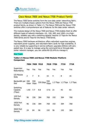
The Nexus 7000 Series switches form the core data center networking fabric. There are multiple chassis options from the Nexus 7000 and Nexus 7700 product family. The Nexus 7000 and the Nexus 7700 switches offer a comprehensive set of features for the data center network.

Recomendados
Más contenido relacionado
La actualidad más candente
La actualidad más candente (20)
Similar a Cisco nexus 7000 and nexus 7700
Similar a Cisco nexus 7000 and nexus 7700 (20)
Más de IT Tech
Más de IT Tech (20)
Último
Último (20)
Cisco nexus 7000 and nexus 7700
- 1. Cisco Nexus 7000 and Nexus 7700 Product Family The Nexus 7000 Series switches form the core data center networking fabric. There are multiple chassis options from the Nexus 7000 and Nexus 7700 product family, as shown in Table 1-5. The Nexus 7000 and the Nexus 7700 switches offer a comprehensive set of features for the data center network. The modular design of the Nexus 7000 and Nexus 7700 enables them to offer different types of network interfaces—1G, 10G, 40G, and 100G—in a high- density, scalable way with a switching capacity beyond 15 Tbps for the Nexus 7000 Series and 83 Tbps for the Nexus 7700 Series. The Nexus 7000 hardware architecture offers redundant supervisor engines, redundant power supplies, and redundant fabric cards for high availability. It is very reliable by supporting in-service software upgrades (ISSUs) with zero packet loss. It is easy to manage using the command line or through data center network manager; you can utilize NX-OS APIs to manage it. Key Topic Table 1-5 Nexus 7000 and Nexus 7700 Modular Platform Comparison 7004 7009 7010 7018 7706 7710 7718 Supervisor Redundancy Yes Yes Yes Yes Yes Yes Yes I/O Module Slots 2 7 8 16 4 8 16 Bandwidth per Slot 440 Gbps 550 Gbps 550 Gbps 550 Gbps 1.3 Tbps 1.3 Tbps 1.3 Tbps Switching Capacity (Tbps) 1.92 7.7 8.8 17.6 21 42 83 1GE Port Density 96 336 384 768 192 384 768 10GE Port Density 96 336 384 768 192 384 768 40GE Port Density 24 84 96 192 96 192 384
- 2. 100GE Port Density 4 14 16 32 48 96 192 Rack Space (RU) 7 14 21 25 9 14 26 Airflow Side- rear Side- side Frontback Side- side Frontback Frontback Frontback The Nexus 7000 and Nexus 7700 product family is modular in design with great focus on the redundancy of all the critical components; this has been applied across the physical, environmental, power, and system software aspects of the chassis. Supervisor module redundancy: The chassis can have up to two supervisor modules operating in active and standby modes. State and configuration are in sync between the two supervisors, which provide seamless and stateful switchover in the event of a supervisor module failure. NOTE: There are dedicated slots for the supervisor engines in all Nexus chassis; the supervisor modules are not interchangeable between the Nexus 7000 and Nexus 7700 chassis. Switch fabric redundancy: The fabric modules support load sharing. You can have multiple fabric modules; the Nexus 7000 supports up to five fabric modules, and Nexus 7700 supports up to six fabric modules. With the current shipping fabric cards and current I/O modules, the switches support N+1 redundancy. NOTE: The fabric modules between the Nexus 7000 and Nexus 7700 are not interchangeable. Cooling subsystem: The system has redundant fan trays. There are multiple fans on the fan trays, and any failure of one of the fans will not result in loss of service. Power subsystem availability features: The system will support the following power redundancy options: o Combined mode, where the total power available is the sum of the outputs of all the power supplies installed. (This is not redundant.) o PSU redundancy, where the total power available is the sum of all power supplies minus 1, otherwise commonly called N+1 redundancy.
- 3. o Grid redundancy, where the total power available is the sum of the power from only one input on each PSU. Each PSU has two supply inputs, allowing it to be connected to separate isolated A/C supplies. In the event of an A/C supply failure, 50% of power is secure. o Full redundancy, which is the combination of PSU redundancy and grid redundancy. In most cases, this will be the same as grid mode but will assure customers that they are protected for either a PSU or a grid failure, but not both at the same time. o PSU redundancy is the default. Modular software upgrades: The NX-OS software is designed with a modular architecture, which helps to address specific issues and minimize the system overall impact. Each service running is an individual memory-protected process, including multiple instances of a particular service that provide effective fault isolation between services and that make each service individually monitored and managed. Most of the services allow stateful restart, enabling a service that’s experiencing a failure to be restarted and resume operation without affecting other services. Cisco NX-OS in-service software upgrade (ISSU): With the NX- OS modular architecture, you can support ISSU, which enables you to do a complete system upgrade without disrupting the data plane and achieve zero packet loss. Cable management: The integrated cable management system is designed to support the cabling requirements of a fully configured system to either or both sides of the switch, allowing maximum flexibility. System-level LEDs: A series of LEDs at the top of the chassis provides a clear summary of the status of the major system components. The LEDs alert operators to the need to conduct further investigation. These LEDs report the power supply, fan, fabric, supervisor, and I/O module status. Cable management: The cable management cover and optional front module doors provide protection from accidental interference with both the cabling and modules that are installed in the system. The transparent front door allows observation of cabling and module indicator and status lights. Nexus 7000 and Nexus 7700 have multiple models with different specifications. Figure 1-18 shows these switching models, and Table 1-5 shows their specifications.
- 4. Figure 1-18 Cisco Nexus 7000 and Nexus 7700 Product Families NOTE: When you go through Table 1-5, you might wonder how the switching capacity was calculated. For example, the Nexus 7010 has eight line cards slots, so the calculation is (550 Gbps/slot) × (8 payload slots) = 4400 Gbps, (4400 Gbps) × (2 for full duplex operation) = 8800 Gbps = 8.8 Tbps system bandwidth For the Nexus 7700 Series, we’ll use the Nexus 7718 as an example. Although the bandwidth/slot shown in the table gives us 1.3 Tbps, the Nexus 7700 is capable of more than double its capacity, and that can be achieved by upgrading the fabric cards for the chassis. Therefore, if the bandwidth/slot is 2.6 Tbps, the calculation is (2.6 Tbps/slot) × (16 payload slots) = 41.6 Tbps, (4400Gbps) × (2 for full duplex operation) = 83.2 Tbps system bandwidth In some bandwidth calculations for the chassis, the supervisor slots are taken into consideration because each supervisor slot has a single channel of connectivity to each fabric card, so that makes a total of five crossbar channels. So, for example, the Cisco Nexus 7010 bandwidth is being calculated like so: (550 Gbps/slot) × (9 payload slots) = 4950 Gbps, (4950 Gbps) × (2 for full duplex operation) = 9900 Gbps = 9.9 Tbps system bandwidth Using this type of calculation, a 9-slot chassis will have 8.8 Tbps, and the 18- slot chassis will have 18.7 Tbps. Cisco Nexus 7004 Series Switch Chassis Key Topic The Cisco Nexus 7004 switch chassis shown in Figure 1-19 has two supervisor module slots and two I/O modules; the complete specification for the Nexus
- 5. 7004 is shown in Table 1-5. It is worth mentioning that the Nexus 7004 doesn’t have any fabric modules; the local I/O module fabrics are connected back-to-back to form a two-stage crossbar that interconnects the I/O modules and the supervisor engines. It has one fan tray and four 3kW power supplies. Figure 1-19 Cisco Nexus 7004 Switch Cisco Nexus 7009 Series Switch Chassis The Cisco Nexus 7009 switch chassis shown in Figure 1-20 has two supervisor module slots and seven I/O module slots; the complete specification for the Nexus 7009 is shown in Table 1-5. The Nexus 7009 switch has a single fan tray. The fan redundancy is two parts: individual fans in the fan tray and fan tray controllers. The fan controllers are fully redundant, reducing the probability of a total fan tray failure. The fans in the fan trays are individually wired to isolate any failure and are fully redundant so that other fans in the tray can take over when one or more fans fail. So, there is redundancy within the cooling system due to the number of fans. If an individual fan fails, other fans automatically run at higher speeds, and the system will continue to function, giving you time to get a spare and replace the fan tray. Figure 1-20 Cisco Nexus 7009 Switch
- 6. Although the Nexus 7009 has side-to-side airflow, there is a solution for hot aisle–cold aisle design with the 9-slot chassis. Cisco Nexus 7010 Series Switch Chassis The Cisco Nexus 7010 switch chassis shown in Figure 1-21 has two supervisor engine slots and eight I/O modules slots; the complete specification is shown in Table 1-5. There are multiple fans on the 7010 system fan trays. The fans on the trays are N+1 redundant. Any single fan failure will not result in degradation in service; the box does not overheat, and the fan tray will need replacing to restore N+1. Figure 1-21 Cisco Nexus 7010 Switch There are two system fan trays in the 7010. If either of the fan trays fails, the system will keep running without overheating as long as the operating
- 7. environment is within specifications, until the fan tray is replaced. Fan tray replacement restores N+1 redundancy. There are two fabric fan modules in the 7010; both are required for normal operation. If either fabric fan fails, the remaining fabric fan will continue to cool the fabric modules until the fan is replaced, restoring the N+1 redundancy. The system should not be operated with either the system fan tray or the fabric fan components removed, apart from the hot swap period of up to 3 minutes. Cisco Nexus 7018 Series Switch Chassis The Cisco Nexus 7018 switch chassis shown in Figure 1-22 has two supervisor engine slots and 16 I/O module slots; the complete specification is shown in Table 1-5. For the 7018 system, there are two system fan trays— one for the upper half and one for the lower half of the system. Both fan trays must be installed at all times (apart from maintenance). Each fan tray contains 12 fans that are in three rows of four. Each row cools three module slots (I/O and supervisor). The failure of a single fan will result in the other fans increasing speed to compensate, and they will continue to cool the system. The fan tray should be replaced to restore the N+1 fan resilience. Integrated into the system fan tray are the fabric fans. The fabric fans are at the rear of the system fan tray. The two fans are in series so that the air passes through both to leave the switch and cool the fabric modules. Failure of a single fabric fan will not result in a failure; the remaining fan will cool the fabric modules. Figure 1-22 Cisco Nexus 7018 Switch
- 8. NOTE: Although both system fan trays are identical, the fabric fans operate only when installed in the upper fan tray position. Fan trays are fully interchangeable, but when inserted in the lower position the fabric fans are inoperative. Cisco Nexus 7706 Series Switch Chassis The Cisco Nexus 7706 switch chassis shown in Figure 1-23 has two supervisor module slots and four I/O module slots; the complete specification is shown in Table 1-5. There are 192 10G ports, 96 40G ports, 48 100G ports, true front-to-back airflow, redundant fans, and redundant fabric cards. Figure 1-23 Cisco Nexus 7706 Switch Cisco Nexus 7710 Series Switch Chassis The Cisco Nexus 7710 switch chassis shown in Figure 1-24 has two supervisor engine slots and eight I/O module slots; the complete specification is shown in Table 1-5. There are 384 1-G ports, 192 40-G ports, 96 100-G ports, true front-to-back airflow, redundant fans, and redundant fabric cards. Figure 1-24 Cisco Nexus 7710 Switch
- 9. Cisco Nexus 7718 Series Switch Chassis The Cisco Nexus 7718 switch chassis shown in Figure 1-25 has two supervisor engine slots and 16 I/O module slots; the complete specification is shown in Table 1-5. There are 768 10G ports, 384 40G ports, 192 100G ports, true front-to-back airflow, redundant fans, and redundant fabric cards. Figure 1-25 Cisco Nexus 7718 Switch Cisco Nexus 7000 and Nexus 7700 Supervisor Module
- 10. Nexus 7000 and Nexus 7700 Series switches have two slots that are available for supervisor modules. Redundancy is achieved by having both supervisor slots populated. Table 1-6 describes different options and specifications of the supervisor modules. Key Topic Table 1-6 Nexus 7000 and Nexus 7700 Supervisor Modules Comparison Nexus 7700 Supervisor 2E Nexus 7000 Supervisor 2E Nexus 7000 Supervisor 2 Nexus 7000 Supervisor 1 CPU Dual Quad- Core Xeon Dual Quad- Core Xeon Quad-Core Xeon Dual-Core Xeon Speed (GHz) 2.13 2.13 2.13 1.66 Memory (GB) 32 32 12 8 Flash memory USB USB USB Compact Flash Fiber Channel over Ethernet (FCoE) on F2 module Yes Yes Yes No CPU Share Yes Yes Yes No Virtual Device Contexts (VDC) 8+1 admin VDC 8+1 admin VDC 4+1 admin VDC 4 Cisco Fabric Extender (FEX) Support 64 FEX/3072 ports 64 FEX/3072 ports 32 FEX/1536 ports 32 FEX/1536 ports Connectivity Management Processor (CMP) Not supported Not supported Not supported Supported Cisco Nexus 7000 Series Supervisor 1 Module The Cisco Nexus 7000 supervisor 1 module shown in Figure 1-26 is the first- generation supervisor module for the Nexus 7000. As shown in Table 1-6, the
- 11. operating system runs on a dedicated dual-core Xeon processor; dual supervisor engines run in active-standby mode with stateful switch over (SSO) and configuration synchronization between both supervisors. There are dual redundant Ethernet out-of-band channels (EOBC) to each I/O and fabric modules to provide resiliency for the communication between control and line card processors. An embedded packet analyzer reduces the need for a dedicated packet analyzer to provide faster resolution for control plane problems. The USB ports allow access to USB flash memory devices to software image loading and recovery. Figure 1-26 Cisco Nexus 7000 Supervisor 1 Module The Connectivity Management Processor (CMP) provides an independent remote system management and monitoring capability. It removes the need for separate terminal server devices for OOB management, and it offers complete visibility during the entire boot process. It has the capability to initiate a complete system restart and shutdown. Administrators must authenticate to get access to the system through CMP, and it also allows access to supervisor logs and full console control on the supervisor engine. The Cisco Nexus 7000 supervisor 1 module incorporates highly advanced analysis and debugging capabilities. The Power-on Self Test (POST) and Cisco Generic Online Diagnostics (GOLD) provide proactive health monitoring both at startup and during system operation. This is useful in detecting hardware faults. If a fault is detected, corrective action can be taken to mitigate the fault and reduce the risk of a network outage. Cisco Nexus 7000 Series Supervisor 2 Module The Cisco Nexus 7000 supervisor 2 module shown in Figure 1-27 is the next-generation supervisor module. As shown in Table 1-6, it has a quad-core CPU and 12G of memory compared to the supervisor 1 module, which has single-core CPU and 8G of memory. The supervisor 2E module is the enhanced version of the supervisor 2 module with two quad-core CPUs and 32G of memory. Figure 1-27 Cisco Nexus 7000 Supervisor 2 Module
- 12. The supervisor 2 module and supervisor 2E module have more powerful CPUs, larger memory, and next-generation ASICs that together will result in improved performance, such as enhanced user experience, faster boot and switchover times, and a higher control plane scale, such as higher VDC and FEX. Both the supervisor 2 module and supervisor 2E module support FCoE; when you are choosing the proper line card, they support CPU shares, which will enable you to carve out CPU for higher priority VDCs. Sup2E supports 8+1 VDCs. Sup2 scale is the same as Sup1; it will support 4+1 VDCs. NOTE: You cannot mix Sup1 and Sup2 in the same chassis. Note that this will be a disruptive migration requiring removal of supervisor 1. Sup2 and Sup2E can be mixed for migration only. This will be a nondisruptive migration. Cisco Nexus 7000 and Nexus 7700 Fabric Modules The Nexus 7000 and Nexus 7700 fabric modules provide interconnection between line cards and provide fabric channels to the supervisor modules. The Nexus 7000 has five fabric modules, and the Nexus 7700 has six; adding fabric modules increases the available bandwidth per I/O slot because all fabric modules are connected to all slots. Figure 1-28 shows the different fabric modules for the Nexus 7000 and Nexus 7700 products. Figure 1-28 Cisco Nexus 7000 Fabric Module
- 13. In the case of Nexus 7000, when using Fabric Module 1, which is 46 Gbps, you can deliver a maximum of 230 Gbps per slot using five fabric modules. When using Fabric Module 2, which is 110 Gbps, you can deliver a maximum of 550 Gbps per slot. In Nexus 7700, by using Fabric Module 2, which is 220 Gbps per slot, you can deliver a maximum of 1.32 Tbps per slot. All fabric modules support load sharing, and the architecture supports lossless fabric failover. In case of a failure or removal of one of the fabric modules, the remaining fabric modules will load balance the remaining bandwidth to all the remaining line cards. Nexus 7000 supports virtual output queuing (VOQ) and credit-based arbitration to the crossbar to increase performance. VOQ and credit-based arbitration allow fair sharing of resources when a speed mismatch exists to avoid head-of-line (HOL) blocking. The Nexus 7000 implements a three-stage crossbar switch. Fabric stage 1 and fabric stage 3 are implemented on the line card module, and stage 2 is implemented on the fabric module. Figure 1-29 shows how these stages are connected to each other. There are four connections from each fabric module to the line cards, and each one of these connections is 55 Gbps. When populating the chassis with six fabric modules, the total number of connections from the fabric cards to each line card is 24. It provides an aggregate bandwidth of 1.32 Tbps per slot. Figure 1-29 Cisco Nexus 7700 Crossbar Fabric
- 14. There are two connections from each fabric module to the supervisor module. These connections are also 55 Gbps. When all the fabric modules are installed, there are 12 connections from the switch fabric to the supervisor module, providing an aggregate bandwidth of 275 Gbps. NOTE: Cisco Nexus 7000 fabric 1 modules provide two 23Gbps traces to each fabric module, providing 230 Gbps of switching capacity per I/O slot for a fully loaded chassis. Each supervisor module has a single 23Gbps trace to each fabric module. Cisco Nexus 7000 and Nexus 7700 Licensing Different types of licenses are required for the Nexus 7000 and the Nexus 7700. Table 1-7 describes each license and the features it enables. Table 1-7 Nexus 7000 and Nexus 7700 Software Licensing Features Feature License Features Enterprise Services Package Open Shortest Path First (OSPF) protocol. LAN_ENTERPRISE_SERVICES_PKG Border Gateway Protocol (BGP). Intermediate System-to-Intermediate System (IS-IS) Protocol (Layer 3 only). Protocol Independent Multicast (PIM),
- 15. which includes sparse mode, bidirectional mode, and source-specific mode (SSM). Multicast Source Discovery Protocol (MSDP). Policy-based routing. Generic routing encapsulation (GRE) tunnel. Enhanced Interior Gateway Routing Protocol (EIGRP). Advanced Services Package LAN_ADVANCED_SERVICES_PKG Virtual device contexts (VDCs). VDC licenses VDC_PKG Increments four VDC licenses that enable the Cisco Nexus 7000 Series Supervisor 2 Enhanced module to support eight VDCs. Transport Services Package LAN_TRANSPORT_SERVICES_PKG Overlay Transport Virtualization (OTV). Locator/ID Separation Protocol (LISP). Scalable Services Package SCALABLE_SERVICES_PKG A single license per system enables all XL- capable I/O modules to operate in XL mode. The license increases the performance of the following features: IPv4 routes IPv6 routes ACL entries Enhanced Layer 2 Package ENHANCED_LAYER2_PKG FabricPath support on the F Series module. MPLS Services Package MPLS_PKG Multiprotocol Label Switching (MPLS). Layer 3 virtual private network (VPN). Layer 2 Ethernet over MPLS (EoMPLS). Layer 2 Virtual Private LAN Services (VPLS). Storage Enterprise Package STORAGE_ENT Inter-VSAN routing (IVR) over Fibre Channel and FCoE IVR Network Address Translation (NAT) over Fibre Channel. VSAN-based access control. Fabric binding for open systems. FCoE Services Package Fibre Channel over Ethernet (FCoE).
- 16. (FCOE_PKG) Note: You do not need the Advanced Services Package to enable the storage VDC required for FCoE. FCoE F1-Series Fibre Channel over Ethernet (FCoE) for Cisco Nexus 7000 48-port 10G SFP+ (F2). FCoE for Cisco Nexus 7700 Enhanced F2e Series 48 Port 10G (SFP+). It is worth mentioning that Nexus switches have a grace period, which is the amount of time the features in a license package can continue functioning without a license. Enabling a licensed feature that does not have a license key starts a counter on the grace period. You then have 120 days to install the appropriate license keys, disable the use of that feature, or disable the grace period feature. If at the end of the 120-day grace period the device does not have a valid license key for the feature, the Cisco NX-OS software automatically disables the feature and removes the configuration from the device. There is also an evaluation license, which is a temporary license. Evaluation licenses are time bound (valid for a specified number of days) and are tied to a host ID (device serial number). NOTE: To manage the Nexus 7000, two types of licenses are needed: the DCNM LAN and DCNM SAN, each of which is a separate license. To get the license file, you must obtain the serial number for your device by entering the show license host-id command. The host ID is also referred to as the device serial number, as shown in Example 1-1. Example 1-1 NX-OS Command to Obtain the Host ID switch# show license host-id License hostid: VDH=FOX064317SQ TIP: Use the entire ID that appears after the equal sign (=). In this example, the host ID is FOX064317SQ. After executing the copy licenses command from the default VDC, save your license file to one of four locations—the bootflash: directory, the slot0: device, the usb1: device, or the usb2: device. Perform the installation by using the install license command on the active supervisor module from the device console, as shown in Example 1-2. Example 1-2 Command Used to Install the License File switch# install license bootflash:license_file.lic Installing license ..done
- 17. You can check what licenses are already installed by issuing the command shown in Example 1-3. Example 1-3 Command Used to Obtain Installed Licenses switch# show license usage Feature Ins Lic Status Expiry Date Comments Count LAN_ENTERPRISE_SERVICES_PKG Yes - In use Never - Cisco Nexus 7000 and Nexus 7700 Line Cards Nexus 7000 and Nexus 7700 support various types of I/O modules. There are two types of I/O modules: the M-I/O modules and the F-I/O modules. Each has different performance metrics and features. Table 1-8 shows the comparison between M-Series modules. Table 1-8 Nexus 7000 and Nexus 7700 M-Series Modules Comparison N7KM1 48GS- 11L N7KM14 8GT-11L N7KM1 08X2- 12L N7KM1 32XP- 12L N7KM2 24XP- 23L N7KM2 06FQ- 23L N7KM2 02CF- 22L Line Card Family M1 M1 M1 M1 M2 M2 M2 Ports (Numbe r and Type) 48, 1GE 48, 10/100/1 000GE 8, 10GE 32, 10GE 24, 10GE 6, 40GE 2, 40/100G E Interfac e Type SFP RJ-45 X2 SFP+ SFP+ QSFP+ CFP Fabric Bandwi dth (Gbps) 46 46 80 80 240 240 240 Perform ance 60 60 120 60 120 120 120
- 18. (Mpps) NetFlo w Full/sam pled Full/samp led Full/sam pled Full/sam pled Full/sam pled Full/sam pled Full/sam pled FEX Support No No Yes Yes Yes Yes Yes Virtual PC (vPC) Support Yes Yes Yes Yes Yes Yes Yes QinQ Yes Yes Yes Yes Yes Yes Yes MPLS Support Yes Yes Yes Yes Yes Yes Yes Overlay Transp ort Virtualiz ation (OTV) Yes Yes Yes Yes Yes Yes Yes Locator /ID Separat ion Protoco l (LISP) No No No Yes No No No FCoE, FabricP ath Support No No No No No No No IEEE 1588 PTP No No No No Yes Yes Yes PONG No No No No Yes Yes Yes NOTE: From the table, you see that the M1 32-port I/O module is the only card that supports LISP. Table 1-9 shows the comparison between F-Series modules.
- 19. Table 1-9 Nexus 7000 and Nexus 7700 F-Series Modules Comparison N7KF24 8XP -25 N7KF24 8XP -25 N7KF24 8XT - 25E N7KF31 2FQ -25 N77- F248 XP - 23E N77- F348 XP - 23 N77- F324 FQ - 25 N77- F312 CK - 26 Line Card Family F2 F2e F2e F3 F2e F3 F3 F3 Chassis Supported Cisco Nexus 7000 Cisco Nexus 7000 Cisco Nexus 7000 Cisco Nexus 7000 Cisco Nexu s 7700 Cisco Nexu s 7700 Cisco Nexu s 7700 Cisco Nexu s 7700 Ports (Number and Type) 48 ports, 1 and 10GE 48 ports, 1 and 10GE 48 ports, 1 and 10GE 11-port 40GE 11- port 40GE 48- port 1 and 10GE 24- port 40GE 11- port 100G E Interface Type SFP, SFP+ SFP, SFP+ RJ-45 QSFP+, Bi-Di SFP, SFP+ SFP, SFP+ QSFP +, Bi- Di Cisco CPAK Fabric Bandwidth (Gbps) 480 480 480 480 480 480 960 1200 Performan ce (Mpps) 720 720 720 720 720 720 1440 1800 NetFlow Sampled Sampled Sampled Sampled Samp led Samp led Samp led Samp led FEX Support Yes Yes Yes Yes Yes Yes Yes Yes vPC Support Yes Yes Yes Yes Yes Yes Yes Yes FabricPath Support Yes Yes Yes Yes Yes Yes Yes Yes Layer 3 Interface Yes Yes Yes Yes Yes Yes Yes Yes
- 20. FCoE, FabricPath Support Yes Yes Yes Yes Yes Yes Yes Yes OTV, LISP, MPLS No No No Yes No Yes Yes Yes M-Series Interopera bility in Same VDC No Yes Yes Yes N/A N/A N/A N/A Cisco Nexus 7000 and Nexus 7700 Series Power Supply Options The Nexus 7000 and Nexus 7700 use power supplies with +90% power supply efficiency, reducing power wasted as heat and reducing associated data center cooling requirements. The switches offer different types of redundancy modes. They offer visibility into the actual power consumption of the total system, as well as modules enabling accurate power consumption monitoring, for the right sizing of power supplies, UPSs, and environmental cooling. Variable-speed fans adjust dynamically to lower power consumption and optimize system cooling for true load. Power redundancy: Multiple system-level options for maximum data center availability. Fully hot-swappable: Continuous system operations; no downtime in replacing power supplies. Internal fault monitoring: Detects component defect and shuts down unit. Temperature measurement: Prevents damage due to overheating (every ASIC on the board has a temperature sensor). Real-time power draw: Shows real-time power consumption. Variable fan speed: Automatically adjusts to changing thermal characteristics; lower fan speeds use lower power. Cisco Nexus 7000 and Nexus 7700 Series 3.0kW AC Power Supply Module The 3.0kW AC power supply shown in Figure 1-30 is designed only for the Nexus 7004 chassis and is used across all the Nexus 7700 Series chassis. It is a single 20-ampere (A) AC input power supply. When connecting to high line
- 21. nominal voltage (220 VAC) it will produce a power output of 3000W; connecting to low line nominal voltage (110 VAC) will produce a power output of 1400W. Figure 1-30 Cisco Nexus 7000 3.0kW AC Power Supply NOTE: Although the Nexus 7700 chassis and the Nexus 7004 use a common power supply architecture, different PIDs are used on each platform. Therefore, if you interchange the power supplies, the system will log an error complaining about the wrong power supply in the system; although technically this might work, it is not officially supported by Cisco. Cisco Nexus 7000 and Nexus 7700 Series 3.0kW DC Power Supply Module The 3.0kW DC power supply shown in Figure 1-31 is designed only for the Nexus 7004 chassis and is used across all the Nexus 7700 Series chassis. The Nexus 3.0kW DC power supply has two isolated input stages, each delivering up to 1500W of output power. Each stage uses a –48V DC connection. The unit will deliver 1551W when only one input is active and 3051W when two inputs are active. Figure 1-31 Cisco Nexus 7000 3.0kW DC Power Supply
- 22. Cisco Nexus 7000 Series 6.0kW and 7.5kW AC Power Supply Modules The 6.0kW and 7.5kW power supplies shown in Figure 1-32 are common across Nexus 7009, 7010, and 7018. They allow mixed-mode AC and DC operation, enabling migration without disruption and providing support for dual environments with unreliable AC power, with battery backup capability. Figure 1-32 Cisco Nexus 7000 6.0kW and 7.5kW Power Supplies Table 1-10 shows the specifications of both power supplies with different numbers of inputs and input types. Table 1-10 Nexus 7000 and Nexus 7700 6.0kW and 7.5kW Power Supply Specifications Power Supply Type Number of Inputs Input PowerOutput
- 23. 6.0kW Single input 220V 3000W 110V 1200W Dual input 220V 6000W 110V 2400W Dual input 110 and 220V 4200W 7.5kW Single input 220V 3750W Dual input 220V 7500W Cisco Nexus 7000 Series 6.0kW DC Power Supply Module The 6kW DC power supply shown in Figure 1-33 is common to the 7009, 7010, and 7018 systems. The 6kW has four isolated input stages, each delivering up to 1500W of power (6000W total on full load) with peak efficiency of 91% (high for a DC power supply). The power supply can be used in combination with AC units or as an all DC setup. It supports the same operational characteristics as the AC units: Redundancy modes (N+1 and N+N) Real-time power—actual power levels Single input mode (3000W) Online insertion and removal Integrated lock and On/Off switch (for easy removal) Figure 1-33 Cisco Nexus 7000 6.0kW DC Power Supply
- 24. Multiple power redundancy modes can be configured by the user: Combined mode, where the total power available is the sum of the outputs of all the power supplies installed. (This is not redundant.) PSU redundancy, where the total power available is the sum of all power supplies minus one, otherwise commonly called N+1 redundancy. Grid redundancy, where the total power available is the sum of the power from only one input on each PSU. Each PSU has two supply inputs, allowing them to be connected to separate isolated A/C supplies. In the event of an A/C supply failure, 50% of power is secure. Full redundancy, which is the combination of PSU redundancy and grid redundancy. You can lose one power supply or one grid; in most cases this will be the same as grid redundancy. Full redundancy provides the highest level of redundancy, so it is recommended. However, it is always better to choose the mode of power supply operation based on the requirements and needs. An example of each mode is shown in Figure 1-34. Figure 1-34 Nexus 6.0kW Power Redundancy Modes To help with planning for the power requirements, Cisco has made a power calculator that can be used as a starting point. It is worth mentioning that the power calculator cannot be taken as a final power recommendation.
- 25. The power calculator can be found at http://www.cisco.com/go/powercalculator. Info from http://www.ciscopress.com/articles/article.asp?p=2762085&seqNum=2 More Related Cisco Nexus 7000 and Nexus 7700 Modular Switches, the Main Chassis Cisco’s Data Center Architecture Cisco Nexus 7000 and Nexus 7700 Series Power Supply Options Cisco Nexus 7000 and Nexus 7700 Supervisor Module Cisco Nexus 7000 and Nexus 7700 Licensing Nexus 9000 vs. Nexus 7000 Cisco Nexus Positioning: 2 and 3 Tier The Latest Cisco Nexus 9000 Innovations Cisco Nexus 5500 and Nexus 5600-Model Features Cisco Nexus 5500 and Nexus 5600 Licensing Options Feature-Based Licenses for the Cisco Nexus 5000, Nexus 5500 and Nexus 5600 Series