IRJET- Battery Management System by using PWM Charge Controller
•
0 recomendaciones•13 vistas

https://irjet.net/archives/V7/i1/IRJET-V7I1347.pdf

Recomendados
Más contenido relacionado
La actualidad más candente
La actualidad más candente (20)
Similar a IRJET- Battery Management System by using PWM Charge Controller
Similar a IRJET- Battery Management System by using PWM Charge Controller (20)
Más de IRJET Journal
Más de IRJET Journal (20)
Último
Último (20)
IRJET- Battery Management System by using PWM Charge Controller
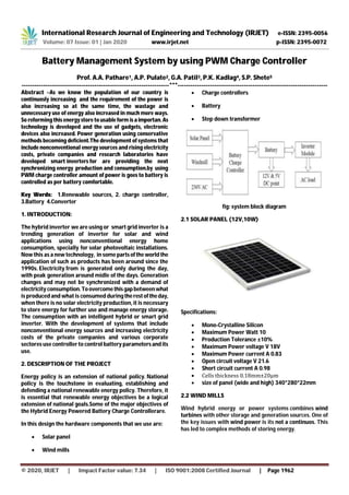
- 1. International Research Journal of Engineering and Technology (IRJET) e-ISSN: 2395-0056 Volume: 07 Issue: 01 | Jan 2020 www.irjet.net p-ISSN: 2395-0072 © 2020, IRJET | Impact Factor value: 7.34 | ISO 9001:2008 Certified Journal | Page 1962 Battery Management System by using PWM Charge Controller Prof. A.A. Pathare1, A.P. Pulate2, G.A. Patil3, P.K. Kadlag4, S.P. Shete5 ---------------------------------------------------------------------***---------------------------------------------------------------------- Abstract –As we know the population of our country is continuosly increasing and the requirement of the power is also increasing so at the same time, the wastage and unnecessary use of energy also increased in much more ways. So reforming this energy store to usable form isaimportan. As technology is developed and the use of gadgets, electronic devices also increased. Power generation using conservative methods becoming deficient.The development of systems that include nonconventional energy sources and rising electricity costs, private companies and research laboratories have developed smart inverters for are providing the next synchronizing energy production and consumption.by using PWM charge controller amount of power is goes to battery is controlled as per battery comfortable. Key Words: 1.Renewable sources, 2. charge controller, 3.Battery 4.Converter 1. INTRODUCTION: The hybrid inverter we are using or smart grid inverter is a trending generation of inverter for solar and wind applications using nonconventional energy home consumption, specially for solar photovoltaic installations. Now this as a new technology, in some partsofthe world the application of such as products has been around since the 1990s. Electricity from is generated only during the day, with peak generation around midle of the days. Generation changes and may not be synchronized with a demand of electricity consumption.Toovercomethisgapbetweenwhat is produced and what is consumed during therestoftheday, when there is no solar electricity production, it is necessary to store energy for further use and manage energy storage. The consumption with an intelligent hybrid or smart grid inverter. With the development of systems that include nonconventional energy sources and increasing electricity costs of the private companies and various corporate sectores use controller to control battery parametersand its use. 2. DESCRIPTION OF THE PROJECT Energy policy is an extension of national policy. National policy is the touchstone in evaluating, establishing and defending a national renewable energy policy. Therefore, it is essential that renewable energy objectives be a logical extension of national goals.Some of the major objectives of the Hybrid Energy Powered Battery Charge Controllerare. In this design the hardware components that we use are: Solar panel Wind mills Charge controllers Battery Step down transformer fig: system block diagram 2.1 SOLAR PANEL (12V,10W) Specifications: Mono-Crystalline Silicon Maximum Power Watt 10 Production Tolerance ±10% Maximum Power voltage V 18V Maximum Power current A 0.83 Open circuit voltage V 21.6 Short circuit current A 0.98 Cells thickness 0.18mm±20μm size of panel (wide and high) 340*280*22mm 2.2 WIND MILLS Wind hybrid energy or power systems combines wind turbines with other storage and generation sources. One of the key issues with wind power is its not a continuos. This has led to complex methods of storing energy.
- 2. International Research Journal of Engineering and Technology (IRJET) e-ISSN: 2395-0056 Volume: 07 Issue: 01 | Jan 2020 www.irjet.net p-ISSN: 2395-0072 © 2020, IRJET | Impact Factor value: 7.34 | ISO 9001:2008 Certified Journal | Page 1963 2.3 PWM Controller PWM regulators are similar to seriesregulators,but they use a transistor instead of a relay to open the array. By switching the transistor at high frequency with various modulated widths, a constantvoltagecanbemaintained. The PWM regulator self-adjusts by varying the widths (lengths) and speed of the pulses sent to the battery. Unlike the on/off charge controllers which instantaneously cut off the power transfer to minimize battery overcharging, PWM regulators act like a rapid on/off controller constantly. When the width is at 100%, the transistor is at full ON, allowing the solar array to bulk charge the battery. Whenthewidthisat0% the transistor is OFF, open circuiting the array preventing any current from flowing to the battery when the battery is fully charged .When the modulation width is at 100% or 0%, the regulator is essentially a series regulator, it is that modulation width variation that allows the PWM regulator to create a constant voltage to the battery as opposed to the on/off of the series regulator. The below figure shows an example of a PWM regulator regulating with a 70% on 30% off duty cycle. 2.4 BATTERY (12V, 7Ahr sealed lead acid) The rechargeable batteries are lead-lead dioxide systems. The dilute sulfuric acidelectrolyte is absorbed by separators and plates and thus immobilized. Should thebattery be accidentally overchargedproducinghydrogen and oxygen, special onewayvalves allow the gases to escape thus avoiding excessive pressure build-up. Otherwise, the battery is completely sealed and is, therefore, maintenance- free,leak proof and usable in any position. Fig: Battery 12V, 7Ahr sealed lead acid Features: Absorbent Glass Mat (AGM) technology for efficient gas recombination of up to 99% and freedom from electrolyte maintenance or water adding. Can be mounted in any orientation. Computer designed lead, calcium tin alloy grid for high power density. Long service life, float or cyclic Maintenance-free operation. Low self-discharge. 2.5 STEP DOWN TRANSFORMER 1) Power output. 2) Operating voltage. 3) Frequency range. 4) Efficiency and regulation. Size of core is one of the first consideration in regard of weight and volume of a transformer. Thisdependsontypeof core and winding configuration used. Generally following formula is used to find Area or Size of the Core. Xc = √ Pw / 0.87 Where, Xc = Area of cross section in square cm. Pw = Primary Wattage. For our project we require +5V output, so transformer secondary winding rating is 9V, 500mA.Sosecondarypower wattage is, P2 = 9 * 500mA =4.5Watt So, Xc = √ 4.5 / 0.87 = 2.4 Generally 10% of area should be added to the core. So ,Xc = 2.8 Now turns per volt: - Turns per volt of transformer aregiven by relation. Turns per volt = 100000 / 4.44 f * Fd * Xc Where, F= Frequency in Hz. Fd = Density in Wb / Square meter. Xc = Net area of the cross section. Following table gives the value of turns per volt for 50 Hz frequency. Generally lower thefluxdensitybetterthequality of transformer. For our project we have taken the turns per volt is 0.91 Wb / sq.m. Turns per volt = 50 / Xc = 50 / 2.8 = 17.85 Thus the turns for the primary winding are, 220 * 17.85 = 3927
- 3. International Research Journal of Engineering and Technology (IRJET) e-ISSN: 2395-0056 Volume: 07 Issue: 01 | Jan 2020 www.irjet.net p-ISSN: 2395-0072 © 2020, IRJET | Impact Factor value: 7.34 | ISO 9001:2008 Certified Journal | Page 1964 And for secondary winding, 9 * 17.85 = 160 So voltage across secondary, Pd = 9 * 1.141 = 12.727v D.C output voltage Vn across secondary is Vdc = 2 *Vn /pi = 2 * 12.727/3.14 = 8.08 V 3. CONCLUSION Our project can be used for many applications in rural areas where power availability is lessor totallyabsence.AsIndiais a developing country where energy management is a big challenge for a huge population. By using this projectwecan drive both AC and DC loads by using PWM charge controller we improve the battery efficiency and performance. REFERENCES [1] Manfred Stiebler, Wind Energy Systems for Electric Power Generation, Springer-Verlag Berlin Heidelberg, 2008 [2] M. Shaikh, Santosh B. Waghmare “A Review Paper on Electricity Generation from Solar Energy” International Journal for Research in Applied Science & Engineering Technology (IJRASET)ISSN:2321-9653;ICValue:45.98; SJ Impact Factor: 6.887 Volume 5 Issue IX, September 2017. [3] Shruti Sharma, Kamlesh Kumar Jain, AshutoshSharma a review on “Solar Cell: Research Applications”,Materials Sciences and Applications,2015,6,1145-1155Published December 2015. [4] Siva SakthiVelan G. Muthukumaran1 S. Balasubramaniyan “Windmill Power Generation Using Mult-Generator and Single Rotor (Horizontal and Vertical Blade)” Journal of Energy Technologies and Policy 2014.