SlideShare una empresa de Scribd logo
1 de 30
Design of Risers and Feeding of
Castings• A simplified diagram by putting in
references to the equations (1, 2 & 4)
there is no Equation 3, diagram not changed
• EQ(1) - Freeze Point Ratio (FPR)
FPR=X
X = (Casting Surface/Casting Volume) /
(Riser Surface/Riser Volume)
• EQ(2) - Volume Ratio (VR) (Y Axis)
VR=Y=Riser Vol/Casting Vol*
Note: The riser volume is the actual poured
volume
References - AFS Text Chapter 16; Chastain's Foundry manual Vol 2, Google
• EQ(4) - (Freeze Point Ratio) Steel
X=0.12/y-0.05 + 1.0*
*The constants are from experiments and
are empirical
Volumes, Surface Areas, Castings and
Risers...
There are relationships between all these
items and values that will help in designing
a complete mold that controls progressive
solidification, and influences directional
solidification to produce castings with
minimal porosity and shrinkage defects.
This is by ensuring that the riser(s) are the
last to solidify.
4 points about the Riser/Casting
Relationship
• 1 - Risers are attached to the
heaviest sections of the casting
• 2 - Risers are the last to solidify
• 3 - A casting that has more than
one heavy section requires at
least one riser per heavy section
• 4 - Occasionally the thermal
gradient is modified at the mold-
metal interface by the introduction
of a "Chill" that can better conduct
the heat away from the casting
and lower the solidification time
for that section.
Gating / Runner Design
• Now a look at the flow characteristics of the
metal as it enters the mold and how it fills the
casting.
Of the flow characteristics
fluidity/viscosity plays a role. Also,
velocity,
gravitational acceleration & vortex,
pressure zones,
molten alloy aspiration from the mold and
the momentum or kinetic energy of a fluid.
The demarcation point is
Re < 2000 is considered a Laminar Flow
Re > 2000 is considered a Turbulent Flow
Objective is to maintain Re below 2000.
LAMINAR FLOW- REFERENCE
TURBULENT FLOW-
REFERENCE
SEVERELY TURBULENT FLOW
Basic Components of a Gating System
• The basic components of a gating system are:
Pouring Basin,
Sprue,
Runners and
Gates that feed the casting.
The metal flows through the system in this order.
Some simple diagrams to be familiar with are:
"Crucible-Mold Interface" is where the metal
from the crucible first contacts the mold
surface. This area is lower than where the
Mouth of the Sprue is located, by having a pool
of metal from the flow will be less chaotic than
pouring from the crucible down into the sprue.
"Dross-Dam" - to skim or hold back any dross
from the crucible or what accumulated through
the act of pouring.
As the lower portion fills and the metal is
skimmed, the clean(er) metal will rise up to
meet the opening of the sprue in a more
controlled fashion.
Pouring Basin - This is the "Crucible -Mold Interface", A pouring cup and
pouring basin are not equivalents, The pouring cup is simply a larger target
when pouring out of the crucible, a Pouring Basin has several components
that aid in creating a laminar flow of clean metal into the sprue.
The basin acts as a point for the liquid metal to enter the gating system in
a laminar fashion.
Sprue Placement and Parts
The sprue is the extension of the sprue
mouth into the mold
The choke or narrowest point in the
taper is the point that would sustain a
"Head" or pressure of molten metal.
To reduce turbulence and promote
Laminar Flow, from the Pouring Basin,
the flow begins a near vertical incline
that is acted upon by gravity and with
an accelerative gravity force
Fluids in free fall tend to distort from a
columnar shape at their start into an
intertwined series of flow lines that
have a rotational vector or vortex effect
(Clockwise in the northern hemi-
sphere, and counter clockwise in the
southern hemi-sphere)...
Pressurized - is a system
where the gate and runner
cross-sectional areas are
either equal or less than
the choke cross-sectional
area;
A1= Choke = 1 unit
A2 = 1st Runner c/s
Area = 0.75 unit
A3 = 2nd Runner c/s
Area = 0.66 unit
A4 = 1st Gate = 0.33 unit
A5 = 2nd Gate = 0.33 unit
Unpressurized - The key
distinction is that the
Runner must have a c/s
area greater than the
Choke, and it would
appear that the Gate(s)
would equal or be larger
than the Runner(s).
Common Ratio's noted are;
1 : 2 : 4; 1 : 3 : 3
1 : 4 : 4; 1 : 4 : 6
• The rotational effect, though not a strong
force, is causing the cork-screwing effect
of the falling fluid. If allowed to act on the
fluid over a great enough duration or free
fall the centrifugal force will separate the
flow into droplets.
• None of the above promotes Laminar flow,
plus it aids the formation of dross and gas
pick-up in the stream that is going to feed
the casting.
Some dimensioning ratio's from
Chastain's Foundry Manual (no.2)
• 1- Choke or sprue base area is 1/5th the area of the well.
• 2- The well depth is twice the runner depth.
• 3- the Runner is positioned above the midpoint of the
well's depth
•By creating a sprue with a taper, the fluid is constrained to
retain it's shape, reducing excessive surface area development
(dross-forming property) and gas pick-up.
•The area below the sprue is the "Well". The well reduces the
velocity of the fluid flow and acts as a reservoir for the runners
and gates as they fill.
• The runner system is fed by the well
and is the path that the gates are fed
from.
• This path should be "Balanced" with the
model of heating or AC ductwork
serving as a good illustration. The
Runner path should promote smooth
laminar flow by a balanced volumetric
flow, and avoiding sharp or abrupt
changes in direction.
• The "Runner Extension" is a "Dead-
End" that is placed after the last gate.
The R-Ext acts as a cushion to absorb
the forward momentum or kinetic
energy of the fluid flow. The R-Ext also
acts as a "Dross/Gas Trap" for any
materials generated and picked-up
along the flow of the runner.
• An Ideal Runner is also proportioned
such that it maintains a constant
volumetric flow through virtually any
cross-sectional area. In the illustration,
notice that the runner becomes
proportionally shallower at the point
where an in-gate creates an alternate
path for the liquid flow.
The Runner System
The Gating System
• The Gates (in this case)
accommodate a directional
change in the fluid flow and
deliver the metal to the
Casting cavity.
• Again, the design objective
is to promote laminar flow,
the primary causes of
turbulence are sharp
corners, or un-proportioned
gate/runner sizes.
• The 2 (two) dashed blue
areas when added together
form a relationship to the
dashed blue area of the
Runner, which forms a
relationship to the Choke or
base of the Sprue Area.
• The issue of sharp corners (both inner
and outer) create turbulence, low & high
pressure zones that promote aspiration of
mold gases into the flow, and can draw
mold material (sand) into the flow. None
of this is good... By providing curved
radius changes in direction the above
effects are still at play but at a reduced
level. Sharp angles impact the
solidification process and may inhibit
"Directional Solidification" with cross-
sectional freezing...
• The image to the right is just too good a
representation to pass-up..
• By proportioning the gating system, a
more uniform flow is promoted with near
equal volumes of metal entering the mold
from all points. In an un-proportioned
system the furthest gates would feed the
most metal, while the gates closest to the
sprue would feed the least.
(this is counter to what one initially thinks).
DIRECTIONAL SOLIDIFICATION-
Formulae, Ratios and Design Equations
• What is covered so far is comprehensive, and intuitive on a
conceptual level, but the math below hopefully offers some insight
into quick approximations for simple designs, and more in-depth
calculations for complex systems.
• Computerized Flow Analysis programs are used extensively in large
Foundry operations.
• From basic concepts, designing on a state of the art system shall be
attempted:
• Continuity Equation –
• This formula allows calculation of cross-sectional areas, relative to
flow Velocity and Volumetric flow over unit time. This is with the
assumption that the fluid flow is a liquid that does NOT
compress (that applies to all molten metals).
Here, a flow passes through A1
(1" by 1", 1 sq")
The passage narrows to a cross-
sectional area A2
(.75" by .75", 0.5625 sq")
The passage expands to a cross-
sectional area A3
(1" by 1", 1 sq").
Q= Rate of Flow
(Constant - uncompressible)
V=Velocity of flow
A=Area (Cross-section)
If A1 and A2 are considered, the Area A2 is almost half of
A1, thus the velocity at A2 has to be almost double of A1.
GATING RATIO is-
Areas of Choke : Runner : Gate(s)
• The base of the Sprue and Choke are the
same.
• The ratios between the cross-sectional Area can
be grouped into either Pressurized or
Unpressurized.
• Pressurized: A system where the gate
and runner cross-sectional areas are either
equal or less than the choke cross-sectional
area.
• Areas A2 & A3 do not get
added as they are
positioned in line with
each other and flow is
successive between the
points and not
simultaneous.
• While Areas A4 & A5 are
added together as flow
does pass through these
points simultaneously.
• This example would
resolve to a pressurized
flow of 1 : 0.75 : 0.66
A1= Choke = 1 Sq Inch
A2 = 1st
Runner c/s Area = 0.75 Sq Inch
A3 = 2nd
Runner c/s Area = 0.66 Sq Inch
A4 = 1st
Gate = 0.33 Sq inch
A5 = 2nd
Gate = 0.33 Sq Inch
Unpressurized:
• The key distinction is that the Runner must have
a cross sectional area greater than the Choke,
and it would appear that the Gate(s) would equal
or be larger than the Runner(s).
• Common Ratio's noted in Chastian's Vol 2 are:
• 1 : 2 : 4
• 1 : 3 : 3
• 1 : 4 : 4
• 1 : 4 : 6
• An exception is noted in Chastain with a 1 : 8 : 6
ratio to promote dross capture in the runner
system of Aero-Space castings.
• The Continuity Equation is simplified with the
use of ratios as the velocity is inversely
proportional between any 2 adjacent ratio
values. ie H : L equates to an increase in
velocity while a L : H equates to a drop in
velocity.
• Laminar Flow is harder to control at a high
velocity than a relatively lower velocity.
• Chastain's Vol 2 has much more mathematical
expressions and calculations.

Más contenido relacionado

La actualidad más candente

Camshaft Gating and Riser System Design
Camshaft Gating and Riser System DesignCamshaft Gating and Riser System Design
Camshaft Gating and Riser System Design
ABHISHEK PATHAK
 
Continuous casting.PPT
Continuous casting.PPTContinuous casting.PPT
Continuous casting.PPT
thiru1mech
 

La actualidad más candente (19)

Casting Processes and Defects
Casting Processes and DefectsCasting Processes and Defects
Casting Processes and Defects
 
GATING SYSTEM IN CASTING
GATING SYSTEM IN CASTINGGATING SYSTEM IN CASTING
GATING SYSTEM IN CASTING
 
Camshaft Gating and Riser System Design
Camshaft Gating and Riser System DesignCamshaft Gating and Riser System Design
Camshaft Gating and Riser System Design
 
GATING SYSTEM PPT
GATING SYSTEM PPTGATING SYSTEM PPT
GATING SYSTEM PPT
 
2 ME casting &amp; solidification
2 ME  casting &amp; solidification 2 ME  casting &amp; solidification
2 ME casting &amp; solidification
 
How to calculate gate area require for hpdc die casting part
How to calculate gate area require for hpdc die casting partHow to calculate gate area require for hpdc die casting part
How to calculate gate area require for hpdc die casting part
 
Breakouts Problem during continuous casting of steel
Breakouts Problem during continuous casting of steelBreakouts Problem during continuous casting of steel
Breakouts Problem during continuous casting of steel
 
U3 p4 casting defects
U3 p4 casting defectsU3 p4 casting defects
U3 p4 casting defects
 
Metal casting by yaser elkelawy
Metal casting by yaser elkelawyMetal casting by yaser elkelawy
Metal casting by yaser elkelawy
 
casting
castingcasting
casting
 
Billet defects
Billet defectsBillet defects
Billet defects
 
Casting
CastingCasting
Casting
 
Forging
ForgingForging
Forging
 
Solidification
SolidificationSolidification
Solidification
 
45920321 defects-in-hot-rolled-products1
45920321 defects-in-hot-rolled-products145920321 defects-in-hot-rolled-products1
45920321 defects-in-hot-rolled-products1
 
Continuous casting.PPT
Continuous casting.PPTContinuous casting.PPT
Continuous casting.PPT
 
Friction stir welding
Friction stir weldingFriction stir welding
Friction stir welding
 
Steel Making: Ingot casting defects
Steel Making: Ingot casting defectsSteel Making: Ingot casting defects
Steel Making: Ingot casting defects
 
Extrusion
ExtrusionExtrusion
Extrusion
 

Destacado

Artemisia pycnocephala web show
Artemisia pycnocephala   web showArtemisia pycnocephala   web show
Artemisia pycnocephala web show
cvadheim
 

Destacado (17)

Introduktion til wordpress App Academy
Introduktion til wordpress   App AcademyIntroduktion til wordpress   App Academy
Introduktion til wordpress App Academy
 
PIRAMIDE_LA LECTURA_GOMEZ
PIRAMIDE_LA LECTURA_GOMEZPIRAMIDE_LA LECTURA_GOMEZ
PIRAMIDE_LA LECTURA_GOMEZ
 
Artemisia pycnocephala web show
Artemisia pycnocephala   web showArtemisia pycnocephala   web show
Artemisia pycnocephala web show
 
How You Earn
How You EarnHow You Earn
How You Earn
 
Gov Day Sacramento 2015 - Keynote/Overview
Gov Day Sacramento 2015 - Keynote/OverviewGov Day Sacramento 2015 - Keynote/Overview
Gov Day Sacramento 2015 - Keynote/Overview
 
2008 09
2008 092008 09
2008 09
 
Nappytimes Baby Book: Milestones
Nappytimes Baby Book: MilestonesNappytimes Baby Book: Milestones
Nappytimes Baby Book: Milestones
 
rafael
rafaelrafael
rafael
 
Aalto-1 - Haaga-Helia Happy Hacking Day
Aalto-1 - Haaga-Helia Happy Hacking DayAalto-1 - Haaga-Helia Happy Hacking Day
Aalto-1 - Haaga-Helia Happy Hacking Day
 
ITCSS: Architettura scalabile a triangolo invertito
ITCSS: Architettura scalabile a triangolo invertitoITCSS: Architettura scalabile a triangolo invertito
ITCSS: Architettura scalabile a triangolo invertito
 
Seminario 15
Seminario 15Seminario 15
Seminario 15
 
Mapping and modeling affected areas by environment and climate stresses: Egyp...
Mapping and modeling affected areas by environment and climate stresses: Egyp...Mapping and modeling affected areas by environment and climate stresses: Egyp...
Mapping and modeling affected areas by environment and climate stresses: Egyp...
 
Retos para alcanzar cobertura universal en salud
Retos para alcanzar cobertura universal en saludRetos para alcanzar cobertura universal en salud
Retos para alcanzar cobertura universal en salud
 
2ο ΔΣ Ασπροπύργου- Οραματίζομαι την αυλή του σχολείου μου με χρώματα, αρώματα...
2ο ΔΣ Ασπροπύργου- Οραματίζομαι την αυλή του σχολείου μου με χρώματα, αρώματα...2ο ΔΣ Ασπροπύργου- Οραματίζομαι την αυλή του σχολείου μου με χρώματα, αρώματα...
2ο ΔΣ Ασπροπύργου- Οραματίζομαι την αυλή του σχολείου μου με χρώματα, αρώματα...
 
Seminario n°13, protesis fija.... (2)
Seminario n°13, protesis fija.... (2)Seminario n°13, protesis fija.... (2)
Seminario n°13, protesis fija.... (2)
 
4ο ΔΣ Ασπροπύργου- Αναλαμβάνουμε δράση
4ο ΔΣ Ασπροπύργου- Αναλαμβάνουμε δράση4ο ΔΣ Ασπροπύργου- Αναλαμβάνουμε δράση
4ο ΔΣ Ασπροπύργου- Αναλαμβάνουμε δράση
 
2 Evaluación y selección de la información
2 Evaluación y selección de la información2 Evaluación y selección de la información
2 Evaluación y selección de la información
 

Similar a MANUFACTURING SCIENCE S5ME -NITC-2016-SUBTOPICS

Viscous-Laminar-Flows-Lesson-1-External-Flows-Handout (1) (1).pptx
Viscous-Laminar-Flows-Lesson-1-External-Flows-Handout (1) (1).pptxViscous-Laminar-Flows-Lesson-1-External-Flows-Handout (1) (1).pptx
Viscous-Laminar-Flows-Lesson-1-External-Flows-Handout (1) (1).pptx
Muhammad Dzaky Fawwaz
 

Similar a MANUFACTURING SCIENCE S5ME -NITC-2016-SUBTOPICS (20)

Present buk
Present bukPresent buk
Present buk
 
Lecture 1 free overfall and ogee
Lecture 1 free overfall and ogeeLecture 1 free overfall and ogee
Lecture 1 free overfall and ogee
 
Flow through pipes
Flow through pipesFlow through pipes
Flow through pipes
 
chapter_7.pdf
chapter_7.pdfchapter_7.pdf
chapter_7.pdf
 
Piping Design_Unit 1.pptx
Piping Design_Unit 1.pptxPiping Design_Unit 1.pptx
Piping Design_Unit 1.pptx
 
Presentation on notches and weirs
Presentation on notches and weirsPresentation on notches and weirs
Presentation on notches and weirs
 
Episode 44 : Flow Behavior of Granular Materials and Powders Part III
Episode 44 :  Flow Behavior of Granular Materials and PowdersPart IIIEpisode 44 :  Flow Behavior of Granular Materials and PowdersPart III
Episode 44 : Flow Behavior of Granular Materials and Powders Part III
 
4 spillways
4 spillways4 spillways
4 spillways
 
02 post
02 post02 post
02 post
 
Design Of Flow Meters
Design Of Flow MetersDesign Of Flow Meters
Design Of Flow Meters
 
Thesis Report
Thesis ReportThesis Report
Thesis Report
 
Fluid Mechanics Unit-2 (vk-ssm)
Fluid Mechanics Unit-2  (vk-ssm)Fluid Mechanics Unit-2  (vk-ssm)
Fluid Mechanics Unit-2 (vk-ssm)
 
Fluid Mech. Presentation 2nd year B.Tech.
Fluid Mech. Presentation 2nd year B.Tech.Fluid Mech. Presentation 2nd year B.Tech.
Fluid Mech. Presentation 2nd year B.Tech.
 
Episode 38 : Bin and Hopper Design
Episode 38 :  Bin and Hopper DesignEpisode 38 :  Bin and Hopper Design
Episode 38 : Bin and Hopper Design
 
Cam mech
Cam mechCam mech
Cam mech
 
orifice meter and its application_ppt
orifice meter and its application_pptorifice meter and its application_ppt
orifice meter and its application_ppt
 
INSTRUMENTATION IN EASY LANGUAGE.pdf
INSTRUMENTATION IN EASY LANGUAGE.pdfINSTRUMENTATION IN EASY LANGUAGE.pdf
INSTRUMENTATION IN EASY LANGUAGE.pdf
 
Losses in Pipe
Losses in PipeLosses in Pipe
Losses in Pipe
 
Viscous-Laminar-Flows-Lesson-1-External-Flows-Handout (1) (1).pptx
Viscous-Laminar-Flows-Lesson-1-External-Flows-Handout (1) (1).pptxViscous-Laminar-Flows-Lesson-1-External-Flows-Handout (1) (1).pptx
Viscous-Laminar-Flows-Lesson-1-External-Flows-Handout (1) (1).pptx
 
report
reportreport
report
 

Último

XXXXXXXXXXXXXXXXXXXXXXXXXXXXXXXXXXXXXXXXXXXXXXXXXXXX
XXXXXXXXXXXXXXXXXXXXXXXXXXXXXXXXXXXXXXXXXXXXXXXXXXXXXXXXXXXXXXXXXXXXXXXXXXXXXXXXXXXXXXXXXXXXXXXXXXXXXXXX
XXXXXXXXXXXXXXXXXXXXXXXXXXXXXXXXXXXXXXXXXXXXXXXXXXXX
ssuser89054b
 
Hospital management system project report.pdf
Hospital management system project report.pdfHospital management system project report.pdf
Hospital management system project report.pdf
Kamal Acharya
 
Cara Menggugurkan Sperma Yang Masuk Rahim Biyar Tidak Hamil
Cara Menggugurkan Sperma Yang Masuk Rahim Biyar Tidak HamilCara Menggugurkan Sperma Yang Masuk Rahim Biyar Tidak Hamil
Cara Menggugurkan Sperma Yang Masuk Rahim Biyar Tidak Hamil
Cara Menggugurkan Kandungan 087776558899
 
1_Introduction + EAM Vocabulary + how to navigate in EAM.pdf
1_Introduction + EAM Vocabulary + how to navigate in EAM.pdf1_Introduction + EAM Vocabulary + how to navigate in EAM.pdf
1_Introduction + EAM Vocabulary + how to navigate in EAM.pdf
AldoGarca30
 
Integrated Test Rig For HTFE-25 - Neometrix
Integrated Test Rig For HTFE-25 - NeometrixIntegrated Test Rig For HTFE-25 - Neometrix
Integrated Test Rig For HTFE-25 - Neometrix
Neometrix_Engineering_Pvt_Ltd
 

Último (20)

XXXXXXXXXXXXXXXXXXXXXXXXXXXXXXXXXXXXXXXXXXXXXXXXXXXX
XXXXXXXXXXXXXXXXXXXXXXXXXXXXXXXXXXXXXXXXXXXXXXXXXXXXXXXXXXXXXXXXXXXXXXXXXXXXXXXXXXXXXXXXXXXXXXXXXXXXXXXX
XXXXXXXXXXXXXXXXXXXXXXXXXXXXXXXXXXXXXXXXXXXXXXXXXXXX
 
AIRCANVAS[1].pdf mini project for btech students
AIRCANVAS[1].pdf mini project for btech studentsAIRCANVAS[1].pdf mini project for btech students
AIRCANVAS[1].pdf mini project for btech students
 
Generative AI or GenAI technology based PPT
Generative AI or GenAI technology based PPTGenerative AI or GenAI technology based PPT
Generative AI or GenAI technology based PPT
 
COST-EFFETIVE and Energy Efficient BUILDINGS ptx
COST-EFFETIVE  and Energy Efficient BUILDINGS ptxCOST-EFFETIVE  and Energy Efficient BUILDINGS ptx
COST-EFFETIVE and Energy Efficient BUILDINGS ptx
 
Work-Permit-Receiver-in-Saudi-Aramco.pptx
Work-Permit-Receiver-in-Saudi-Aramco.pptxWork-Permit-Receiver-in-Saudi-Aramco.pptx
Work-Permit-Receiver-in-Saudi-Aramco.pptx
 
Engineering Drawing focus on projection of planes
Engineering Drawing focus on projection of planesEngineering Drawing focus on projection of planes
Engineering Drawing focus on projection of planes
 
Wadi Rum luxhotel lodge Analysis case study.pptx
Wadi Rum luxhotel lodge Analysis case study.pptxWadi Rum luxhotel lodge Analysis case study.pptx
Wadi Rum luxhotel lodge Analysis case study.pptx
 
data_management_and _data_science_cheat_sheet.pdf
data_management_and _data_science_cheat_sheet.pdfdata_management_and _data_science_cheat_sheet.pdf
data_management_and _data_science_cheat_sheet.pdf
 
Design For Accessibility: Getting it right from the start
Design For Accessibility: Getting it right from the startDesign For Accessibility: Getting it right from the start
Design For Accessibility: Getting it right from the start
 
Online food ordering system project report.pdf
Online food ordering system project report.pdfOnline food ordering system project report.pdf
Online food ordering system project report.pdf
 
Hospital management system project report.pdf
Hospital management system project report.pdfHospital management system project report.pdf
Hospital management system project report.pdf
 
Orlando’s Arnold Palmer Hospital Layout Strategy-1.pptx
Orlando’s Arnold Palmer Hospital Layout Strategy-1.pptxOrlando’s Arnold Palmer Hospital Layout Strategy-1.pptx
Orlando’s Arnold Palmer Hospital Layout Strategy-1.pptx
 
Computer Networks Basics of Network Devices
Computer Networks  Basics of Network DevicesComputer Networks  Basics of Network Devices
Computer Networks Basics of Network Devices
 
Cara Menggugurkan Sperma Yang Masuk Rahim Biyar Tidak Hamil
Cara Menggugurkan Sperma Yang Masuk Rahim Biyar Tidak HamilCara Menggugurkan Sperma Yang Masuk Rahim Biyar Tidak Hamil
Cara Menggugurkan Sperma Yang Masuk Rahim Biyar Tidak Hamil
 
1_Introduction + EAM Vocabulary + how to navigate in EAM.pdf
1_Introduction + EAM Vocabulary + how to navigate in EAM.pdf1_Introduction + EAM Vocabulary + how to navigate in EAM.pdf
1_Introduction + EAM Vocabulary + how to navigate in EAM.pdf
 
Bhubaneswar🌹Call Girls Bhubaneswar ❤Komal 9777949614 💟 Full Trusted CALL GIRL...
Bhubaneswar🌹Call Girls Bhubaneswar ❤Komal 9777949614 💟 Full Trusted CALL GIRL...Bhubaneswar🌹Call Girls Bhubaneswar ❤Komal 9777949614 💟 Full Trusted CALL GIRL...
Bhubaneswar🌹Call Girls Bhubaneswar ❤Komal 9777949614 💟 Full Trusted CALL GIRL...
 
Block diagram reduction techniques in control systems.ppt
Block diagram reduction techniques in control systems.pptBlock diagram reduction techniques in control systems.ppt
Block diagram reduction techniques in control systems.ppt
 
Integrated Test Rig For HTFE-25 - Neometrix
Integrated Test Rig For HTFE-25 - NeometrixIntegrated Test Rig For HTFE-25 - Neometrix
Integrated Test Rig For HTFE-25 - Neometrix
 
A Study of Urban Area Plan for Pabna Municipality
A Study of Urban Area Plan for Pabna MunicipalityA Study of Urban Area Plan for Pabna Municipality
A Study of Urban Area Plan for Pabna Municipality
 
PE 459 LECTURE 2- natural gas basic concepts and properties
PE 459 LECTURE 2- natural gas basic concepts and propertiesPE 459 LECTURE 2- natural gas basic concepts and properties
PE 459 LECTURE 2- natural gas basic concepts and properties
 

MANUFACTURING SCIENCE S5ME -NITC-2016-SUBTOPICS

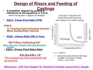
  • 1. Design of Risers and Feeding of Castings• A simplified diagram by putting in references to the equations (1, 2 & 4) there is no Equation 3, diagram not changed • EQ(1) - Freeze Point Ratio (FPR) FPR=X X = (Casting Surface/Casting Volume) / (Riser Surface/Riser Volume) • EQ(2) - Volume Ratio (VR) (Y Axis) VR=Y=Riser Vol/Casting Vol* Note: The riser volume is the actual poured volume References - AFS Text Chapter 16; Chastain's Foundry manual Vol 2, Google • EQ(4) - (Freeze Point Ratio) Steel X=0.12/y-0.05 + 1.0* *The constants are from experiments and are empirical
  • 2. Volumes, Surface Areas, Castings and Risers... There are relationships between all these items and values that will help in designing a complete mold that controls progressive solidification, and influences directional solidification to produce castings with minimal porosity and shrinkage defects. This is by ensuring that the riser(s) are the last to solidify.
  • 3. 4 points about the Riser/Casting Relationship • 1 - Risers are attached to the heaviest sections of the casting • 2 - Risers are the last to solidify • 3 - A casting that has more than one heavy section requires at least one riser per heavy section • 4 - Occasionally the thermal gradient is modified at the mold- metal interface by the introduction of a "Chill" that can better conduct the heat away from the casting and lower the solidification time for that section.
  • 4.
  • 5. Gating / Runner Design • Now a look at the flow characteristics of the metal as it enters the mold and how it fills the casting. Of the flow characteristics fluidity/viscosity plays a role. Also, velocity, gravitational acceleration & vortex, pressure zones, molten alloy aspiration from the mold and the momentum or kinetic energy of a fluid.
  • 6. The demarcation point is Re < 2000 is considered a Laminar Flow Re > 2000 is considered a Turbulent Flow Objective is to maintain Re below 2000.
  • 10. Basic Components of a Gating System • The basic components of a gating system are: Pouring Basin, Sprue, Runners and Gates that feed the casting. The metal flows through the system in this order. Some simple diagrams to be familiar with are:
  • 11. "Crucible-Mold Interface" is where the metal from the crucible first contacts the mold surface. This area is lower than where the Mouth of the Sprue is located, by having a pool of metal from the flow will be less chaotic than pouring from the crucible down into the sprue. "Dross-Dam" - to skim or hold back any dross from the crucible or what accumulated through the act of pouring. As the lower portion fills and the metal is skimmed, the clean(er) metal will rise up to meet the opening of the sprue in a more controlled fashion. Pouring Basin - This is the "Crucible -Mold Interface", A pouring cup and pouring basin are not equivalents, The pouring cup is simply a larger target when pouring out of the crucible, a Pouring Basin has several components that aid in creating a laminar flow of clean metal into the sprue. The basin acts as a point for the liquid metal to enter the gating system in a laminar fashion.
  • 12. Sprue Placement and Parts The sprue is the extension of the sprue mouth into the mold The choke or narrowest point in the taper is the point that would sustain a "Head" or pressure of molten metal. To reduce turbulence and promote Laminar Flow, from the Pouring Basin, the flow begins a near vertical incline that is acted upon by gravity and with an accelerative gravity force Fluids in free fall tend to distort from a columnar shape at their start into an intertwined series of flow lines that have a rotational vector or vortex effect (Clockwise in the northern hemi- sphere, and counter clockwise in the southern hemi-sphere)...
  • 13.
  • 14.
  • 15.
  • 16.
  • 17.
  • 18. Pressurized - is a system where the gate and runner cross-sectional areas are either equal or less than the choke cross-sectional area; A1= Choke = 1 unit A2 = 1st Runner c/s Area = 0.75 unit A3 = 2nd Runner c/s Area = 0.66 unit A4 = 1st Gate = 0.33 unit A5 = 2nd Gate = 0.33 unit Unpressurized - The key distinction is that the Runner must have a c/s area greater than the Choke, and it would appear that the Gate(s) would equal or be larger than the Runner(s). Common Ratio's noted are; 1 : 2 : 4; 1 : 3 : 3 1 : 4 : 4; 1 : 4 : 6
  • 19. • The rotational effect, though not a strong force, is causing the cork-screwing effect of the falling fluid. If allowed to act on the fluid over a great enough duration or free fall the centrifugal force will separate the flow into droplets. • None of the above promotes Laminar flow, plus it aids the formation of dross and gas pick-up in the stream that is going to feed the casting.
  • 20. Some dimensioning ratio's from Chastain's Foundry Manual (no.2) • 1- Choke or sprue base area is 1/5th the area of the well. • 2- The well depth is twice the runner depth. • 3- the Runner is positioned above the midpoint of the well's depth •By creating a sprue with a taper, the fluid is constrained to retain it's shape, reducing excessive surface area development (dross-forming property) and gas pick-up. •The area below the sprue is the "Well". The well reduces the velocity of the fluid flow and acts as a reservoir for the runners and gates as they fill.
  • 21. • The runner system is fed by the well and is the path that the gates are fed from. • This path should be "Balanced" with the model of heating or AC ductwork serving as a good illustration. The Runner path should promote smooth laminar flow by a balanced volumetric flow, and avoiding sharp or abrupt changes in direction. • The "Runner Extension" is a "Dead- End" that is placed after the last gate. The R-Ext acts as a cushion to absorb the forward momentum or kinetic energy of the fluid flow. The R-Ext also acts as a "Dross/Gas Trap" for any materials generated and picked-up along the flow of the runner. • An Ideal Runner is also proportioned such that it maintains a constant volumetric flow through virtually any cross-sectional area. In the illustration, notice that the runner becomes proportionally shallower at the point where an in-gate creates an alternate path for the liquid flow. The Runner System
  • 22. The Gating System • The Gates (in this case) accommodate a directional change in the fluid flow and deliver the metal to the Casting cavity. • Again, the design objective is to promote laminar flow, the primary causes of turbulence are sharp corners, or un-proportioned gate/runner sizes. • The 2 (two) dashed blue areas when added together form a relationship to the dashed blue area of the Runner, which forms a relationship to the Choke or base of the Sprue Area.
  • 23. • The issue of sharp corners (both inner and outer) create turbulence, low & high pressure zones that promote aspiration of mold gases into the flow, and can draw mold material (sand) into the flow. None of this is good... By providing curved radius changes in direction the above effects are still at play but at a reduced level. Sharp angles impact the solidification process and may inhibit "Directional Solidification" with cross- sectional freezing... • The image to the right is just too good a representation to pass-up.. • By proportioning the gating system, a more uniform flow is promoted with near equal volumes of metal entering the mold from all points. In an un-proportioned system the furthest gates would feed the most metal, while the gates closest to the sprue would feed the least. (this is counter to what one initially thinks).
  • 25. Formulae, Ratios and Design Equations • What is covered so far is comprehensive, and intuitive on a conceptual level, but the math below hopefully offers some insight into quick approximations for simple designs, and more in-depth calculations for complex systems. • Computerized Flow Analysis programs are used extensively in large Foundry operations. • From basic concepts, designing on a state of the art system shall be attempted: • Continuity Equation – • This formula allows calculation of cross-sectional areas, relative to flow Velocity and Volumetric flow over unit time. This is with the assumption that the fluid flow is a liquid that does NOT compress (that applies to all molten metals).
  • 26. Here, a flow passes through A1 (1" by 1", 1 sq") The passage narrows to a cross- sectional area A2 (.75" by .75", 0.5625 sq") The passage expands to a cross- sectional area A3 (1" by 1", 1 sq"). Q= Rate of Flow (Constant - uncompressible) V=Velocity of flow A=Area (Cross-section) If A1 and A2 are considered, the Area A2 is almost half of A1, thus the velocity at A2 has to be almost double of A1.
  • 27. GATING RATIO is- Areas of Choke : Runner : Gate(s) • The base of the Sprue and Choke are the same. • The ratios between the cross-sectional Area can be grouped into either Pressurized or Unpressurized. • Pressurized: A system where the gate and runner cross-sectional areas are either equal or less than the choke cross-sectional area.
  • 28. • Areas A2 & A3 do not get added as they are positioned in line with each other and flow is successive between the points and not simultaneous. • While Areas A4 & A5 are added together as flow does pass through these points simultaneously. • This example would resolve to a pressurized flow of 1 : 0.75 : 0.66 A1= Choke = 1 Sq Inch A2 = 1st Runner c/s Area = 0.75 Sq Inch A3 = 2nd Runner c/s Area = 0.66 Sq Inch A4 = 1st Gate = 0.33 Sq inch A5 = 2nd Gate = 0.33 Sq Inch
  • 29. Unpressurized: • The key distinction is that the Runner must have a cross sectional area greater than the Choke, and it would appear that the Gate(s) would equal or be larger than the Runner(s). • Common Ratio's noted in Chastian's Vol 2 are: • 1 : 2 : 4 • 1 : 3 : 3 • 1 : 4 : 4 • 1 : 4 : 6
  • 30. • An exception is noted in Chastain with a 1 : 8 : 6 ratio to promote dross capture in the runner system of Aero-Space castings. • The Continuity Equation is simplified with the use of ratios as the velocity is inversely proportional between any 2 adjacent ratio values. ie H : L equates to an increase in velocity while a L : H equates to a drop in velocity. • Laminar Flow is harder to control at a high velocity than a relatively lower velocity. • Chastain's Vol 2 has much more mathematical expressions and calculations.