Notes: Verilog Part 2 - Modules and Ports - Structural Modeling (Gate-Level Modeling)
•
1 recomendación•1,428 vistas

The Notes Verilog Part 2 includes the notes and keypoints of a reference book "Verilog HDL by Samir Palnitkar. This is the second part out of the total six parts.

Recomendados
Más contenido relacionado
La actualidad más candente
La actualidad más candente (20)
Destacado
Destacado (15)
Similar a Notes: Verilog Part 2 - Modules and Ports - Structural Modeling (Gate-Level Modeling)
Similar a Notes: Verilog Part 2 - Modules and Ports - Structural Modeling (Gate-Level Modeling) (20)
Último
Último (20)
Notes: Verilog Part 2 - Modules and Ports - Structural Modeling (Gate-Level Modeling)
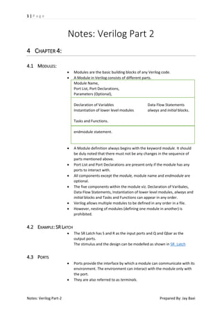
- 1. 1|Page Notes: Verilog Part 2 4 CHAPTER 4: 4.1 MODULES: Modules are the basic building blocks of any Verilog code. A Module in Verilog consists of different parts. Module Name, Port List, Port Declarations, Parameters (Optional), Declaration of Variables Instantiation of lower level modules Data Flow Statements always and initial blocks. Tasks and Functions. endmodule statement. A Module definition always begins with the keyword module. It should be duly noted that there must not be any changes in the sequence of parts mentioned above. Port List and Port Declarations are present only if the module has any ports to interact with. All components except the module, module name and endmodule are optional. The five components within the module viz. Declaration of Varibales, Data Flow Statements, Instantiation of lower level modules, always and initial blocks and Tasks and Functions can appear in any order. Verilog allows multiple modules to be defined in any order in a file. However, nesting of modules (defining one module in another) is prohibited. 4.2 EXAMPLE: SR LATCH The SR Latch has S and R as the input ports and Q and Qbar as the output ports. The stimulus and the design can be modelled as shown in SR_Latch Ports provide the interface by which a module can communicate with its environment. The environment can interact with the module only with the port. They are also referred to as terminals. 4.3 PORTS Notes: Verilog Part-2 Prepared By: Jay Baxi
- 2. 2|Page 4.4 LIST OF PORTS: A module definition can optionally have a list of ports. If module does not need to exchange any signals with the environment, there are no ports in the list. In case of a top level module TOP, which has a full adder module 4fulladd. The module 4fulladd takes input a, b, c_in as inputs and produces sum and c_out as outputs. The top level module does not need to pass or receive signals. Thus it does not have a list of ports. 4.5 PORT DECLARATION All ports in the list of ports must be declared in the module. They can be input (input port), output (output port) or inout port (bidirectional port). By default these ports are declared as wire. However, if output holds their value, they must be declared as reg. For example, in D_FF, when q was supposed to retain its value after a clock edge. Ports of input and inout cannot be declared as reg because reg variables are supposed to store values and input ports should not store values but simply reflect the changes in the external signals they are connected to. (ERROR) Internal External Inputs net reg/net Outputs reg/net reg Inouts net net Width Matching: It is legal to connect internal and external items of different sizes when making inter-module port connections. A warning is usually displayed that widths do not match. Unconnected ports: Verilog allows the ports to remain unconnected. For ports that are used only for debugging, it can be remained unconnected. The module, in this case can be instantiated by 4fulladd(SUM, , A, B, C_in) // port C_out is unconnected 4.6 CONNECTING PORTS TO EXTERNAL SIGNALS Notes: Verilog Part-2 There are two methods to connect ports to external signals 1.) Connecting Ports by ordered lists: The signals to be connected must appear in the module instantiation in the same order as the ports in the port list in the module definition 2.) Connecting Ports by name: For large modules, it is not feasible to remember the order of each port. Hence, in those cases, Verilog provides connecting external signals to ports by the port names. Prepared By: Jay Baxi
- 3. 3|Page 5 CHAPTER 5: 5.1 TRUTH TABLES OF LOGIC GATES 5.1.1 5.1.2 5.1.3 5.1.4 5.1.5 AND Gate AND 0 1 X Z 0 0 0 0 0 1 0 1 X X X 0 X X X Z 0 X X X OR Gate OR 0 1 X Z 0 0 1 X X 1 1 1 1 1 X X 1 X X Z X 1 X X NAND Gate NAND 0 1 X Z 0 1 1 1 1 1 1 0 X X X 1 X X X Z 1 X X X NOR Gate NOR 0 1 X Z 0 1 0 X X 1 0 0 0 0 X X 0 X X Z X 0 X X XOR Gate XOR 0 1 X Z 0 0 1 X X 1 1 0 X X X X X X X Z X X X X Notes: Verilog Part-2 Prepared By: Jay Baxi
- 4. 4|Page 5.1.6 5.1.7 XNOR Gate XNOR 0 1 X Z 0 1 0 X X 1 0 1 X X Z X X X X BUF Gate and NOT Gate In 0 1 X Z 5.1.8 X X X X X BUF 0 1 X X NOT 1 0 X X BUFif and NOTif The BUFif and NOTif are the gates that propagate only if their control signal is asserted. They propagate Z if the signal is deasserted. These signals are used when a signal is driven only when the control signal is asserted, this is a case when multiple drivers drive the signal //Instantiation of gates bufif1 b1 (out, in, ctrl); bufif0 b0 (out, in, ctrl); notif1 n1(out, in, ctrl); notif0 n0(out, in, ctrl); The Truth Tables of these gates are given as follows Bufif1 0 1 X Z 0 Z Z Z Z 1 0 1 X X X L H X X Z L H X X Bufif0 0 1 X Z 0 0 1 X Z 1 Z Z Z Z X L H X X Z L H X X Notif1 0 1 X Z 0 Z Z Z Z 1 1 0 X X X H L X X Z H L X X Notes: Verilog Part-2 Prepared By: Jay Baxi
- 5. 5|Page Notif0 0 1 X Z 5.1.9 0 1 0 X X Array of Instances 1 Z Z Z Z X H L X X Z H L X X For situations when there are more than one instances required, Verilog allows us to create array of instances where each instance differs from other just by the index. 5.1.10 Examples: 5.1.10.1 Gate Level Multiplexer We will design a 4-to-1 Mux with 2 select signals. Using the basic logic gates the logic diagram of a 4-to-1 Mux is given as follows The Verilog modules for the same are given in Multiplexer 5.1.10.2 4-bit Ripple Carry Adder A 4-bit full adder can be created from four 1-bit FA. The Verilog modules for the same is given in Full Adder. 5.2 GATE DELAYS Rise delay is when a delay is experienced while transition from 0, X or Z to 1. Fall delay is when a delay is experienced while transition from 1, X or Z to 0. Turn off delay is associated with a gate output transition to high impedance (Z) value from another value. Notes: Verilog Part-2 Prepared By: Jay Baxi
- 6. 6|Page Notes: Verilog Part-2 Min value: The minimum value of delay, the designer expects to have. Max value: The maximum value of delay, the designer expects to have. Typ value: The typical value of delay, the designer expects to have. Prepared By: Jay Baxi