Pcb magazine and destacker combo loader user's manual
•
1 recomendación•427 vistas

We design and manufacture automatic machine for the PCBA/SMT and Thru-hole industries in Shenzhen China. We help companies looking for low-cost equipment with smart, ROI-driven assembly equipment solutions. Email us: info@smthelp.com

Recomendados
Recomendados
Más contenido relacionado
Más de Shenzhen Southern Machinery Sales And Service Co., Ltd
Más de Shenzhen Southern Machinery Sales And Service Co., Ltd (20)
Último
Último (20)
Pcb magazine and destacker combo loader user's manual
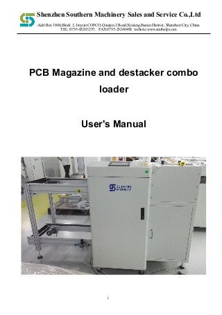
- 1. !1 Add :Rm 1806,Block 3, Jinyun COFCO, Qianjin 2 Road,Xixiang,Baoan District, Shenzhen City, China TEL: 0755-83203237; FAX:0755-23240492 website:www.smthelp.com PCB Magazine and destacker combo loader User's Manual Shenzhen Southern Machinery Sales and Service Co.,Ltd
- 2. !2 ! Be sure to carefully read this manual before use * to ensure proper use of the product. Preface Thanks to buy the company's products, the Company to express my sincere thanks. This manual hardware configuration, device operation, and maintenance of electrical diagrams have been described. Please fully understand this manual, the proper use. Although the contents of this manual seeks to correct, but if there is such as when questions or errors are found, please contact with the company. Warning: the device can only be maintained by professional and service personnel or the training of qualified personnel to operate Before powered, make sure the external input power supply with the device rated voltage and power match Please equipment of the reliable grounding all of the mechanical of this equipment, the operation should attention to personal safety Note: Please read this user manual carefully before operating this equipment, remember Caution Do not install this equipment in the vicinity electromagnetic interference source Do not modify the electric box of hardware and software programs, the transformation in danger, please keep this manual press the manual requires maintenance of equipment Although the contents of this manual are correct, please contact us if you find any doubts or errors. Shenzhen Southern Machinery Sales and Service Co. Ltd www.smthelp.com
- 3. !3 ! packing list: ⼜ Core machine ⼜ User Manual ⼜ as customers have special requirements, please refer to procurement contracts check Contents CHAPTER 1 INTRODUCTION 1.1 Overview 1.2 Technical Data Preparation before use CHAPTER 2 MACHINE OPERATION 2 .1 boot precautions 2 .2 operation screen description CHAPTER 3 DESCRIPTION OF THE PROBLEM 3.1 Faults and Maintenance 3 .1.1 deal with failure and repair equipment must do the following points: 3 .1.2 Frequently fault causes and troubleshooting CHAPTER 4 CARE AND MAINTENANCE Shenzhen Southern Machinery Sales and Service Co. Ltd www.smthelp.com
- 4. !4 ! Chapter 1 Introduction 1.1 Overview The SMT line body is sent to the board, and the board feeding mode can be switched according to the specific situation. This machine features: ! Adopt precision lead screw motor control system, stable and reliable performance. ! The stacking plate feeding mode and the frame feeding mode can be switched according to the actual situation. ! Can be adjusted according to the height of the specific front and rear position machine 1.2 Technical Parameters Project The main parameters P C B transportation direction Left to right power supply AC220 50 / 60Hz power 15 0 W. control method Touch screen plus PLC Type of transmission surface Strip PCB thickness 0.7 to 30 mm . Conveying height 880~920 ( adjustable ). Shenzhen Southern Machinery Sales and Service Co. Ltd www.smthelp.com
- 5. !5 ! Preparation before use ! Please use 220V single-phase 50Hz capacity fixed power supply above 200W ! The machine must be safely grounded and must be connected to the ground bus ! The ground wire must be well fixed to the metal part of the fuselage ! To ensure safety, it is forbidden to bring your body close to the running equipment ! Do not install the machine in dust, oil mist, conductive dust, corrosive gases, flammable gases, moisture, shock, vibration, high temperature and outdoor environment. ! Avoid using corrosive solvents to wipe the machine, neutral detergent should be used ! Please keep this price manual for future maintenance and maintenance. Notes: 1. There is no reliable grounding and there is a danger of electric shock. 2. After the air is connected, the cylinder valve will act. Please do not put your hand into the machine to prevent pinching. Shenzhen Southern Machinery Sales and Service Co. Ltd www.smthelp.com
- 6. !6 ! Chapter 2 Machine operation 2.1 Boot precautions 1. To ensure safety, physical contact with moving parts is prohibited. 2. Check for any debris in the machine. 3. Check for debris or fixture trays on the track . 2.2 Instructions 2.2.1 Boot page Figure 1 ! Description After booting up , the page shown in Figure 1 is displayed, which is the boot page. Go to the operation page Shenzhen Southern Machinery Sales and Service Co. Ltd www.smthelp.com
- 7. !7 ! 2.2.2 Operation page description: figure 2 ! Description " Reset button: Click the button to clear the alarm " Upper plate auto button: Click button in stop state, the device enters the material frame to send mode " Stop button: Click the button, the device stops running automatically, manually run And all actions " Stacking auto button: Stop button click, the device enters the stacking mode Shenzhen Southern Machinery Sales and Service Co. Ltd www.smthelp.com
- 8. !8 ! " I/O monitor button: Click to enter the input port monitoring page " Run the button manually : Click to enter the manual operation page " Parameter setting button: Click to enter the parameter setting page " Exit button: Click to enter the boot page " Alarm view button: Click to enter the alarm view page " Upper plate clear button: Click the button to clear the number of frames sent " Stacking plate clear button: Click the button to clear the number of stacked plates # Note: Before the equipment runs automatically, it needs to be set according to the relevant fixture parameters before it can run. Shenzhen Southern Machinery Sales and Service Co. Ltd www.smthelp.com
- 9. !9 ! 2.2.3 Parameter setting page description ! Input box description • Working distance setting - the number of rising grids in the frame feeding mode • Start bit setting - the number of layers sent by the first board in the frame feed mode • Out of the box induction switch time setting - in the material frame feeding mode, the material frame leaves the out of the box sensor to reach the set value time, the track stops out of the box transmission • Cylinder push-out delay alarm time setting - under the frame feeding mode, the cylinder feeding plate reaches the set time without resetting the cylinder origin, the device alarm • Delay skip box in place - the sheet feed magazine mode, the frame is transmitted to the feed bin sensor in place set time is reached the lift stop into frame relay • No board alarm delay - in the stacking board mode, after the cylinder board is completed, the track stop sensor reaches the set time and no board is detected. The device buzzer alarm prompts no board. • Outboard alarm delay - the track exit time exceeds the set time device alarm • Push forward delay time - when the stacking plate feed mode is reached, the cylinder is pushed after reaching the set time after the front push cylinder • Post-push delay time - when the stacking plate feed mode is reached, after the cylinder is pushed, the set time is reached and the cylinder is reset. • Cylinder rise delay - when the stacking plate is sent, the cylinder is pushed before the output of the cylinder reaches the set time. • Cylinder down delay - when the stack is sent to the plate mode, the cylinder drops to the set time, the track transports the PCB to the stop sensor Shenzhen Southern Machinery Sales and Service Co. Ltd www.smthelp.com
- 10. !10 ! 2.2.4 Manual page description ! Button description (The following buttons are only valid in manual operation) • Manual operation - the device stops , click the "manual page" button to enter the manual page, click the button, the device enters the manual operation state • The lifting platform rises - click the button, the lifting platform rises the number of grids • The lifting platform is lowered - click the button, the lifting platform is lowered by the number of grids • Advance frame - click the button and the lift rises to the upper limit • Down frame - click the button, the lift down to the lower limit • Into the frame - the lifting platform is at the upper limit, click the button, the lifting platform is sent into the frame Shenzhen Southern Machinery Sales and Service Co. Ltd www.smthelp.com
- 11. !11 ! • Out of the box - the lifting platform is at the lower limit, click the button, the lifting platform is sent out • Clamping - click the button to clamp the cylinder action • Push plate - when the lift is in the proper position, click the button, push the plate cylinder action • Rise - click the button, the stack structure rises the cylinder action • Pushing the cylinder forward - click the button, push the cylinder action before the stacking structure • Push the cylinder backwards - click the button, push the cylinder after the stacking structure • Stacking plate clamping - click the button, the stacking structure clamps the cylinder action 2.25 input and output monitoring instructions $ Monitors the status of each sensor and button, green is on Shenzhen Southern Machinery Sales and Service Co. Ltd www.smthelp.com
- 12. !12 ! $ It can monitor the output control status of the program, green is the output, if there is output, there is no response, please contact the supplier. Shenzhen Southern Machinery Sales and Service Co. Ltd www.smthelp.com
- 13. !13 ! Chapter 3 Troubleshooting and Troubleshooting 1. The principles familiar with the equipment and electrical schematics. 2. Familiar with the installation position of each mechanical device and electrical equipment in the equipment, and understand its performance and role. 3. Correctly analyze the cause of the fault. 4. Find the faulty part and the failed component 5. Targeted maintenance. Frequently the cause of the fault and troubleshooting Notes: Repair or replacement of electrical components disconnect the power, the charging operation is prohibited. Fault content cause of issue Approach Jam into the board The height of the left side is different from the height of the upper computer. Use a spanner wrench to adjust the threaded rod to make the height consistent The main power switch indicator is off. The switch is broken, the wire is loose, the power cord Open circuit Unplug the plug and open it to make the panel. Check if the thread is loose. If it is loose and re-crimped, if it is not loose, please replace the button Shenzhen Southern Machinery Sales and Service Co. Ltd www.smthelp.com
- 14. !14 ! Chapter 4 Maintenance and Maintenance % Check the transport of steel strap is too loose, keep the conveyor belt clean. % Wipe off the dirty oil with a cloth or paper and then lubricate the ball screw. % Test whether the delivery of the product is smooth. % Check the track for wear. % Oil the screw every week Shenzhen Southern Machinery Sales and Service Co. Ltd www.smthelp.com