SlideShare una empresa de Scribd logo
1 de 35
Descargar para leer sin conexión
99719-18100
For use with S4Q2, S4S and K15/K21/K25 Engine
Service Manuals.
FG10N F25C-05001-up
FG15N F25C-55001-up
FG15ZN F34-52001-up
FG18N F25C-75001-up
FG18ZN F34-72001-up
FG20CN F34-22001-up
FG20N F17D-10001-up
FG20ZN F35-10001-up
FG25N F17D-60001-up
FG25ZN F35-60001-up
FG30N F13F-40001-up
FG35AN F13F-60001-up
FD10N F16D-04001-up
FD15N F16D-54001/64001-up
FD18N F16D-74001/84001-up
FD20CN F16D-24001/28001-up
FD20N F18C-20001/40001-up
FD25N F18C-70001/90001-up
FD30N F14E-10001/20001-up
FD35AN F14E-80001/90001-up
FGE15N F34-00001/19001-up
FGE18N F34-40001/49001-up
FGE20CN F34-30001/39001-up
FGE20N F17D-20001/38001-up
FGE20ZN F35-20001/38001-up
FGE25N F17D-70001/88001-up
FGE25ZN F35-70001/88001-up
FGE30N F13F-10001/20001-up
FGE35AN F13F-80001/90001-up
Chassis & Mast MC/FC
Service Manual
1
Pub. No. 99719-18100
FOREWORD
This service manual is a guide for servicing Mitsubishi forklift trucks. For your convenience the instructions are
grouped by systems as a ready reference.
The long productive life of your lift truck(s) depends on regular and proper servicing. Servicing consistent with what
you will learn by reading this service manual.
Read the respective sections of this manual carefully and familiarize yourself with all of the components before
attempting to start a test, repair or rebuild job.
The descriptions, illustrations and specifications contained in this manual are for trucks with serial numbers in effect
at the time of printing.
Mitsubishi Forklift Trucks reserves the right to change specifications or designs without notice and without incurring
obligations.
The trucks listed in this manual are powered by K15, K21 or K25 gasoline engines or S4Q2/S4S diesel engines.
For engine servicing, please refer to the applicable engine service manual.
K15, K21 or K25 Gasoline engine
S4Q2, S4S Diesel engine
<Safety Related Signs>
Indicates a specific potential hazard resulting in serious
bodily injury or death.
Indicates a potentially hazardous situation which, if not
avoided, may result in death or serious injury or damage to
the machine.
Indicates a condition that can cause damage to, or shorten
service life of, the machine.
WARNING
CAUTION
NOTE
3
SAFETY
The proper and safe lubrication and maintenance
for these lift trucks, recommended by Mitsubishi
Forklift Trucks, are outlined in the OPERATION &
MAINTENANCE MANUAL.
Read and understand the OPERATION & MAINTE-
NANCE MANUAL before performing any lubrica-
tion or maintenance on these trucks.
Improper performance of lubrication or mainte-
nance procedures is dangerous and could result
in injury or death.
The serviceman or mechanic may be unfamiliar with
many of the systems on this truck. This makes it
important to use caution when performing service
work. A knowledge of the system and/or components
is important before the removal or disassembly of any
component.
Because of the size of some of the truck components,
the serviceman or mechanic should check the weights
noted in this Manual. Use proper lifting procedures
when removing any components.
Following is a list of basic precautions that should
always be observed.
(1) Read and understand all warning plates and
decals on the truck before operating, lubricating or
repairing the product.
(2) Always wear protective glasses and protective
shoes when working around trucks. In particular,
wear protective glasses when pounding on any
part of the truck or its attachments with a hammer
or sledge. Use welders gloves, hood/goggles,
apron and other protective clothing appropriate to
the welding job being performed. Do not wear
loose fitting or torn clothing. Remove all rings from
fingers when working on machinery.
(3) Do not work on any truck that is supported only by
lift jacks or a hoist. Always use blocks or jack
stands to support the truck before performing any
disassembly.
(4) Lower the forks or other implements to the ground
before performing any work on the truck. If this
cannot be done, make sure the forks or other
implements are blocked correctly to prevent them
from dropping unexpectedly.
Do not operate these trucks unless you have read
and understood the instructions in the OPERA-
TION & MAINTENANCE MANUAL. Improper truck
operation is dangerous and could result in injury
or death.
(5) Use steps and grab handles (if applicable) when
mounting or dismounting a truck. Clean any mud
or debris from steps, walkways or work platforms
before using. Always face truck when using steps,
ladders and walkways. When it is not possible to
use the designed access system, provide ladders,
scaffolds, or work platforms to perform safe repair
operations.
(6) To avoid back injury, use a hoist when lifting com-
ponents which weigh 23 kg or more. Make sure all
chains, hooks, slings, etc., are in good condition
and are of the correct capacity. Be sure hooks are
positioned correctly. Lifting eyes are not to be side
loaded during a lifting operation.
(7) To avoid burns, be alert for hot parts on trucks
which have just been stopped and hot fluids in
lines, tubes and compartments.
(8) Be careful when removing cover plates. Gradually
back off the last two bolts or nuts located at oppo-
site ends of the cover or device and pry cover
loose to relieve any spring or other pressure,
before removing the last two bolts or nuts com-
pletely.
(9) Be careful when removing filler caps, breathers
and plugs on the truck. Hold a rag over the cap or
plug to prevent being sprayed or splashed by liq-
uids under pressure. The danger is even greater if
the truck has just been stopped because fluids
can be hot.
(10)Always use tools that are in good condition and
be sure you understand how to use them before
performing any service work.
(11)Reinstall all fasteners with same part number. Do
not use a lesser quality fastener if replacements
are necessary.
(12)If possible, make all repairs with the truck parked
on a level, hard surface. Block truck so it does not
roll while working on or under truck.
WARNING WARNING
4
(13)Disconnect battery and discharge any capacitors
(electric trucks) before starting to work on truck.
Hang “Do not Operate” tag in the Operator’s Com-
partment.
(14)Repairs, which require welding, should be per-
formed only with the benefit of the appropriate ref-
erence information and by personnel adequately
trained and knowledgeable in welding proce-
dures. Determine type of metal being welded and
select correct welding procedure and electrodes,
rods or wire to provide a weld metal strength
equivalent at least to that of parent metal.
(15)Do not damage wiring during removal operations.
Reinstall the wiring so it is not damaged nor will it
be damaged in operation by contacting sharp cor-
ners, or by rubbing against some object or hot
surface. Place wiring away from oil pipe.
(16)Be sure all protective devices including guards
and shields are properly installed and functioning
correctly before starting a repair. If a guard or
shield must be removed to perform the repair
work, use extra caution.
(17)Always support the mast and carriage to keep
carriage or attachments raised when maintenance
or repair work is performed, which requires the
mast in the raised position.
(18)Loose or damaged fuel, lubricant and hydraulic
lines, tubes and hoses could cause fires. Do not
bend or strike high pressure lines or install ones
which have been bent or damaged. Inspect lines,
tubes and hoses carefully. Do not check for leaks
with your hands. Pin hole (very small) leaks could
result in a high velocity oil stream that will be invis-
ible close to the hose. This oil could penetrate the
skin and cause personal injury. Use cardboard or
paper to locate pin hole leaks.
(19)Tighten connections to the correct torque. Make
sure that all heat shields, clamps and guards are
installed correctly to avoid excessive heat, vibra-
tion or rubbing against other parts during opera-
tion. Shields that protect against oil spray onto hot
exhaust components in event of a line, tube or
seal failure, must be installed correctly.
(20)Relieve all pressure in air, oil or water systems
before any lines, fittings or related items are dis-
connected or removed. Always make sure all
raised components are blocked correctly and be
alert for possible pressure when disconnecting
any device from a system that utilizes pressure.
(21)Do not operate a truck if any rotating part is dam-
aged or contacts any other part during operation.
Any high speed rotating component that has been
damaged or altered should be checked for bal-
ance before reusing.
5
HOW TO USE THIS MANUAL
Lift truck models covered in this manual
MC Truck (Mechanical Control System)
Mechanically controlled hydraulic system (conventional lever system)
FC Truck (Finger-tip Control System)
Electronically controlled hydraulic system
Gasoline-Engine Trucks (FGE, FG)....... Trucks Equipped with K21 or K25 Gasoline Engine
Diesel-Engine Trucks (FD).................... Trucks Equipped with K21 or K25 Diesel Engine
Powershift Trucks................................... Trucks Equipped with Powershift Transmission
Manual Transmission Trucks................. Trucks Equipped with Manual Transmission
(2 Types of Clutch; Dry and Wet)
213443
MC Truck
FC Truck
Lever
Control valve
FC lever box
VCM Controller
Electric wiring
Electromagnetic control valve
Flow regulator valve
Output unit
Input unit
6
HOW TO USE THIS MANUAL (continued)
(Removal, Installation, Assembly and Disassembly)
Disassembly diagram (example)
Suggestions for Disassembly
Output shaft, Removing
Remove output shaft using a special tool.
A: Standard value
B: Repair or Service Limit
1
2
213445
Sequence
1 Cover, Bolt, Washer (part name)
2 Snap ring (part name)
213446
Service Data
Gear Backlash
A 0.11 to 0.28 mm
B 0.5 mm
7
Symbols and abbreviations
Units
(1) SI Units are used in this manual.
(2) The following table shows the conversion of SI
unit and customary unit.
OP Option
R1/4 Taper pipe thread (external) 1/4 inch (formerly PT1/4)
RC1/8 Taper pipe thread (external) 1/4 inch (formerly PT1/8)
G1/4A Straight pipe thread (external) 1/4 inch (formerly PF1/4-A)
Rp1/8 Straight pipe thread (internal) 1/8 inch (formerly PS1/8)
Item SI unit Customary unit
Force
1 N 0.102 kgf
1 lbf 0.4536 kgf
Pressure
1 kPa 0.0102 kgf/cm2
1 psi 0.0703 kgf/cm2
Torque
1 N·m 0.102 kgf·m
1 lbf·ft 0.1383 kgf·m
CHAPTER INDEX
CHAPTER INDEX
CHAPTER INDEX Items
GENERAL INFOMATION
Truck Models Covered, Serial Number Locations,
Dimensions, Technical Data
COOLING SYSTEM Fan Belt Removal and Installation, Fan Belt Tension
ELECTRICAL SYSTEM
Console Box, Chassis Electrical Devices,
Battery Maintenance, Electrical Schematic
CONTROLLERS
Main Functions of Controller, Input/Output Monitor,
Error Codes and Troubleshooting
POWER TRAIN Removal and Installation of Power Line
CLUTCHES Dry-Type Clutch, Wet-Type Clutch
MANUAL TRANSMISSION Structure, Removal and Installation of Transmission
POWERSHIFT TRANSMISSION
Torque Converter,
Singe Speed Powershift Transmission Control Valve,
Automatic Two-Speed Transmission
FRONT AXLE AND
REDUCTION DIFFERENTIAL
Front Tire, Front Axle, Reduction, Differential
REAR AXLE Rear Axle, Rear Tire
BRAKE SYSTEM Master Cylinder, Wheel Brake, Brake Booster
STEERING SYSTEM Steering Gear, Power Cylinder, Flow Divider
HYDRAULIC SYSTEM
Tank, Pump, Control Valve, Lift and Tilt Cylinders,
Flow Regulator Valve, Down Safety Valve
MAST AND FORKS Simplex and Duplex Masts, Triplex Mast
SERVICE DATA
Maintenance Standard, Maintenance Schedule,
Periodic Replacement Parts, Lubrication Instruction,
Special Tool Needed
1
2
3
4
5
6
7
8
9
10
11
12
13
14
15
1
Chapter 1 GENERAL INFORMATION
1. Model View............................................................................................... 1-1
2. Truck Models Covered............................................................................ 1-2
3. Serial Number Locations........................................................................ 1-3
4. Dimensions.............................................................................................. 1-4
5. Technical Data......................................................................................... 1-5
6. Performance ............................................................................................ 1-7
1-1
GENERAL INFORMATION
Chapter 1 GENERAL INFORMATION
1. Model View
213447
MC truck
213448
FC truck
1-2
GENERAL INFORMATION
2. Truck Models Covered
This Service Manual provides servicing and maintenance information for the following trucks:
(FC type is used in torque converter model only.)
Note: Characters at the end of truck model should be read as follows:
(F) : FC Truck
None : MC Truck
Z : High-power engine model
C : Short wheel base model
Engine mounted Gasoline-engine truck
Dual fuel gasoline/
LPG-engine truck
Diesel-engine truck
Non-electric controlled MC / FC MC / FC MC / FC
Electric controlled MC / FC MC / FC -
Truck type
Electric controlled gasoline engine,
Electric controlled dual fuel gasoline/
LPG engine models
Non-electric controlled diesel engine models
Non-electric controlled gasoline engine,
Non-electric controlled dual fuel gasoline/
LPG engine models
Truck model Serial number
Engine
mounted
Truck model Serial number
Engine
mounted
1 ton class
FG10N F25C-05001 to K15 FD10N F16D-04001 to S4Q2
FG15N F25C-55001 to K15 FD15N F16D-54001 to S4Q2
FG15ZN F34-52001 to K21 FD15N(F) F16D-64001 to S4Q2
FGE15N F34-00001 to K21E FD18N F16D-74001 to S4Q2
FGE15N(F) F34-19001 to K21E FD18N(F) F16D-84001 to S4Q2
FG18N F25C-75001 to K15 FD20CN F16D-24001 to S4Q2
FG18ZN F34-72001 to K21 FD20CN(F) F16D-28001 to S4Q2
FGE18N F34-40001 to K21E - - -
FGE18N(F) F34-49001 to K21E - - -
FG20CN F34-22001 to K25 - - -
FGE20CN F34-30001 to K25E - - -
FGE20CN(F) F34-39001 to K25E - - -
2 ton class
FG20N F17D-10001 to K21 FD20N F18C-20001 to S4S
FG20ZN F35-10001 to K25 FD20N(F) F18C-40001 to S4S
FGE20N F17D-20001 to K21E FD25N F18C-70001 to S4S
FGE20N(F) F17D-38001 to K21E FD25N(F) F18C-90001 to S4S
FGE20ZN F35-20001 to K25E - - -
FGE20ZN(F) F35-38001 to K25E - - -
FG25N F17D-60001 to K21 - - -
FG25ZN F35-60001 to K25 - - -
FGE25N F17D-70001 to K21E - - -
FGE25N(F) F17D-88001 to K21E - - -
FGE25ZN F35-70001 to K25E - - -
FGE25ZN(F) F35-88001 to K25E - - -
3 ton class
FG30N F13F-40001 to K25 FD30N F14E-10001 to S4S
FGE30N F13F-10001 to K25E FD30N(F) F14E-20001 to S4S
FGE30N(F) F13F-20001 to K25E FD35AN F14E-80001 to S4S
FG35AN F13F-60001 to K25 FD35AN(F) F14E-90001 to S4S
FGE35AN F13F-80001 to K25E - - -
FGE35AN(F) F13F-90001 to K25E - - -
1-3
GENERAL INFORMATION
3. Serial Number Locations
213449
Chassis Serial NumberName Plate Gasoline Engine Serial Number
Diesel Engine Serial Number
(2, 3 ton classes)
Diesel Engine Serial Number
(1 ton class and FD20N–25N)
Transmission Serial Number
(Powershift Transmission Truck)
Transmission Serial Number
(Manual Transmission Truck)
Mast Serial Number
1-4
GENERAL INFORMATION
4. Dimensions
213450
A
B
H
J
E
D N
P
M
F
I
L
O
KCG
1-5
GENERAL INFORMATION
5. Technical Data
Unit: mm
Truck model
class 1 ton class
Gasoline-
engine truck
FG10N FG15N FG18N FG20CN
FGE15N FGE18N FGE20CN
FG15ZN FG18ZN
Diesel-engine
truck
FD10N FD15N FD18N FD20CN
A Maximum lift 3000 3000 3000 3000
B Free lift height 115 115 115 120
C Fork spread 200 to 920 200 to 920 200 to 920 220 to 920
D Fork length 770 920 920 920
E Tilt angle (forward – backward) 6-12 6-12 6-12 6-12
F Overall length 2980 3180 3220 3280
G
Overall width
(outside-to-
outside of tires)
Single 1065 1065 1065 1065
Double 1330 1330 1330 -
H Overall height (with mast lowered) 1990 1990 1990 1990
I Height of the overhead guard 2065 2065 2065 2065
J Overall height (with mast extended) 4055 4055 4055 4055
K
Tread
(front wheel)
Single 890 890 890 890
Double 1025 1025 1025 -
L Tread (rear wheel) 900 900 900 900
M Wheel base 1400 1400 1400 1400
N Front overhang 400 400 400 415
O Minimum turning radius 1910 1950 1980 2020
P
Under clearance
(at center of frame)
150 150 150 150
1-6
GENERAL INFORMATION
Unit: mm
Truck model
class 2 ton class 3 ton class
Gasoline-
engine truck
FG20N FG25N FG30N FG35AN
FGE20N FGE25N FGE30N FGE35AN
FG20ZN FG25ZN
FGE20ZN FGE25ZN
Diesel-engine
truck
FD20N FD25N FD30N FD35AN
A Maximum lift 3000 3000 3000 3000
B Free lift height 140 145 145 145
C Fork spread 220 to 1000 220 to 1000 250 to 1000 250 to 1000
D Fork length 920 920 1070 1070
E Tilt angle (forward – backward) 6-12 6-12 6-12 6-12
F Overall length 3410 3625 3795 3860
G
Overall width
(outside-to-
outside of tires)
Single 1150 1150 1275 1290
Double 1480 1480 1490 1490
H Overall height (with mast lowered) 1990 1990 2015 2130
I Height of the overhead guard 2074 2074 2093 2103
J Overall height (with mast extended) 4055 4055 4055 4055
K
Tread
(front wheel)
Single 960 960 1060 1060
Double 1140 1140 1140 1140
L Tread (rear wheel) 980 980 980 980
M Wheel base 1600 1600 1700 1700
N Front overhang 455 460 495 495
O Minimum turning radius 2200 2230 2380 2440
P
Under clearance
(at center of frame)
160 160 190 200
1-7
GENERAL INFORMATION
6. Performance
Truck
model
class 1 ton class
Gasoline-
engine truck
FG10N FG15N FG18N FG20CN
FGE15N FGE18N FGE20CN
FG15ZN FG18ZN
Diesel-engine
truck
FD10N FD15N FD18N FD20CN
Capacity kg 1000 1500 1750 2000
Load center mm 500 500 500 500
Lift speed
Loaded mm/s
490 (FG10N)
490 (FG15N)
630 (FGE15N)
570 (FG15ZN)
490 (FG18N)
630 (FGE18N)
570 (FG18ZN)
570 (FG20CN)
630 (FGE20CN)
630 (FD10N) 630 (FD15N) 630 (FD18N) 630 (FD20CN)
Unloaded mm/s
560 (FG10N)
560 (FG15N)
650 (FGE15N)
650 (FG15ZN)
560 (FG18N)
650 (FGE18N)
650 (FG18ZN)
650 (FG20CN)
650 (FGE20CN)
690 (FD10N) 690 (FD15N) 690 (FD18N) 690 (FD20CN)
Travel speed
(Powershift
Truck)
Loaded km/h 19.0 19.0 19.0 19.0
Unloaded km/h 19.5 19.5 19.5 19.5
1-8
GENERAL INFORMATION
Truck
model
class 2 ton class 3 ton class
Gasoline-
engine truck
FG20N FG25N FG30N FG35AN
FGE20N FGE25N FGE30N FGE35AN
FG20ZN FG25ZN
FGE20ZN FGE25ZN
Diesel-engine
truck
FD20N FD25N FD30N FD35AN
Capacity kg 2000 2500 3000 3500
Load center mm 500 500 500 500
Lift speed
Loaded mm/s
520 (FG20N)
580 (FGE20N)
580 (FG20ZN)
640 (FGE20ZN)
520 (FG25N)
580 (FGE25N)
580 (FG25ZN)
640 (FGE25ZN)
460 (FG30N)
510 (FGE30N)
390 (FG35AN)
430 (FGE35AN)
630 (FD20N) 630 (FD25N) 500 (FD30N) 420 (FD35AN)
Unloaded mm/s
600 (FG20N)
590 (FGE20N)
660 (FG20ZN)
660 (FGE20ZN)
600 (FG25N)
590 (FGE25N)
660 (FG25ZN)
660 (FGE25ZN)
530 (FG30N)
530 (FGE30N)
450 (FG35AN)
440 (FGE35AN)
660 (FD20N) 660 (FD25N) 530 (FD30N) 450 (FD35AN)
Travel speed
(Powershift
Truck)
Loaded km/h 19.0 19.0 19.0 19.0
Unloaded km/h 19.5 19.5 19.5 19.5
2
Chapter 2 COOLING SYSTEM
1. Specifications.......................................................................................... 2-1
2. Structure .................................................................................................. 2-2
3. Removal and Installation........................................................................ 2-3
3.1 Fan Belt Removal....................................................................................................2-3
3.2 Suggestions for Removal ........................................................................................2-3
3.3 Installation ...............................................................................................................2-4
4. Inspection and Adjustment.................................................................... 2-5
4.1 Fan Belt Inspection..................................................................................................2-5
4.2 Fan Belt Tension .....................................................................................................2-5
4.3 Connecting Hoses ...................................................................................................2-5
4.4 Unit Layout ..............................................................................................................2-6
4.5 Coolant ....................................................................................................................2-6
4.6 Radiator Cap ...........................................................................................................2-6
2-1
COOLING SYSTEM
Chapter 2 COOLING SYSTEM
1. Specifications
Items
Truck type
1 ton class 2 ton class 3 ton class
Cooling system
Cooling method Water-cooled, forced circulation
Radiator Corrugated fin (pressure) type
Water pump Centrifugal type
Thermostat Wax pellet type
2-2
COOLING SYSTEM
2. Structure
213451
S4Q2
S4S
Hose layout
S4Q2 engine
K15, K21,
K25 engines
S4S engine
Lower hose
Shroud
Upper hose
Radiator
Reservoir tank
K15, K21, K25
Fan (directly coupled to engine)
2-3
COOLING SYSTEM
3. Removal and Installation
3.1 Fan Belt Removal
3.2 Suggestions for Removal
(1) Loosen the tension pulley lock bolt by three or
four turns.
If the bolt is loosened insufficiently, the tension
pulley will not move.
Note: Do not loosen the lock bolt to such an extent that
the bolt would be removed.
(2) Move the tension pulley fully toward the fan, then
remove the belt.
1 Tension pulley assembly, bolt
2 Belt
213452
Engine
Fan
21
213453
Tension
pulley
Fan
2-4
COOLING SYSTEM
3.3 Installation
To install, follow the removal sequence in reverse.
Also follow the instructions given below.
(1) Before installing the belt, turn the fan to check for
smooth rotation. Replace the bearing if it gener-
ates abnormal sound.
(2) After installing the belt, push it to make sure that
the tension pulley moves, then tighten the pulley
lock bolt firmly.
2-5
COOLING SYSTEM
4. Inspection and Adjustment
4.1 Fan Belt Inspection
(1) Check the belt for contamination from oil, grease
or dust. Replace the belt if required. When the
contamination is slight, clean the belt with a rag or
paper towel. Do not use gasoline, oil or any other
solvent to clean the belt.
(2) During the engine overhaul or belt tension adjust-
ment, check the condition of the belt. Replace the
belt if it has any damage.
4.2 Fan Belt Tension
Apply a force of 98 N (10 kgf) perpendicularly to the
belt at a point midway between the fan pulley and ten-
sion pulley. Adjust the belt tension between 11 to 13
mm.
4.3 Connecting Hoses
When connecting the hoses to the radiator, fit their
ends fully on the fittings and secure them with clamps.
Make sure that each hose is correctly connected and
over the flare of the fitting.
213454
Tension
pulley
Fan pulley
213455
Hose
2-6
COOLING SYSTEM
4.4 Unit Layout
4.5 Coolant
Fill the radiator with coolant containing antifreeze.
After starting the engine and letting it warm up during
operation, check for abnormal noises. Check the cool-
ant level in the reserve tank to ensure it meets the
specification.
4.6 Radiator Cap
213456
Coolant quantity
Item
Truck type
1 ton class 2 ton class 3 ton class
Reservoir tank (FULL level) L 0.65 0.65 0.65
Total quantity of coolant
(including coolant in hoses)
L 6.8 7.4 8.7
Opening pressure 88±14.7 kPa
Vacuum valve 0 to 4.9 kPa
3
Chapter 3 ELECTRIC SYSTEM
1. Chassis Electrical Devices Wiring Outline ........................................... 3-1
1.1 (One) .......................................................................................................................3-1
1.2 (Two) .......................................................................................................................3-2
2. Structure .................................................................................................. 3-3
2.1 Console Box ............................................................................................................3-3
2.2 Major Electrical Components...................................................................................3-5
2.3 Table of Lamps......................................................................................................3-15
3. Console Box .......................................................................................... 3-16
3.1 Disassembly ..........................................................................................................3-16
4. Battery Maintenance............................................................................. 3-17
4.1 State of Charge and Electrolyte Specific Gravity (S.G.) Adjustment.....................3-17
4.2 Specific Gravity Reading and State of Charge......................................................3-17
4.3 Charging Precautions............................................................................................3-17
5. Instrument Panel................................................................................... 3-18
5.1 Instrument Panel Screen Element.........................................................................3-18
5.2 Basic Screen Display.............................................................................................3-19
5.3 Basic Operation.....................................................................................................3-22
5.4 When an Error Occurs...........................................................................................3-28
5.5 Warning Lamps .....................................................................................................3-30
5.6 Optional Functions.................................................................................................3-31
5.7 Hour Meters...........................................................................................................3-38
5.8 Troubleshooting.....................................................................................................3-40
6. Wire Color.............................................................................................. 3-41
6.1 List of Wire Colors .................................................................................................3-41
7. Troubleshooting.................................................................................... 3-42
7.1 Starter System.......................................................................................................3-42
7.2 Gauges..................................................................................................................3-42
7.3 Lighting System.....................................................................................................3-43
8. Electrical Schematic ............................................................................. 3-45
3-1
ELECTRIC SYSTEM
Chapter 3 ELECTRIC SYSTEM
1. Chassis Electrical Devices Wiring Outline
1.1 (One)
213457
Harness, front
combination
Harness, front
combination
Main harness
Harness, rear
combination
3-2
ELECTRIC SYSTEM
1.2 (Two)
213458
Clip
VCM(Vehicle control module)
ECM
(Gasoline
engine control
module)
DCM
(Diesel engine
control module)
Key
Starter switch
Transmission
Back buzzer
Harness,
rear combination
Battery seat
Fuse box, Fuse
Harness, front
combination
Relay box, RelayVehicle speed sensor
(Pulse generator)
Horn
GLE Connector
Connector
bracket
GSE Connector
Harness, front
combination
Main harness
Warning buzzer
Select switch
Output unit
Input unit
QGS Controller
3-3
ELECTRIC SYSTEM
2. Structure
2.1 Console Box
1 Water temperature gauge
2 Fuel gauge
3 Hour meter, various warning lights
4 Instrument panel
5 Starter switch
6 Lighting switch, turn signal switch
7 Forward-reverse lever
214140
N
2
4 3 1
6
7
5
3-4
ELECTRIC SYSTEM
2.1.1 Function of Instrument Panel
Description of function
Inspection method of blown bulbs for instrument panel
All warning and indicator lamps are normal, if they glow, when the starter switch is turned to the I (ON) position.
Ref. No.
Name of indicators and warning
lamps
When turned off When glows or blinks Remark
A Parking brake warning lamp Normal
When parking brake is applied
(glows)
-
B Seat belt warning lamp Fastened
When seat belt is not fastened
(glows)
-
C Charge warning lamp Normal charging
When charging is not normal
(glows / When engine is not run-
ning always glows)
-
D Multi-purpose warning lamp Normal
When a minor failure occurs or
operating caution is being issued
(glows)
-
E
Torque converter fluid temperature
warning lamp
Normal temperature
When torque converter fluid tem-
perature is not normal (glows)
-
F Engine oil pressure warning lamp Normal
When engine oil pressure is low
(glows / When engine is not run-
ning always glows)
-
G Engine warning lamp Normal When the engine is failed (glows) -
H Glow pilot lamp Preheating completed When the grow plug is ON (glows) -
I Smart shift indicator lamp -
When protective function of sud-
den acceleration/full reverse
(shifting in the opposite direction of
traveling) is activated (glows)
Option
J Mast interlock indicator lamp -
When mast interlock is activated
(glows)
-
K Cursor buttons - - -
L Fuel gauge Indicates remaining fuel amount with key in “ON” position. -
M LCD screen - - -
N Water temperature gauge Indicates water temperature with key in “ON” position. -
O Enter/display switch button - - -
214141
A B C D E F G H I J K
L M N O
3-5
ELECTRIC SYSTEM
2.2 Major Electrical Components
2.2.1 Starter switch
The diesel-engine truck, which uses a distributor type
injection pump, is provided with an engine automatic
stop mechanism of the starter switch fuel cut system.
The gasoline-engine truck is also provided with an
engine automatic stop mechanism of the fuel cut sys-
tem.
(Starter switch with Anti-Restart Lock)
This starter switch has an anti-restarting function.
This switch has a built-in anti-restart lock, so the key
cannot be turned from (ON) to (START) position
while the engine is running. This prevents starter
breakage or flywheel damage caused by an operator
restarting the truck when the engine is running.
The gasoline- and diesel-engine models use the same
starter switch. In the diesel -engine models, the l (ON)
position of the switch is for energizing the glow plugs.
Connection Table
B
MST
G
213459
(OFF)
(ON)
(START)
For gasoline truck (12V)
Terminal G B M ST Key in and out
OFF Yes
ON (when operating) ○--------- -----------○ No
START
(when starting engine)
○--------- -----------○----------- -----------○ No
3-6
ELECTRIC SYSTEM
2.2.2 Lighting switch, turn signal switch
213460
T-3 L-2
L-4
L-5
L-3L-1
T-2
T-1
421
3 5
4
2
31
5
Light switch/
turn signal lever
Front
Direction lever
Wheel angle sensor
Light switch/
turn signal switch
Horn contact
Horn
Wheel angle sensor connector
Shift change switch
(F, N, R)
Forward of truck
Boot
Horn contact
Boot
Lighting switch,
turn signal switch
Lighting switch,
turn signal switch
Forward-reverse
selector switch
3-7
ELECTRIC SYSTEM
2.2.3 Horn
Check that the horn activates when applying the spec-
ified voltage to both terminals of the horn T1 and T2.
Replace the horn if it does not activate or its sound is
abnormal.
Operating voltage: DC12V
(Gasoline and diesel trucks)
Note:The installed position is that of an actual truck as
shown in the illustration.
2.2.4 Tank Unit
213463
T1
T2
Up
Down
Contact
Coil
Vent hole
213464
3/4
1/4
Referential Standards
Tolerance (ohm)
E 1/4 1/2
+12
+2
3/4 F
80 49.5 32 19 10
±3
+1.0
-0.5
E
F
1/2
Fuel pump Pressure relief
valve
Fuel filter
Float position
Standard resistance
value (ohm)
3-8
ELECTRIC SYSTEM
2.2.5 Brake fluid sensor
Refer to the brake system.
2.2.6 Stop lamp switch
Connect a tester across the terminals and check that
the lamps turn ON and OFF when the push rod
extended projection is to the specified value.
Measure the insulation resistance value across the ter-
minals when the push rod is pushed in.
Replace the switch if the measured insulation resis-
tance value is less than the value listed below.
Rated voltage DC12V
213465
IndicatororON
activatingposition
(emergency
energization)
3±2mm
Insulation
resistance value
1 M ohm or more
(with megger tester at 500V)
213466
Push
rod
OFF ON
M10×1.25
4 2mmmm
3-9
ELECTRIC SYSTEM
2.2.7 Direction lever assembly (Powershift truck)
2.2.8 Backup lamp switch (Manual T/M truck)
213467
(10)(10)
Connection table
G/W B B/R B L/W
1 2 3 4 5
Forward of vehicle
F Forward
N Neutral
R Reverse
F Forward
N Neutral
R Reverse
Lever position
Terminal
Wire color
Connector of FNR switch
Connector of
FNR switch
213468
(0.5 RL)
ON OFF
19.5 mm
2 mm 2 mm
M12×1.75
Shift rail
(for forward-reverse)
Backup lamp switch
Transmission case
Thank you very much
for your reading.
Please Click Here
Then Get More
Information.

Más contenido relacionado

La actualidad más candente

Mitsubishi fg15 n forklift trucks service repair manual sn:ef34l 0001-up
Mitsubishi fg15 n forklift trucks service repair manual sn:ef34l 0001-upMitsubishi fg15 n forklift trucks service repair manual sn:ef34l 0001-up
Mitsubishi fg15 n forklift trucks service repair manual sn:ef34l 0001-upjkmsme ekdmm
 
Mitsubishi fg15 n forklift trucks service repair manual sn:f25c 50001-up
Mitsubishi fg15 n forklift trucks service repair manual sn:f25c 50001-upMitsubishi fg15 n forklift trucks service repair manual sn:f25c 50001-up
Mitsubishi fg15 n forklift trucks service repair manual sn:f25c 50001-upjksmmde
 
Mercruiser #11 bravo three sterndrive unit service repair manual snd763691 an...
Mercruiser #11 bravo three sterndrive unit service repair manual snd763691 an...Mercruiser #11 bravo three sterndrive unit service repair manual snd763691 an...
Mercruiser #11 bravo three sterndrive unit service repair manual snd763691 an...jdfjkskefkmem
 
Mitsubishi FD50CN Forklift Trucks Service Repair Manual SN: EF19D-80001-UP
Mitsubishi FD50CN Forklift Trucks Service Repair Manual SN: EF19D-80001-UPMitsubishi FD50CN Forklift Trucks Service Repair Manual SN: EF19D-80001-UP
Mitsubishi FD50CN Forklift Trucks Service Repair Manual SN: EF19D-80001-UPjskednm8u
 
MITSUBISHI FD20CN FORKLIFT TRUCKS Service Repair Manual SN:EF16D-61001-UP
MITSUBISHI FD20CN FORKLIFT TRUCKS Service Repair Manual SN:EF16D-61001-UPMITSUBISHI FD20CN FORKLIFT TRUCKS Service Repair Manual SN:EF16D-61001-UP
MITSUBISHI FD20CN FORKLIFT TRUCKS Service Repair Manual SN:EF16D-61001-UPkjdmjys
 
Caterpillar Cat GP25N Forklift Lift Trucks Service Repair Manual SN:T17D-5000...
Caterpillar Cat GP25N Forklift Lift Trucks Service Repair Manual SN:T17D-5000...Caterpillar Cat GP25N Forklift Lift Trucks Service Repair Manual SN:T17D-5000...
Caterpillar Cat GP25N Forklift Lift Trucks Service Repair Manual SN:T17D-5000...hsemmd uksjemd
 
Kubota v1505 t-b (e) diesel engine service repair manual
Kubota v1505 t-b (e) diesel engine service repair manualKubota v1505 t-b (e) diesel engine service repair manual
Kubota v1505 t-b (e) diesel engine service repair manualjkmsedopl
 
Caterpillar Cat DP30N Forklift Lift Trucks Service Repair Manual SN:T14E-4000...
Caterpillar Cat DP30N Forklift Lift Trucks Service Repair Manual SN:T14E-4000...Caterpillar Cat DP30N Forklift Lift Trucks Service Repair Manual SN:T14E-4000...
Caterpillar Cat DP30N Forklift Lift Trucks Service Repair Manual SN:T14E-4000...kjkemmd
 
PERKINS 2200 SERIES 2206D-E13TA INDUSTRIAL ENGINE Service Repair Manual
PERKINS 2200 SERIES 2206D-E13TA INDUSTRIAL ENGINE Service Repair ManualPERKINS 2200 SERIES 2206D-E13TA INDUSTRIAL ENGINE Service Repair Manual
PERKINS 2200 SERIES 2206D-E13TA INDUSTRIAL ENGINE Service Repair Manualjsnekmse
 
Caterpillar cat gc15 k forklift lift trucks service repair manual sn at81c 00...
Caterpillar cat gc15 k forklift lift trucks service repair manual sn at81c 00...Caterpillar cat gc15 k forklift lift trucks service repair manual sn at81c 00...
Caterpillar cat gc15 k forklift lift trucks service repair manual sn at81c 00...jksjdmd
 
Mitsubishi fg30 k mc forklift trucks service repair manual sn ef13d 35001-up
Mitsubishi fg30 k mc forklift trucks service repair manual sn ef13d 35001-upMitsubishi fg30 k mc forklift trucks service repair manual sn ef13d 35001-up
Mitsubishi fg30 k mc forklift trucks service repair manual sn ef13d 35001-upjjfksekdmejik
 
Toyota forklift spare parts factory zefeng 8618721729659
Toyota forklift spare parts factory  zefeng 8618721729659Toyota forklift spare parts factory  zefeng 8618721729659
Toyota forklift spare parts factory zefeng 8618721729659chu aimee
 
John deere 310 b backhoe loader service repair manual
John deere 310 b backhoe loader service repair manualJohn deere 310 b backhoe loader service repair manual
John deere 310 b backhoe loader service repair manualfujjsejfksekkm
 
Caterpillar Cat GP25K FC Forklift Lift Trucks Service Repair Manual SN:ET17B-...
Caterpillar Cat GP25K FC Forklift Lift Trucks Service Repair Manual SN:ET17B-...Caterpillar Cat GP25K FC Forklift Lift Trucks Service Repair Manual SN:ET17B-...
Caterpillar Cat GP25K FC Forklift Lift Trucks Service Repair Manual SN:ET17B-...jkksmemmd
 
Massey Ferguson MF 698 Tractor Service Repair Manual
Massey Ferguson MF 698 Tractor Service Repair ManualMassey Ferguson MF 698 Tractor Service Repair Manual
Massey Ferguson MF 698 Tractor Service Repair Manualyejdhn retrft
 
Caterpillar cat dp30 k fc forklift lift trucks service repair manual sn:et14c...
Caterpillar cat dp30 k fc forklift lift trucks service repair manual sn:et14c...Caterpillar cat dp30 k fc forklift lift trucks service repair manual sn:et14c...
Caterpillar cat dp30 k fc forklift lift trucks service repair manual sn:et14c...jksjekmd
 
Caterpillar cat 3054 c industrial engine (prefix 334) service repair manual (...
Caterpillar cat 3054 c industrial engine (prefix 334) service repair manual (...Caterpillar cat 3054 c industrial engine (prefix 334) service repair manual (...
Caterpillar cat 3054 c industrial engine (prefix 334) service repair manual (...ujjfjkskekmme
 
CASE 580SN TRACTOR LOADER BACKHOE Service Repair Manual
CASE 580SN TRACTOR LOADER BACKHOE Service Repair ManualCASE 580SN TRACTOR LOADER BACKHOE Service Repair Manual
CASE 580SN TRACTOR LOADER BACKHOE Service Repair Manualhsemmd uksjemd
 

La actualidad más candente (20)

Mitsubishi fg15 n forklift trucks service repair manual sn:ef34l 0001-up
Mitsubishi fg15 n forklift trucks service repair manual sn:ef34l 0001-upMitsubishi fg15 n forklift trucks service repair manual sn:ef34l 0001-up
Mitsubishi fg15 n forklift trucks service repair manual sn:ef34l 0001-up
 
Mitsubishi fg15 n forklift trucks service repair manual sn:f25c 50001-up
Mitsubishi fg15 n forklift trucks service repair manual sn:f25c 50001-upMitsubishi fg15 n forklift trucks service repair manual sn:f25c 50001-up
Mitsubishi fg15 n forklift trucks service repair manual sn:f25c 50001-up
 
Mercruiser #11 bravo three sterndrive unit service repair manual snd763691 an...
Mercruiser #11 bravo three sterndrive unit service repair manual snd763691 an...Mercruiser #11 bravo three sterndrive unit service repair manual snd763691 an...
Mercruiser #11 bravo three sterndrive unit service repair manual snd763691 an...
 
Mitsubishi FD50CN Forklift Trucks Service Repair Manual SN: EF19D-80001-UP
Mitsubishi FD50CN Forklift Trucks Service Repair Manual SN: EF19D-80001-UPMitsubishi FD50CN Forklift Trucks Service Repair Manual SN: EF19D-80001-UP
Mitsubishi FD50CN Forklift Trucks Service Repair Manual SN: EF19D-80001-UP
 
MITSUBISHI FD20CN FORKLIFT TRUCKS Service Repair Manual SN:EF16D-61001-UP
MITSUBISHI FD20CN FORKLIFT TRUCKS Service Repair Manual SN:EF16D-61001-UPMITSUBISHI FD20CN FORKLIFT TRUCKS Service Repair Manual SN:EF16D-61001-UP
MITSUBISHI FD20CN FORKLIFT TRUCKS Service Repair Manual SN:EF16D-61001-UP
 
Caterpillar Cat GP25N Forklift Lift Trucks Service Repair Manual SN:T17D-5000...
Caterpillar Cat GP25N Forklift Lift Trucks Service Repair Manual SN:T17D-5000...Caterpillar Cat GP25N Forklift Lift Trucks Service Repair Manual SN:T17D-5000...
Caterpillar Cat GP25N Forklift Lift Trucks Service Repair Manual SN:T17D-5000...
 
Kubota v1505 t-b (e) diesel engine service repair manual
Kubota v1505 t-b (e) diesel engine service repair manualKubota v1505 t-b (e) diesel engine service repair manual
Kubota v1505 t-b (e) diesel engine service repair manual
 
Caterpillar Cat DP30N Forklift Lift Trucks Service Repair Manual SN:T14E-4000...
Caterpillar Cat DP30N Forklift Lift Trucks Service Repair Manual SN:T14E-4000...Caterpillar Cat DP30N Forklift Lift Trucks Service Repair Manual SN:T14E-4000...
Caterpillar Cat DP30N Forklift Lift Trucks Service Repair Manual SN:T14E-4000...
 
PERKINS 2200 SERIES 2206D-E13TA INDUSTRIAL ENGINE Service Repair Manual
PERKINS 2200 SERIES 2206D-E13TA INDUSTRIAL ENGINE Service Repair ManualPERKINS 2200 SERIES 2206D-E13TA INDUSTRIAL ENGINE Service Repair Manual
PERKINS 2200 SERIES 2206D-E13TA INDUSTRIAL ENGINE Service Repair Manual
 
Caterpillar cat gc15 k forklift lift trucks service repair manual sn at81c 00...
Caterpillar cat gc15 k forklift lift trucks service repair manual sn at81c 00...Caterpillar cat gc15 k forklift lift trucks service repair manual sn at81c 00...
Caterpillar cat gc15 k forklift lift trucks service repair manual sn at81c 00...
 
Mitsubishi fg30 k mc forklift trucks service repair manual sn ef13d 35001-up
Mitsubishi fg30 k mc forklift trucks service repair manual sn ef13d 35001-upMitsubishi fg30 k mc forklift trucks service repair manual sn ef13d 35001-up
Mitsubishi fg30 k mc forklift trucks service repair manual sn ef13d 35001-up
 
Toyota forklift spare parts factory zefeng 8618721729659
Toyota forklift spare parts factory  zefeng 8618721729659Toyota forklift spare parts factory  zefeng 8618721729659
Toyota forklift spare parts factory zefeng 8618721729659
 
Brochura580M
Brochura580MBrochura580M
Brochura580M
 
John deere 310 b backhoe loader service repair manual
John deere 310 b backhoe loader service repair manualJohn deere 310 b backhoe loader service repair manual
John deere 310 b backhoe loader service repair manual
 
Caterpillar Cat GP25K FC Forklift Lift Trucks Service Repair Manual SN:ET17B-...
Caterpillar Cat GP25K FC Forklift Lift Trucks Service Repair Manual SN:ET17B-...Caterpillar Cat GP25K FC Forklift Lift Trucks Service Repair Manual SN:ET17B-...
Caterpillar Cat GP25K FC Forklift Lift Trucks Service Repair Manual SN:ET17B-...
 
Massey Ferguson MF 698 Tractor Service Repair Manual
Massey Ferguson MF 698 Tractor Service Repair ManualMassey Ferguson MF 698 Tractor Service Repair Manual
Massey Ferguson MF 698 Tractor Service Repair Manual
 
Pm102 electric schematics
Pm102 electric schematicsPm102 electric schematics
Pm102 electric schematics
 
Caterpillar cat dp30 k fc forklift lift trucks service repair manual sn:et14c...
Caterpillar cat dp30 k fc forklift lift trucks service repair manual sn:et14c...Caterpillar cat dp30 k fc forklift lift trucks service repair manual sn:et14c...
Caterpillar cat dp30 k fc forklift lift trucks service repair manual sn:et14c...
 
Caterpillar cat 3054 c industrial engine (prefix 334) service repair manual (...
Caterpillar cat 3054 c industrial engine (prefix 334) service repair manual (...Caterpillar cat 3054 c industrial engine (prefix 334) service repair manual (...
Caterpillar cat 3054 c industrial engine (prefix 334) service repair manual (...
 
CASE 580SN TRACTOR LOADER BACKHOE Service Repair Manual
CASE 580SN TRACTOR LOADER BACKHOE Service Repair ManualCASE 580SN TRACTOR LOADER BACKHOE Service Repair Manual
CASE 580SN TRACTOR LOADER BACKHOE Service Repair Manual
 

Más de jkksemd yeuyhd

YAMAHA FL115AET, LF115TR OUTBOARD Service Repair Manual X: 800101
YAMAHA FL115AET, LF115TR OUTBOARD Service Repair Manual X: 800101 YAMAHA FL115AET, LF115TR OUTBOARD Service Repair Manual X: 800101
YAMAHA FL115AET, LF115TR OUTBOARD Service Repair Manual X: 800101 jkksemd yeuyhd
 
YAMAHA 115CETO, 115TR, S115TR OUTBOARD Service Repair Manual X: 729696 -
YAMAHA 115CETO, 115TR, S115TR OUTBOARD Service Repair Manual X: 729696 -YAMAHA 115CETO, 115TR, S115TR OUTBOARD Service Repair Manual X: 729696 -
YAMAHA 115CETO, 115TR, S115TR OUTBOARD Service Repair Manual X: 729696 -jkksemd yeuyhd
 
Toyota 42-6FGU25 Forklift Service Repair Manual
Toyota 42-6FGU25 Forklift Service Repair ManualToyota 42-6FGU25 Forklift Service Repair Manual
Toyota 42-6FGU25 Forklift Service Repair Manualjkksemd yeuyhd
 
Toyota 7FGCSU20 Forklift Service Repair Manual
Toyota 7FGCSU20 Forklift Service Repair ManualToyota 7FGCSU20 Forklift Service Repair Manual
Toyota 7FGCSU20 Forklift Service Repair Manualjkksemd yeuyhd
 
LIEBHERR PR742 SERIES 2 LITRONIC CRAWLER DOZER Service Repair Manual
LIEBHERR PR742 SERIES 2 LITRONIC CRAWLER DOZER Service Repair ManualLIEBHERR PR742 SERIES 2 LITRONIC CRAWLER DOZER Service Repair Manual
LIEBHERR PR742 SERIES 2 LITRONIC CRAWLER DOZER Service Repair Manualjkksemd yeuyhd
 
HITACHI ZAXIS ZX 180LCN-3 EXCAVATOR Service Repair Manual
HITACHI ZAXIS ZX 180LCN-3 EXCAVATOR Service Repair ManualHITACHI ZAXIS ZX 180LCN-3 EXCAVATOR Service Repair Manual
HITACHI ZAXIS ZX 180LCN-3 EXCAVATOR Service Repair Manualjkksemd yeuyhd
 
HITACHI ZAXIS ZX 85USBLC-3 EXCAVATOR Service Repair Manual
HITACHI ZAXIS ZX 85USBLC-3 EXCAVATOR Service Repair ManualHITACHI ZAXIS ZX 85USBLC-3 EXCAVATOR Service Repair Manual
HITACHI ZAXIS ZX 85USBLC-3 EXCAVATOR Service Repair Manualjkksemd yeuyhd
 
HITACHI ZAXIS 210N EXCAVATOR Service Repair Manual
HITACHI ZAXIS 210N EXCAVATOR Service Repair ManualHITACHI ZAXIS 210N EXCAVATOR Service Repair Manual
HITACHI ZAXIS 210N EXCAVATOR Service Repair Manualjkksemd yeuyhd
 
HITACHI EX2500-6 HYDRAULIC EXCAVATOR Service Repair Manual
HITACHI EX2500-6 HYDRAULIC EXCAVATOR Service Repair ManualHITACHI EX2500-6 HYDRAULIC EXCAVATOR Service Repair Manual
HITACHI EX2500-6 HYDRAULIC EXCAVATOR Service Repair Manualjkksemd yeuyhd
 
2006 HONDA CRV Service Repair Manual
2006 HONDA CRV Service Repair Manual2006 HONDA CRV Service Repair Manual
2006 HONDA CRV Service Repair Manualjkksemd yeuyhd
 
2001 Yamaha MM600D MOUNTAIN MAX / MM700D MOUNTAIN MAX Snowmobile Service Repa...
2001 Yamaha MM600D MOUNTAIN MAX / MM700D MOUNTAIN MAX Snowmobile Service Repa...2001 Yamaha MM600D MOUNTAIN MAX / MM700D MOUNTAIN MAX Snowmobile Service Repa...
2001 Yamaha MM600D MOUNTAIN MAX / MM700D MOUNTAIN MAX Snowmobile Service Repa...jkksemd yeuyhd
 
1997 YAMAHA VENTURE VT480 SNOWMOBILE Service Repair Manual
1997 YAMAHA VENTURE VT480 SNOWMOBILE Service Repair Manual1997 YAMAHA VENTURE VT480 SNOWMOBILE Service Repair Manual
1997 YAMAHA VENTURE VT480 SNOWMOBILE Service Repair Manualjkksemd yeuyhd
 
1994 Yamaha Viking VK 540 Series Snowmobile Service Repair Manual
1994 Yamaha Viking VK 540 Series Snowmobile Service Repair Manual1994 Yamaha Viking VK 540 Series Snowmobile Service Repair Manual
1994 Yamaha Viking VK 540 Series Snowmobile Service Repair Manualjkksemd yeuyhd
 

Más de jkksemd yeuyhd (13)

YAMAHA FL115AET, LF115TR OUTBOARD Service Repair Manual X: 800101
YAMAHA FL115AET, LF115TR OUTBOARD Service Repair Manual X: 800101 YAMAHA FL115AET, LF115TR OUTBOARD Service Repair Manual X: 800101
YAMAHA FL115AET, LF115TR OUTBOARD Service Repair Manual X: 800101
 
YAMAHA 115CETO, 115TR, S115TR OUTBOARD Service Repair Manual X: 729696 -
YAMAHA 115CETO, 115TR, S115TR OUTBOARD Service Repair Manual X: 729696 -YAMAHA 115CETO, 115TR, S115TR OUTBOARD Service Repair Manual X: 729696 -
YAMAHA 115CETO, 115TR, S115TR OUTBOARD Service Repair Manual X: 729696 -
 
Toyota 42-6FGU25 Forklift Service Repair Manual
Toyota 42-6FGU25 Forklift Service Repair ManualToyota 42-6FGU25 Forklift Service Repair Manual
Toyota 42-6FGU25 Forklift Service Repair Manual
 
Toyota 7FGCSU20 Forklift Service Repair Manual
Toyota 7FGCSU20 Forklift Service Repair ManualToyota 7FGCSU20 Forklift Service Repair Manual
Toyota 7FGCSU20 Forklift Service Repair Manual
 
LIEBHERR PR742 SERIES 2 LITRONIC CRAWLER DOZER Service Repair Manual
LIEBHERR PR742 SERIES 2 LITRONIC CRAWLER DOZER Service Repair ManualLIEBHERR PR742 SERIES 2 LITRONIC CRAWLER DOZER Service Repair Manual
LIEBHERR PR742 SERIES 2 LITRONIC CRAWLER DOZER Service Repair Manual
 
HITACHI ZAXIS ZX 180LCN-3 EXCAVATOR Service Repair Manual
HITACHI ZAXIS ZX 180LCN-3 EXCAVATOR Service Repair ManualHITACHI ZAXIS ZX 180LCN-3 EXCAVATOR Service Repair Manual
HITACHI ZAXIS ZX 180LCN-3 EXCAVATOR Service Repair Manual
 
HITACHI ZAXIS ZX 85USBLC-3 EXCAVATOR Service Repair Manual
HITACHI ZAXIS ZX 85USBLC-3 EXCAVATOR Service Repair ManualHITACHI ZAXIS ZX 85USBLC-3 EXCAVATOR Service Repair Manual
HITACHI ZAXIS ZX 85USBLC-3 EXCAVATOR Service Repair Manual
 
HITACHI ZAXIS 210N EXCAVATOR Service Repair Manual
HITACHI ZAXIS 210N EXCAVATOR Service Repair ManualHITACHI ZAXIS 210N EXCAVATOR Service Repair Manual
HITACHI ZAXIS 210N EXCAVATOR Service Repair Manual
 
HITACHI EX2500-6 HYDRAULIC EXCAVATOR Service Repair Manual
HITACHI EX2500-6 HYDRAULIC EXCAVATOR Service Repair ManualHITACHI EX2500-6 HYDRAULIC EXCAVATOR Service Repair Manual
HITACHI EX2500-6 HYDRAULIC EXCAVATOR Service Repair Manual
 
2006 HONDA CRV Service Repair Manual
2006 HONDA CRV Service Repair Manual2006 HONDA CRV Service Repair Manual
2006 HONDA CRV Service Repair Manual
 
2001 Yamaha MM600D MOUNTAIN MAX / MM700D MOUNTAIN MAX Snowmobile Service Repa...
2001 Yamaha MM600D MOUNTAIN MAX / MM700D MOUNTAIN MAX Snowmobile Service Repa...2001 Yamaha MM600D MOUNTAIN MAX / MM700D MOUNTAIN MAX Snowmobile Service Repa...
2001 Yamaha MM600D MOUNTAIN MAX / MM700D MOUNTAIN MAX Snowmobile Service Repa...
 
1997 YAMAHA VENTURE VT480 SNOWMOBILE Service Repair Manual
1997 YAMAHA VENTURE VT480 SNOWMOBILE Service Repair Manual1997 YAMAHA VENTURE VT480 SNOWMOBILE Service Repair Manual
1997 YAMAHA VENTURE VT480 SNOWMOBILE Service Repair Manual
 
1994 Yamaha Viking VK 540 Series Snowmobile Service Repair Manual
1994 Yamaha Viking VK 540 Series Snowmobile Service Repair Manual1994 Yamaha Viking VK 540 Series Snowmobile Service Repair Manual
1994 Yamaha Viking VK 540 Series Snowmobile Service Repair Manual
 

Último

Lecture-20 Kleene’s Theorem-1.pptx best for understanding the automata
Lecture-20 Kleene’s Theorem-1.pptx best for understanding the automataLecture-20 Kleene’s Theorem-1.pptx best for understanding the automata
Lecture-20 Kleene’s Theorem-1.pptx best for understanding the automataHUSNAINAHMAD39
 
Hyundai World Rally Team in action at 2024 WRC
Hyundai World Rally Team in action at 2024 WRCHyundai World Rally Team in action at 2024 WRC
Hyundai World Rally Team in action at 2024 WRCHyundai Motor Group
 
Workplace-Hazards TLE EIM 10 QUARTER3 W2
Workplace-Hazards TLE EIM 10 QUARTER3 W2Workplace-Hazards TLE EIM 10 QUARTER3 W2
Workplace-Hazards TLE EIM 10 QUARTER3 W2johnreyloyola1
 
ENJOY Call Girls In Okhla Vihar Delhi Call 9654467111
ENJOY Call Girls In Okhla Vihar Delhi Call 9654467111ENJOY Call Girls In Okhla Vihar Delhi Call 9654467111
ENJOY Call Girls In Okhla Vihar Delhi Call 9654467111Sapana Sha
 
ELECTRICITÉ TMT 55.pdf electrick diagram manitout
ELECTRICITÉ TMT 55.pdf electrick diagram manitoutELECTRICITÉ TMT 55.pdf electrick diagram manitout
ELECTRICITÉ TMT 55.pdf electrick diagram manitoutssjews46
 
Dubai Call Girls R0yalty O525547819 Call Girls Dubai
Dubai Call Girls R0yalty O525547819 Call Girls DubaiDubai Call Girls R0yalty O525547819 Call Girls Dubai
Dubai Call Girls R0yalty O525547819 Call Girls Dubaikojalkojal131
 
一比一原版(PU学位证书)普渡大学毕业证学历认证加急办理
一比一原版(PU学位证书)普渡大学毕业证学历认证加急办理一比一原版(PU学位证书)普渡大学毕业证学历认证加急办理
一比一原版(PU学位证书)普渡大学毕业证学历认证加急办理ezgenuh
 
Is Your BMW PDC Malfunctioning Discover How to Easily Reset It
Is Your BMW PDC Malfunctioning Discover How to Easily Reset ItIs Your BMW PDC Malfunctioning Discover How to Easily Reset It
Is Your BMW PDC Malfunctioning Discover How to Easily Reset ItEuroService Automotive
 
一比一原版(UdeM学位证书)蒙特利尔大学毕业证学历认证怎样办
一比一原版(UdeM学位证书)蒙特利尔大学毕业证学历认证怎样办一比一原版(UdeM学位证书)蒙特利尔大学毕业证学历认证怎样办
一比一原版(UdeM学位证书)蒙特利尔大学毕业证学历认证怎样办ezgenuh
 
Call Girls Kadugodi Just Call 👗 7737669865 👗 Top Class Call Girl Service Bang...
Call Girls Kadugodi Just Call 👗 7737669865 👗 Top Class Call Girl Service Bang...Call Girls Kadugodi Just Call 👗 7737669865 👗 Top Class Call Girl Service Bang...
Call Girls Kadugodi Just Call 👗 7737669865 👗 Top Class Call Girl Service Bang...amitlee9823
 
Why Does My Porsche Cayenne's Exhaust Sound So Loud
Why Does My Porsche Cayenne's Exhaust Sound So LoudWhy Does My Porsche Cayenne's Exhaust Sound So Loud
Why Does My Porsche Cayenne's Exhaust Sound So LoudRoyalty Auto Service
 
What Could Cause Your Subaru's Touch Screen To Stop Working
What Could Cause Your Subaru's Touch Screen To Stop WorkingWhat Could Cause Your Subaru's Touch Screen To Stop Working
What Could Cause Your Subaru's Touch Screen To Stop WorkingBruce Cox Imports
 
John deere 425 445 455 Maitenance Manual
John deere 425 445 455 Maitenance ManualJohn deere 425 445 455 Maitenance Manual
John deere 425 445 455 Maitenance ManualExcavator
 
What Causes BMW Chassis Stabilization Malfunction Warning To Appear
What Causes BMW Chassis Stabilization Malfunction Warning To AppearWhat Causes BMW Chassis Stabilization Malfunction Warning To Appear
What Causes BMW Chassis Stabilization Malfunction Warning To AppearJCL Automotive
 
Bangalore Call Girls: 🍓 7737669865 🍓 High Profile Model Escorts | Bangalore E...
Bangalore Call Girls: 🍓 7737669865 🍓 High Profile Model Escorts | Bangalore E...Bangalore Call Girls: 🍓 7737669865 🍓 High Profile Model Escorts | Bangalore E...
Bangalore Call Girls: 🍓 7737669865 🍓 High Profile Model Escorts | Bangalore E...amitlee9823
 
Sales & Marketing Alignment_ How to Synergize for Success.pptx.pdf
Sales & Marketing Alignment_ How to Synergize for Success.pptx.pdfSales & Marketing Alignment_ How to Synergize for Success.pptx.pdf
Sales & Marketing Alignment_ How to Synergize for Success.pptx.pdfAggregage
 
Vip Mumbai Call Girls Mumbai Call On 9920725232 With Body to body massage wit...
Vip Mumbai Call Girls Mumbai Call On 9920725232 With Body to body massage wit...Vip Mumbai Call Girls Mumbai Call On 9920725232 With Body to body massage wit...
Vip Mumbai Call Girls Mumbai Call On 9920725232 With Body to body massage wit...amitlee9823
 
Call Girls Bangalore Just Call 👗 7737669865 👗 Top Class Call Girl Service Ban...
Call Girls Bangalore Just Call 👗 7737669865 👗 Top Class Call Girl Service Ban...Call Girls Bangalore Just Call 👗 7737669865 👗 Top Class Call Girl Service Ban...
Call Girls Bangalore Just Call 👗 7737669865 👗 Top Class Call Girl Service Ban...amitlee9823
 
John Deere 335 375 385 435 Service Repair Manual
John Deere 335 375 385 435 Service Repair ManualJohn Deere 335 375 385 435 Service Repair Manual
John Deere 335 375 385 435 Service Repair ManualExcavator
 
Top Rated Call Girls Mumbai Central : 9920725232 We offer Beautiful and sexy ...
Top Rated Call Girls Mumbai Central : 9920725232 We offer Beautiful and sexy ...Top Rated Call Girls Mumbai Central : 9920725232 We offer Beautiful and sexy ...
Top Rated Call Girls Mumbai Central : 9920725232 We offer Beautiful and sexy ...amitlee9823
 

Último (20)

Lecture-20 Kleene’s Theorem-1.pptx best for understanding the automata
Lecture-20 Kleene’s Theorem-1.pptx best for understanding the automataLecture-20 Kleene’s Theorem-1.pptx best for understanding the automata
Lecture-20 Kleene’s Theorem-1.pptx best for understanding the automata
 
Hyundai World Rally Team in action at 2024 WRC
Hyundai World Rally Team in action at 2024 WRCHyundai World Rally Team in action at 2024 WRC
Hyundai World Rally Team in action at 2024 WRC
 
Workplace-Hazards TLE EIM 10 QUARTER3 W2
Workplace-Hazards TLE EIM 10 QUARTER3 W2Workplace-Hazards TLE EIM 10 QUARTER3 W2
Workplace-Hazards TLE EIM 10 QUARTER3 W2
 
ENJOY Call Girls In Okhla Vihar Delhi Call 9654467111
ENJOY Call Girls In Okhla Vihar Delhi Call 9654467111ENJOY Call Girls In Okhla Vihar Delhi Call 9654467111
ENJOY Call Girls In Okhla Vihar Delhi Call 9654467111
 
ELECTRICITÉ TMT 55.pdf electrick diagram manitout
ELECTRICITÉ TMT 55.pdf electrick diagram manitoutELECTRICITÉ TMT 55.pdf electrick diagram manitout
ELECTRICITÉ TMT 55.pdf electrick diagram manitout
 
Dubai Call Girls R0yalty O525547819 Call Girls Dubai
Dubai Call Girls R0yalty O525547819 Call Girls DubaiDubai Call Girls R0yalty O525547819 Call Girls Dubai
Dubai Call Girls R0yalty O525547819 Call Girls Dubai
 
一比一原版(PU学位证书)普渡大学毕业证学历认证加急办理
一比一原版(PU学位证书)普渡大学毕业证学历认证加急办理一比一原版(PU学位证书)普渡大学毕业证学历认证加急办理
一比一原版(PU学位证书)普渡大学毕业证学历认证加急办理
 
Is Your BMW PDC Malfunctioning Discover How to Easily Reset It
Is Your BMW PDC Malfunctioning Discover How to Easily Reset ItIs Your BMW PDC Malfunctioning Discover How to Easily Reset It
Is Your BMW PDC Malfunctioning Discover How to Easily Reset It
 
一比一原版(UdeM学位证书)蒙特利尔大学毕业证学历认证怎样办
一比一原版(UdeM学位证书)蒙特利尔大学毕业证学历认证怎样办一比一原版(UdeM学位证书)蒙特利尔大学毕业证学历认证怎样办
一比一原版(UdeM学位证书)蒙特利尔大学毕业证学历认证怎样办
 
Call Girls Kadugodi Just Call 👗 7737669865 👗 Top Class Call Girl Service Bang...
Call Girls Kadugodi Just Call 👗 7737669865 👗 Top Class Call Girl Service Bang...Call Girls Kadugodi Just Call 👗 7737669865 👗 Top Class Call Girl Service Bang...
Call Girls Kadugodi Just Call 👗 7737669865 👗 Top Class Call Girl Service Bang...
 
Why Does My Porsche Cayenne's Exhaust Sound So Loud
Why Does My Porsche Cayenne's Exhaust Sound So LoudWhy Does My Porsche Cayenne's Exhaust Sound So Loud
Why Does My Porsche Cayenne's Exhaust Sound So Loud
 
What Could Cause Your Subaru's Touch Screen To Stop Working
What Could Cause Your Subaru's Touch Screen To Stop WorkingWhat Could Cause Your Subaru's Touch Screen To Stop Working
What Could Cause Your Subaru's Touch Screen To Stop Working
 
John deere 425 445 455 Maitenance Manual
John deere 425 445 455 Maitenance ManualJohn deere 425 445 455 Maitenance Manual
John deere 425 445 455 Maitenance Manual
 
What Causes BMW Chassis Stabilization Malfunction Warning To Appear
What Causes BMW Chassis Stabilization Malfunction Warning To AppearWhat Causes BMW Chassis Stabilization Malfunction Warning To Appear
What Causes BMW Chassis Stabilization Malfunction Warning To Appear
 
Bangalore Call Girls: 🍓 7737669865 🍓 High Profile Model Escorts | Bangalore E...
Bangalore Call Girls: 🍓 7737669865 🍓 High Profile Model Escorts | Bangalore E...Bangalore Call Girls: 🍓 7737669865 🍓 High Profile Model Escorts | Bangalore E...
Bangalore Call Girls: 🍓 7737669865 🍓 High Profile Model Escorts | Bangalore E...
 
Sales & Marketing Alignment_ How to Synergize for Success.pptx.pdf
Sales & Marketing Alignment_ How to Synergize for Success.pptx.pdfSales & Marketing Alignment_ How to Synergize for Success.pptx.pdf
Sales & Marketing Alignment_ How to Synergize for Success.pptx.pdf
 
Vip Mumbai Call Girls Mumbai Call On 9920725232 With Body to body massage wit...
Vip Mumbai Call Girls Mumbai Call On 9920725232 With Body to body massage wit...Vip Mumbai Call Girls Mumbai Call On 9920725232 With Body to body massage wit...
Vip Mumbai Call Girls Mumbai Call On 9920725232 With Body to body massage wit...
 
Call Girls Bangalore Just Call 👗 7737669865 👗 Top Class Call Girl Service Ban...
Call Girls Bangalore Just Call 👗 7737669865 👗 Top Class Call Girl Service Ban...Call Girls Bangalore Just Call 👗 7737669865 👗 Top Class Call Girl Service Ban...
Call Girls Bangalore Just Call 👗 7737669865 👗 Top Class Call Girl Service Ban...
 
John Deere 335 375 385 435 Service Repair Manual
John Deere 335 375 385 435 Service Repair ManualJohn Deere 335 375 385 435 Service Repair Manual
John Deere 335 375 385 435 Service Repair Manual
 
Top Rated Call Girls Mumbai Central : 9920725232 We offer Beautiful and sexy ...
Top Rated Call Girls Mumbai Central : 9920725232 We offer Beautiful and sexy ...Top Rated Call Girls Mumbai Central : 9920725232 We offer Beautiful and sexy ...
Top Rated Call Girls Mumbai Central : 9920725232 We offer Beautiful and sexy ...
 

MITSUBISHI FGC30N FORKLIFT TRUCKS CHASSIS, MAST AND OPTIONS Service Repair Manual SN:AF83F-10121-UP

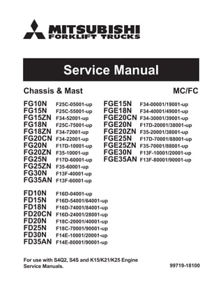
  • 1. 99719-18100 For use with S4Q2, S4S and K15/K21/K25 Engine Service Manuals. FG10N F25C-05001-up FG15N F25C-55001-up FG15ZN F34-52001-up FG18N F25C-75001-up FG18ZN F34-72001-up FG20CN F34-22001-up FG20N F17D-10001-up FG20ZN F35-10001-up FG25N F17D-60001-up FG25ZN F35-60001-up FG30N F13F-40001-up FG35AN F13F-60001-up FD10N F16D-04001-up FD15N F16D-54001/64001-up FD18N F16D-74001/84001-up FD20CN F16D-24001/28001-up FD20N F18C-20001/40001-up FD25N F18C-70001/90001-up FD30N F14E-10001/20001-up FD35AN F14E-80001/90001-up FGE15N F34-00001/19001-up FGE18N F34-40001/49001-up FGE20CN F34-30001/39001-up FGE20N F17D-20001/38001-up FGE20ZN F35-20001/38001-up FGE25N F17D-70001/88001-up FGE25ZN F35-70001/88001-up FGE30N F13F-10001/20001-up FGE35AN F13F-80001/90001-up Chassis & Mast MC/FC Service Manual
  • 2. 1 Pub. No. 99719-18100 FOREWORD This service manual is a guide for servicing Mitsubishi forklift trucks. For your convenience the instructions are grouped by systems as a ready reference. The long productive life of your lift truck(s) depends on regular and proper servicing. Servicing consistent with what you will learn by reading this service manual. Read the respective sections of this manual carefully and familiarize yourself with all of the components before attempting to start a test, repair or rebuild job. The descriptions, illustrations and specifications contained in this manual are for trucks with serial numbers in effect at the time of printing. Mitsubishi Forklift Trucks reserves the right to change specifications or designs without notice and without incurring obligations. The trucks listed in this manual are powered by K15, K21 or K25 gasoline engines or S4Q2/S4S diesel engines. For engine servicing, please refer to the applicable engine service manual. K15, K21 or K25 Gasoline engine S4Q2, S4S Diesel engine <Safety Related Signs> Indicates a specific potential hazard resulting in serious bodily injury or death. Indicates a potentially hazardous situation which, if not avoided, may result in death or serious injury or damage to the machine. Indicates a condition that can cause damage to, or shorten service life of, the machine. WARNING CAUTION NOTE
  • 3. 3 SAFETY The proper and safe lubrication and maintenance for these lift trucks, recommended by Mitsubishi Forklift Trucks, are outlined in the OPERATION & MAINTENANCE MANUAL. Read and understand the OPERATION & MAINTE- NANCE MANUAL before performing any lubrica- tion or maintenance on these trucks. Improper performance of lubrication or mainte- nance procedures is dangerous and could result in injury or death. The serviceman or mechanic may be unfamiliar with many of the systems on this truck. This makes it important to use caution when performing service work. A knowledge of the system and/or components is important before the removal or disassembly of any component. Because of the size of some of the truck components, the serviceman or mechanic should check the weights noted in this Manual. Use proper lifting procedures when removing any components. Following is a list of basic precautions that should always be observed. (1) Read and understand all warning plates and decals on the truck before operating, lubricating or repairing the product. (2) Always wear protective glasses and protective shoes when working around trucks. In particular, wear protective glasses when pounding on any part of the truck or its attachments with a hammer or sledge. Use welders gloves, hood/goggles, apron and other protective clothing appropriate to the welding job being performed. Do not wear loose fitting or torn clothing. Remove all rings from fingers when working on machinery. (3) Do not work on any truck that is supported only by lift jacks or a hoist. Always use blocks or jack stands to support the truck before performing any disassembly. (4) Lower the forks or other implements to the ground before performing any work on the truck. If this cannot be done, make sure the forks or other implements are blocked correctly to prevent them from dropping unexpectedly. Do not operate these trucks unless you have read and understood the instructions in the OPERA- TION & MAINTENANCE MANUAL. Improper truck operation is dangerous and could result in injury or death. (5) Use steps and grab handles (if applicable) when mounting or dismounting a truck. Clean any mud or debris from steps, walkways or work platforms before using. Always face truck when using steps, ladders and walkways. When it is not possible to use the designed access system, provide ladders, scaffolds, or work platforms to perform safe repair operations. (6) To avoid back injury, use a hoist when lifting com- ponents which weigh 23 kg or more. Make sure all chains, hooks, slings, etc., are in good condition and are of the correct capacity. Be sure hooks are positioned correctly. Lifting eyes are not to be side loaded during a lifting operation. (7) To avoid burns, be alert for hot parts on trucks which have just been stopped and hot fluids in lines, tubes and compartments. (8) Be careful when removing cover plates. Gradually back off the last two bolts or nuts located at oppo- site ends of the cover or device and pry cover loose to relieve any spring or other pressure, before removing the last two bolts or nuts com- pletely. (9) Be careful when removing filler caps, breathers and plugs on the truck. Hold a rag over the cap or plug to prevent being sprayed or splashed by liq- uids under pressure. The danger is even greater if the truck has just been stopped because fluids can be hot. (10)Always use tools that are in good condition and be sure you understand how to use them before performing any service work. (11)Reinstall all fasteners with same part number. Do not use a lesser quality fastener if replacements are necessary. (12)If possible, make all repairs with the truck parked on a level, hard surface. Block truck so it does not roll while working on or under truck. WARNING WARNING
  • 4. 4 (13)Disconnect battery and discharge any capacitors (electric trucks) before starting to work on truck. Hang “Do not Operate” tag in the Operator’s Com- partment. (14)Repairs, which require welding, should be per- formed only with the benefit of the appropriate ref- erence information and by personnel adequately trained and knowledgeable in welding proce- dures. Determine type of metal being welded and select correct welding procedure and electrodes, rods or wire to provide a weld metal strength equivalent at least to that of parent metal. (15)Do not damage wiring during removal operations. Reinstall the wiring so it is not damaged nor will it be damaged in operation by contacting sharp cor- ners, or by rubbing against some object or hot surface. Place wiring away from oil pipe. (16)Be sure all protective devices including guards and shields are properly installed and functioning correctly before starting a repair. If a guard or shield must be removed to perform the repair work, use extra caution. (17)Always support the mast and carriage to keep carriage or attachments raised when maintenance or repair work is performed, which requires the mast in the raised position. (18)Loose or damaged fuel, lubricant and hydraulic lines, tubes and hoses could cause fires. Do not bend or strike high pressure lines or install ones which have been bent or damaged. Inspect lines, tubes and hoses carefully. Do not check for leaks with your hands. Pin hole (very small) leaks could result in a high velocity oil stream that will be invis- ible close to the hose. This oil could penetrate the skin and cause personal injury. Use cardboard or paper to locate pin hole leaks. (19)Tighten connections to the correct torque. Make sure that all heat shields, clamps and guards are installed correctly to avoid excessive heat, vibra- tion or rubbing against other parts during opera- tion. Shields that protect against oil spray onto hot exhaust components in event of a line, tube or seal failure, must be installed correctly. (20)Relieve all pressure in air, oil or water systems before any lines, fittings or related items are dis- connected or removed. Always make sure all raised components are blocked correctly and be alert for possible pressure when disconnecting any device from a system that utilizes pressure. (21)Do not operate a truck if any rotating part is dam- aged or contacts any other part during operation. Any high speed rotating component that has been damaged or altered should be checked for bal- ance before reusing.
  • 5. 5 HOW TO USE THIS MANUAL Lift truck models covered in this manual MC Truck (Mechanical Control System) Mechanically controlled hydraulic system (conventional lever system) FC Truck (Finger-tip Control System) Electronically controlled hydraulic system Gasoline-Engine Trucks (FGE, FG)....... Trucks Equipped with K21 or K25 Gasoline Engine Diesel-Engine Trucks (FD).................... Trucks Equipped with K21 or K25 Diesel Engine Powershift Trucks................................... Trucks Equipped with Powershift Transmission Manual Transmission Trucks................. Trucks Equipped with Manual Transmission (2 Types of Clutch; Dry and Wet) 213443 MC Truck FC Truck Lever Control valve FC lever box VCM Controller Electric wiring Electromagnetic control valve Flow regulator valve Output unit Input unit
  • 6. 6 HOW TO USE THIS MANUAL (continued) (Removal, Installation, Assembly and Disassembly) Disassembly diagram (example) Suggestions for Disassembly Output shaft, Removing Remove output shaft using a special tool. A: Standard value B: Repair or Service Limit 1 2 213445 Sequence 1 Cover, Bolt, Washer (part name) 2 Snap ring (part name) 213446 Service Data Gear Backlash A 0.11 to 0.28 mm B 0.5 mm
  • 7. 7 Symbols and abbreviations Units (1) SI Units are used in this manual. (2) The following table shows the conversion of SI unit and customary unit. OP Option R1/4 Taper pipe thread (external) 1/4 inch (formerly PT1/4) RC1/8 Taper pipe thread (external) 1/4 inch (formerly PT1/8) G1/4A Straight pipe thread (external) 1/4 inch (formerly PF1/4-A) Rp1/8 Straight pipe thread (internal) 1/8 inch (formerly PS1/8) Item SI unit Customary unit Force 1 N 0.102 kgf 1 lbf 0.4536 kgf Pressure 1 kPa 0.0102 kgf/cm2 1 psi 0.0703 kgf/cm2 Torque 1 N·m 0.102 kgf·m 1 lbf·ft 0.1383 kgf·m
  • 8. CHAPTER INDEX CHAPTER INDEX CHAPTER INDEX Items GENERAL INFOMATION Truck Models Covered, Serial Number Locations, Dimensions, Technical Data COOLING SYSTEM Fan Belt Removal and Installation, Fan Belt Tension ELECTRICAL SYSTEM Console Box, Chassis Electrical Devices, Battery Maintenance, Electrical Schematic CONTROLLERS Main Functions of Controller, Input/Output Monitor, Error Codes and Troubleshooting POWER TRAIN Removal and Installation of Power Line CLUTCHES Dry-Type Clutch, Wet-Type Clutch MANUAL TRANSMISSION Structure, Removal and Installation of Transmission POWERSHIFT TRANSMISSION Torque Converter, Singe Speed Powershift Transmission Control Valve, Automatic Two-Speed Transmission FRONT AXLE AND REDUCTION DIFFERENTIAL Front Tire, Front Axle, Reduction, Differential REAR AXLE Rear Axle, Rear Tire BRAKE SYSTEM Master Cylinder, Wheel Brake, Brake Booster STEERING SYSTEM Steering Gear, Power Cylinder, Flow Divider HYDRAULIC SYSTEM Tank, Pump, Control Valve, Lift and Tilt Cylinders, Flow Regulator Valve, Down Safety Valve MAST AND FORKS Simplex and Duplex Masts, Triplex Mast SERVICE DATA Maintenance Standard, Maintenance Schedule, Periodic Replacement Parts, Lubrication Instruction, Special Tool Needed 1 2 3 4 5 6 7 8 9 10 11 12 13 14 15
  • 9. 1 Chapter 1 GENERAL INFORMATION 1. Model View............................................................................................... 1-1 2. Truck Models Covered............................................................................ 1-2 3. Serial Number Locations........................................................................ 1-3 4. Dimensions.............................................................................................. 1-4 5. Technical Data......................................................................................... 1-5 6. Performance ............................................................................................ 1-7
  • 10. 1-1 GENERAL INFORMATION Chapter 1 GENERAL INFORMATION 1. Model View 213447 MC truck 213448 FC truck
  • 11. 1-2 GENERAL INFORMATION 2. Truck Models Covered This Service Manual provides servicing and maintenance information for the following trucks: (FC type is used in torque converter model only.) Note: Characters at the end of truck model should be read as follows: (F) : FC Truck None : MC Truck Z : High-power engine model C : Short wheel base model Engine mounted Gasoline-engine truck Dual fuel gasoline/ LPG-engine truck Diesel-engine truck Non-electric controlled MC / FC MC / FC MC / FC Electric controlled MC / FC MC / FC - Truck type Electric controlled gasoline engine, Electric controlled dual fuel gasoline/ LPG engine models Non-electric controlled diesel engine models Non-electric controlled gasoline engine, Non-electric controlled dual fuel gasoline/ LPG engine models Truck model Serial number Engine mounted Truck model Serial number Engine mounted 1 ton class FG10N F25C-05001 to K15 FD10N F16D-04001 to S4Q2 FG15N F25C-55001 to K15 FD15N F16D-54001 to S4Q2 FG15ZN F34-52001 to K21 FD15N(F) F16D-64001 to S4Q2 FGE15N F34-00001 to K21E FD18N F16D-74001 to S4Q2 FGE15N(F) F34-19001 to K21E FD18N(F) F16D-84001 to S4Q2 FG18N F25C-75001 to K15 FD20CN F16D-24001 to S4Q2 FG18ZN F34-72001 to K21 FD20CN(F) F16D-28001 to S4Q2 FGE18N F34-40001 to K21E - - - FGE18N(F) F34-49001 to K21E - - - FG20CN F34-22001 to K25 - - - FGE20CN F34-30001 to K25E - - - FGE20CN(F) F34-39001 to K25E - - - 2 ton class FG20N F17D-10001 to K21 FD20N F18C-20001 to S4S FG20ZN F35-10001 to K25 FD20N(F) F18C-40001 to S4S FGE20N F17D-20001 to K21E FD25N F18C-70001 to S4S FGE20N(F) F17D-38001 to K21E FD25N(F) F18C-90001 to S4S FGE20ZN F35-20001 to K25E - - - FGE20ZN(F) F35-38001 to K25E - - - FG25N F17D-60001 to K21 - - - FG25ZN F35-60001 to K25 - - - FGE25N F17D-70001 to K21E - - - FGE25N(F) F17D-88001 to K21E - - - FGE25ZN F35-70001 to K25E - - - FGE25ZN(F) F35-88001 to K25E - - - 3 ton class FG30N F13F-40001 to K25 FD30N F14E-10001 to S4S FGE30N F13F-10001 to K25E FD30N(F) F14E-20001 to S4S FGE30N(F) F13F-20001 to K25E FD35AN F14E-80001 to S4S FG35AN F13F-60001 to K25 FD35AN(F) F14E-90001 to S4S FGE35AN F13F-80001 to K25E - - - FGE35AN(F) F13F-90001 to K25E - - -
  • 12. 1-3 GENERAL INFORMATION 3. Serial Number Locations 213449 Chassis Serial NumberName Plate Gasoline Engine Serial Number Diesel Engine Serial Number (2, 3 ton classes) Diesel Engine Serial Number (1 ton class and FD20N–25N) Transmission Serial Number (Powershift Transmission Truck) Transmission Serial Number (Manual Transmission Truck) Mast Serial Number
  • 14. 1-5 GENERAL INFORMATION 5. Technical Data Unit: mm Truck model class 1 ton class Gasoline- engine truck FG10N FG15N FG18N FG20CN FGE15N FGE18N FGE20CN FG15ZN FG18ZN Diesel-engine truck FD10N FD15N FD18N FD20CN A Maximum lift 3000 3000 3000 3000 B Free lift height 115 115 115 120 C Fork spread 200 to 920 200 to 920 200 to 920 220 to 920 D Fork length 770 920 920 920 E Tilt angle (forward – backward) 6-12 6-12 6-12 6-12 F Overall length 2980 3180 3220 3280 G Overall width (outside-to- outside of tires) Single 1065 1065 1065 1065 Double 1330 1330 1330 - H Overall height (with mast lowered) 1990 1990 1990 1990 I Height of the overhead guard 2065 2065 2065 2065 J Overall height (with mast extended) 4055 4055 4055 4055 K Tread (front wheel) Single 890 890 890 890 Double 1025 1025 1025 - L Tread (rear wheel) 900 900 900 900 M Wheel base 1400 1400 1400 1400 N Front overhang 400 400 400 415 O Minimum turning radius 1910 1950 1980 2020 P Under clearance (at center of frame) 150 150 150 150
  • 15. 1-6 GENERAL INFORMATION Unit: mm Truck model class 2 ton class 3 ton class Gasoline- engine truck FG20N FG25N FG30N FG35AN FGE20N FGE25N FGE30N FGE35AN FG20ZN FG25ZN FGE20ZN FGE25ZN Diesel-engine truck FD20N FD25N FD30N FD35AN A Maximum lift 3000 3000 3000 3000 B Free lift height 140 145 145 145 C Fork spread 220 to 1000 220 to 1000 250 to 1000 250 to 1000 D Fork length 920 920 1070 1070 E Tilt angle (forward – backward) 6-12 6-12 6-12 6-12 F Overall length 3410 3625 3795 3860 G Overall width (outside-to- outside of tires) Single 1150 1150 1275 1290 Double 1480 1480 1490 1490 H Overall height (with mast lowered) 1990 1990 2015 2130 I Height of the overhead guard 2074 2074 2093 2103 J Overall height (with mast extended) 4055 4055 4055 4055 K Tread (front wheel) Single 960 960 1060 1060 Double 1140 1140 1140 1140 L Tread (rear wheel) 980 980 980 980 M Wheel base 1600 1600 1700 1700 N Front overhang 455 460 495 495 O Minimum turning radius 2200 2230 2380 2440 P Under clearance (at center of frame) 160 160 190 200
  • 16. 1-7 GENERAL INFORMATION 6. Performance Truck model class 1 ton class Gasoline- engine truck FG10N FG15N FG18N FG20CN FGE15N FGE18N FGE20CN FG15ZN FG18ZN Diesel-engine truck FD10N FD15N FD18N FD20CN Capacity kg 1000 1500 1750 2000 Load center mm 500 500 500 500 Lift speed Loaded mm/s 490 (FG10N) 490 (FG15N) 630 (FGE15N) 570 (FG15ZN) 490 (FG18N) 630 (FGE18N) 570 (FG18ZN) 570 (FG20CN) 630 (FGE20CN) 630 (FD10N) 630 (FD15N) 630 (FD18N) 630 (FD20CN) Unloaded mm/s 560 (FG10N) 560 (FG15N) 650 (FGE15N) 650 (FG15ZN) 560 (FG18N) 650 (FGE18N) 650 (FG18ZN) 650 (FG20CN) 650 (FGE20CN) 690 (FD10N) 690 (FD15N) 690 (FD18N) 690 (FD20CN) Travel speed (Powershift Truck) Loaded km/h 19.0 19.0 19.0 19.0 Unloaded km/h 19.5 19.5 19.5 19.5
  • 17. 1-8 GENERAL INFORMATION Truck model class 2 ton class 3 ton class Gasoline- engine truck FG20N FG25N FG30N FG35AN FGE20N FGE25N FGE30N FGE35AN FG20ZN FG25ZN FGE20ZN FGE25ZN Diesel-engine truck FD20N FD25N FD30N FD35AN Capacity kg 2000 2500 3000 3500 Load center mm 500 500 500 500 Lift speed Loaded mm/s 520 (FG20N) 580 (FGE20N) 580 (FG20ZN) 640 (FGE20ZN) 520 (FG25N) 580 (FGE25N) 580 (FG25ZN) 640 (FGE25ZN) 460 (FG30N) 510 (FGE30N) 390 (FG35AN) 430 (FGE35AN) 630 (FD20N) 630 (FD25N) 500 (FD30N) 420 (FD35AN) Unloaded mm/s 600 (FG20N) 590 (FGE20N) 660 (FG20ZN) 660 (FGE20ZN) 600 (FG25N) 590 (FGE25N) 660 (FG25ZN) 660 (FGE25ZN) 530 (FG30N) 530 (FGE30N) 450 (FG35AN) 440 (FGE35AN) 660 (FD20N) 660 (FD25N) 530 (FD30N) 450 (FD35AN) Travel speed (Powershift Truck) Loaded km/h 19.0 19.0 19.0 19.0 Unloaded km/h 19.5 19.5 19.5 19.5
  • 18. 2 Chapter 2 COOLING SYSTEM 1. Specifications.......................................................................................... 2-1 2. Structure .................................................................................................. 2-2 3. Removal and Installation........................................................................ 2-3 3.1 Fan Belt Removal....................................................................................................2-3 3.2 Suggestions for Removal ........................................................................................2-3 3.3 Installation ...............................................................................................................2-4 4. Inspection and Adjustment.................................................................... 2-5 4.1 Fan Belt Inspection..................................................................................................2-5 4.2 Fan Belt Tension .....................................................................................................2-5 4.3 Connecting Hoses ...................................................................................................2-5 4.4 Unit Layout ..............................................................................................................2-6 4.5 Coolant ....................................................................................................................2-6 4.6 Radiator Cap ...........................................................................................................2-6
  • 19. 2-1 COOLING SYSTEM Chapter 2 COOLING SYSTEM 1. Specifications Items Truck type 1 ton class 2 ton class 3 ton class Cooling system Cooling method Water-cooled, forced circulation Radiator Corrugated fin (pressure) type Water pump Centrifugal type Thermostat Wax pellet type
  • 20. 2-2 COOLING SYSTEM 2. Structure 213451 S4Q2 S4S Hose layout S4Q2 engine K15, K21, K25 engines S4S engine Lower hose Shroud Upper hose Radiator Reservoir tank K15, K21, K25 Fan (directly coupled to engine)
  • 21. 2-3 COOLING SYSTEM 3. Removal and Installation 3.1 Fan Belt Removal 3.2 Suggestions for Removal (1) Loosen the tension pulley lock bolt by three or four turns. If the bolt is loosened insufficiently, the tension pulley will not move. Note: Do not loosen the lock bolt to such an extent that the bolt would be removed. (2) Move the tension pulley fully toward the fan, then remove the belt. 1 Tension pulley assembly, bolt 2 Belt 213452 Engine Fan 21 213453 Tension pulley Fan
  • 22. 2-4 COOLING SYSTEM 3.3 Installation To install, follow the removal sequence in reverse. Also follow the instructions given below. (1) Before installing the belt, turn the fan to check for smooth rotation. Replace the bearing if it gener- ates abnormal sound. (2) After installing the belt, push it to make sure that the tension pulley moves, then tighten the pulley lock bolt firmly.
  • 23. 2-5 COOLING SYSTEM 4. Inspection and Adjustment 4.1 Fan Belt Inspection (1) Check the belt for contamination from oil, grease or dust. Replace the belt if required. When the contamination is slight, clean the belt with a rag or paper towel. Do not use gasoline, oil or any other solvent to clean the belt. (2) During the engine overhaul or belt tension adjust- ment, check the condition of the belt. Replace the belt if it has any damage. 4.2 Fan Belt Tension Apply a force of 98 N (10 kgf) perpendicularly to the belt at a point midway between the fan pulley and ten- sion pulley. Adjust the belt tension between 11 to 13 mm. 4.3 Connecting Hoses When connecting the hoses to the radiator, fit their ends fully on the fittings and secure them with clamps. Make sure that each hose is correctly connected and over the flare of the fitting. 213454 Tension pulley Fan pulley 213455 Hose
  • 24. 2-6 COOLING SYSTEM 4.4 Unit Layout 4.5 Coolant Fill the radiator with coolant containing antifreeze. After starting the engine and letting it warm up during operation, check for abnormal noises. Check the cool- ant level in the reserve tank to ensure it meets the specification. 4.6 Radiator Cap 213456 Coolant quantity Item Truck type 1 ton class 2 ton class 3 ton class Reservoir tank (FULL level) L 0.65 0.65 0.65 Total quantity of coolant (including coolant in hoses) L 6.8 7.4 8.7 Opening pressure 88±14.7 kPa Vacuum valve 0 to 4.9 kPa
  • 25. 3 Chapter 3 ELECTRIC SYSTEM 1. Chassis Electrical Devices Wiring Outline ........................................... 3-1 1.1 (One) .......................................................................................................................3-1 1.2 (Two) .......................................................................................................................3-2 2. Structure .................................................................................................. 3-3 2.1 Console Box ............................................................................................................3-3 2.2 Major Electrical Components...................................................................................3-5 2.3 Table of Lamps......................................................................................................3-15 3. Console Box .......................................................................................... 3-16 3.1 Disassembly ..........................................................................................................3-16 4. Battery Maintenance............................................................................. 3-17 4.1 State of Charge and Electrolyte Specific Gravity (S.G.) Adjustment.....................3-17 4.2 Specific Gravity Reading and State of Charge......................................................3-17 4.3 Charging Precautions............................................................................................3-17 5. Instrument Panel................................................................................... 3-18 5.1 Instrument Panel Screen Element.........................................................................3-18 5.2 Basic Screen Display.............................................................................................3-19 5.3 Basic Operation.....................................................................................................3-22 5.4 When an Error Occurs...........................................................................................3-28 5.5 Warning Lamps .....................................................................................................3-30 5.6 Optional Functions.................................................................................................3-31 5.7 Hour Meters...........................................................................................................3-38 5.8 Troubleshooting.....................................................................................................3-40 6. Wire Color.............................................................................................. 3-41 6.1 List of Wire Colors .................................................................................................3-41 7. Troubleshooting.................................................................................... 3-42 7.1 Starter System.......................................................................................................3-42 7.2 Gauges..................................................................................................................3-42 7.3 Lighting System.....................................................................................................3-43 8. Electrical Schematic ............................................................................. 3-45
  • 26. 3-1 ELECTRIC SYSTEM Chapter 3 ELECTRIC SYSTEM 1. Chassis Electrical Devices Wiring Outline 1.1 (One) 213457 Harness, front combination Harness, front combination Main harness Harness, rear combination
  • 27. 3-2 ELECTRIC SYSTEM 1.2 (Two) 213458 Clip VCM(Vehicle control module) ECM (Gasoline engine control module) DCM (Diesel engine control module) Key Starter switch Transmission Back buzzer Harness, rear combination Battery seat Fuse box, Fuse Harness, front combination Relay box, RelayVehicle speed sensor (Pulse generator) Horn GLE Connector Connector bracket GSE Connector Harness, front combination Main harness Warning buzzer Select switch Output unit Input unit QGS Controller
  • 28. 3-3 ELECTRIC SYSTEM 2. Structure 2.1 Console Box 1 Water temperature gauge 2 Fuel gauge 3 Hour meter, various warning lights 4 Instrument panel 5 Starter switch 6 Lighting switch, turn signal switch 7 Forward-reverse lever 214140 N 2 4 3 1 6 7 5
  • 29. 3-4 ELECTRIC SYSTEM 2.1.1 Function of Instrument Panel Description of function Inspection method of blown bulbs for instrument panel All warning and indicator lamps are normal, if they glow, when the starter switch is turned to the I (ON) position. Ref. No. Name of indicators and warning lamps When turned off When glows or blinks Remark A Parking brake warning lamp Normal When parking brake is applied (glows) - B Seat belt warning lamp Fastened When seat belt is not fastened (glows) - C Charge warning lamp Normal charging When charging is not normal (glows / When engine is not run- ning always glows) - D Multi-purpose warning lamp Normal When a minor failure occurs or operating caution is being issued (glows) - E Torque converter fluid temperature warning lamp Normal temperature When torque converter fluid tem- perature is not normal (glows) - F Engine oil pressure warning lamp Normal When engine oil pressure is low (glows / When engine is not run- ning always glows) - G Engine warning lamp Normal When the engine is failed (glows) - H Glow pilot lamp Preheating completed When the grow plug is ON (glows) - I Smart shift indicator lamp - When protective function of sud- den acceleration/full reverse (shifting in the opposite direction of traveling) is activated (glows) Option J Mast interlock indicator lamp - When mast interlock is activated (glows) - K Cursor buttons - - - L Fuel gauge Indicates remaining fuel amount with key in “ON” position. - M LCD screen - - - N Water temperature gauge Indicates water temperature with key in “ON” position. - O Enter/display switch button - - - 214141 A B C D E F G H I J K L M N O
  • 30. 3-5 ELECTRIC SYSTEM 2.2 Major Electrical Components 2.2.1 Starter switch The diesel-engine truck, which uses a distributor type injection pump, is provided with an engine automatic stop mechanism of the starter switch fuel cut system. The gasoline-engine truck is also provided with an engine automatic stop mechanism of the fuel cut sys- tem. (Starter switch with Anti-Restart Lock) This starter switch has an anti-restarting function. This switch has a built-in anti-restart lock, so the key cannot be turned from (ON) to (START) position while the engine is running. This prevents starter breakage or flywheel damage caused by an operator restarting the truck when the engine is running. The gasoline- and diesel-engine models use the same starter switch. In the diesel -engine models, the l (ON) position of the switch is for energizing the glow plugs. Connection Table B MST G 213459 (OFF) (ON) (START) For gasoline truck (12V) Terminal G B M ST Key in and out OFF Yes ON (when operating) ○--------- -----------○ No START (when starting engine) ○--------- -----------○----------- -----------○ No
  • 31. 3-6 ELECTRIC SYSTEM 2.2.2 Lighting switch, turn signal switch 213460 T-3 L-2 L-4 L-5 L-3L-1 T-2 T-1 421 3 5 4 2 31 5 Light switch/ turn signal lever Front Direction lever Wheel angle sensor Light switch/ turn signal switch Horn contact Horn Wheel angle sensor connector Shift change switch (F, N, R) Forward of truck Boot Horn contact Boot Lighting switch, turn signal switch Lighting switch, turn signal switch Forward-reverse selector switch
  • 32. 3-7 ELECTRIC SYSTEM 2.2.3 Horn Check that the horn activates when applying the spec- ified voltage to both terminals of the horn T1 and T2. Replace the horn if it does not activate or its sound is abnormal. Operating voltage: DC12V (Gasoline and diesel trucks) Note:The installed position is that of an actual truck as shown in the illustration. 2.2.4 Tank Unit 213463 T1 T2 Up Down Contact Coil Vent hole 213464 3/4 1/4 Referential Standards Tolerance (ohm) E 1/4 1/2 +12 +2 3/4 F 80 49.5 32 19 10 ±3 +1.0 -0.5 E F 1/2 Fuel pump Pressure relief valve Fuel filter Float position Standard resistance value (ohm)
  • 33. 3-8 ELECTRIC SYSTEM 2.2.5 Brake fluid sensor Refer to the brake system. 2.2.6 Stop lamp switch Connect a tester across the terminals and check that the lamps turn ON and OFF when the push rod extended projection is to the specified value. Measure the insulation resistance value across the ter- minals when the push rod is pushed in. Replace the switch if the measured insulation resis- tance value is less than the value listed below. Rated voltage DC12V 213465 IndicatororON activatingposition (emergency energization) 3±2mm Insulation resistance value 1 M ohm or more (with megger tester at 500V) 213466 Push rod OFF ON M10×1.25 4 2mmmm
  • 34. 3-9 ELECTRIC SYSTEM 2.2.7 Direction lever assembly (Powershift truck) 2.2.8 Backup lamp switch (Manual T/M truck) 213467 (10)(10) Connection table G/W B B/R B L/W 1 2 3 4 5 Forward of vehicle F Forward N Neutral R Reverse F Forward N Neutral R Reverse Lever position Terminal Wire color Connector of FNR switch Connector of FNR switch 213468 (0.5 RL) ON OFF 19.5 mm 2 mm 2 mm M12×1.75 Shift rail (for forward-reverse) Backup lamp switch Transmission case
  • 35. Thank you very much for your reading. Please Click Here Then Get More Information.