2G and 3G Layer 3 Messages Overview
•Descargar como DOCX, PDF•
14 recomendaciones•13,477 vistas

layer 3

Recomendados
Más contenido relacionado
La actualidad más candente
La actualidad más candente (20)
Destacado
Destacado (13)
Similar a 2G and 3G Layer 3 Messages Overview
Similar a 2G and 3G Layer 3 Messages Overview (20)
Último
Último (20)
2G and 3G Layer 3 Messages Overview
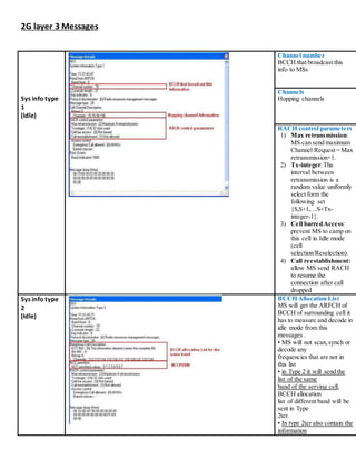
- 1. 2G layer 3 Messages Sys info type 1 (Idle) Channel number BCCH that broadcast this info to MSs Channels Hopping channels RACH control parameters 1) Max retransmission: MS can send maximum Channel Request = Max retransmission+1. 2) Tx-integer:The interval between retransmission is a random value uniformly select form the following set {S,S+1,…S+Tx- integer-1}. 3) Cell barredAccess: prevent MS to camp on this cell in Idle mode (cell selection/Reselection). 4) Call reestablishment: allow MS send RACH to resume the connection after call dropped Sys info type 2 (Idle) BCCH Allocation List MS will get the ARFCH of BCCH of surrounding cell it has to measure and decode in idle mode from this messages . • MS will not scan,synch or decode any frequencies that are not in this list • in Type 2 it will send the list of the same band of the serving cell, BCCH allocation list of different band will be sent in Type 2ter. • In type 2ter also contain the information
- 2. about how many neighbors from different band mobiles have to add in the measurement report. NCC permitted MS will use this value when it first enter to dedicated mode before it get new information on SACCH. Sys info type 3 (Idle) Cell info MCC & MNC & LAC Control channel 1) ATT IMSI attach/detach flag 2) BS-AG-BLKS-RES number of block reserve for access grant, use in the calculation of paging group. 3) CCCH-CONF indicate whether CCCH is combined with SDCCH. 4) BS-PA-MFRMS Multiframe for paging group calculation. 5) T3212 periodic registration timer. Cell Option 1) DTXindicator whether mobile shall use DTX or not. 2) RADIO-LINK- TIMEOUT the radio link timeout for DL connection that mobile will use for this cell. Cell selection parameters 1) CRH : for diff. LAC 2) MS-TXPWR : max allowed UL power 3) RXLEV-ACCESS- MIN: min allowed power in DL to access Cell reselection parameters
- 3. Sys info type 4 (Idle) Broadcast as similar information as System Information Type3 but less detail. Sys info type 5 (Dedicated) BCCH Allocation List • As same as System Information Type2 in idle mode, System Information Type5 contain the BAList which mobile have to monitor in dedicated mode. • in Type 5 it will send the list of the same band of the serving cell, BCCH allocation list of different band will be sent in Type 5ter. • In type 5ter also contain the information about how many neighbors from different band mobiles have to add in the measurement report.
- 4. Sys info type 6 (Dedicated) Cell options • PWRC indicated. • DTX indicator whether DTX is used. • Radio Link Timeout The counter of radio link failure and release the channel Radio link timeout work in following manner, when MS fail to decode SACCH block it will decrease by one, but if the SACCH block can be decode again its increment is 2. Channel request Random Access Information • Establishment cause contains the reason for requesting the establishment of the connection. • Random reference random value as a reference to the network when channel is assigned. Immediate assignment Channel Description • The details of target physical channel of SDCCH which MS have to camp on in dedicated mode. Request Reference • Include the Establishment cause and random reference value from the channel request. Timing Advance • The initial timing advance values, which BSC calculate from the delay of random access
- 5. Assignment command Description ofthe channel • Channel Type indicate the target channel (TCHF/TCHH). • TN target TCH timeslot number. • TSC training sequence code. • Hopping RF channel whether target channel is HOPPING. • MAIO start MAI for hopping. • HSN hopping sequence number. Power Command • Power level the initial power use in this connection. Mobile allocation • Mobile allocation array the frequency which will use when hopping. Cell channel description • Channels the frequency available in this cells Measurement report Serving Cell measurement • RxLev Full rxlevel of serving cell average for full set. • Rxlev Sub rxlevel of serving cell average for sub set • RxQual full rxqual of serving cell average for full set. • RxQual Sub rxqual of serving average for sub set. Six strongest neighbor • RxLev rxlevel on BCCH of neighboring cell . • BSIC BSIC of the neighbor. • BCCH-INDEXthe index of BCCH on BAList in system information type5.
- 6. H.O Command Cell Description • BCCH and BSIC of the target cell Channel Description • allocated channel at target cell, in case of Hopping it will inform MAIO and HSN Handover Reference • reference value use to identify the Handover Access from the mobile Synchronization • indicate the handover is synchronous or asynchronous. Synchronous handover case after MS send Handover Access,it will tune the transceiver to the target channel without waiting for Physical Information message H.O Access Handover Reference • Refer that this Handover Access belong to which Handover Command. Handover Access is a very short message (1 octet), which using Access Burst as same as Channel Request. In some case ,it is possible that this Handover Access will trigger the allocation of SDCCH of surrounding cells because they think it is the channel request message. This phenomena can cause the problem on immediate assignment success rate Physical Info. Timing Advance • This timing advance tell the mobile about the timing advance which will use in the target cell.
- 7. Location Updating Request Location Update Type • Indicate the type of location update LocationArea Identity • the information of current LAI stored in SIM card (old LAI). Mobile Station Classmark • contain MS capability. Mobile Identity • Identity of the MS can be either TMSI or IMSI Location Updating Accept Location Area Identity • the information of new LAI which will replace the current LAI in SIM card
- 10. 3G Layer 3 messages No. Name Direction Description 1 Measurement report UE Node B The UE sends a report to the Node B including the best detected neighbors and their RSCP and Ec/No and the scrambling code on the UL-DCCH 2 Active set update Node B UE The Node B sends this message to command the UE to add, remove or replace the active set as action in the soft handover process on the DL-DCCH. It provides the UE with the scrambling code of the cell exposed to the action (add, remove or replace) in addition to the max. UL allowed TX power as a power control command from the Node B to the UE (dedicated mode). 3 Active set update complete UE Node B This message is sent by the UE to the Node B on the UL-DCCH as an acknowledgement to the active set update command received from the Node B indicating that the action (add, remove or replace) is completed successfully. 4 Measurement control Node B UE This is a message sent on the DL-DCCH by the Node B to the UE in the dedicated mode to command the UE to send measurement report on which the Node B decide what is the SHO command to be sent 5 Disconnect Node B UE This message is an indication for disconnecting the call. 6 Release UE Node B This message is sent to release the connection between the MS and Node- B 7 Release complete Node B UE This message is a response message for the release message. 8 RRC connection release Node B UE This message is to release the RRC connection and this message. It includes authentication code and release cause. 9 RRC connection release complete UE Node B This message confirms that the RRC connection is released. 10 Cell selection UE Node B This message identifies the cell to be serving the UE at start up.
- 11. 11 Cell reselection UE Node B This message identifies the cell to be serving the UE at idle mode. 12 RRC connection request UE Node B This message is sent by the UE on the UL-CCCH to request initiating RRC transmission between the Node B and the UE. The UE sends MCC, MNC, CPICH Ec/No, establishment cause, location area code and TMSI. 13 RRC connection set up Node B UE This message is sent by the Node B to the UE on the DL-CCCH including information to help the UE to start transmission and receiving. These information as channel coding type, CRC size, SRNC identity, RNTI, power control information, rate matching attribute, scrambling code type, scrambling code, channel mapping information, radio bearer information, spreading factor, UTRAN-DRX-Cycle Length Coeff. and TFCI. 14 RRC connection set up complete UE Node B This message is sent by the UE to the Node B on the UL-DCCH as an acknowledgment to the RRC connection set up message and associated with UE capabilities and ciphering algorithm supported 15 Initial direct transfer UE Node B This message is sent on the UL-DCCH including service description and core network domain identity to facilitate routing and initiate the direct transfer between the CN and the UE and the RNC and Node B became transparent. 16 Downlink direct transfer Node B UE This message is sent in the DL including NAS information directed from the CN to the UE. 17 Uplink direct transfer UE Node B This message is sent in the UL including NAS information directed from the UE to the CN. 18 Identity request Node B UE This message is sent b y the Node B to the UE requesting the IMEI of the UE 19 Identity response UE Node B This message is sent by the UE to the Node B including the IMEI of the UE 20 Authentication request Node B UE This message is sent by the Node B to the UE including the RAND to request
- 12. authentication of the UE. 21 Authentication response UE Node B This message is sent by the UE to the Node B including the SRES after calculating it from the previous RAND sent by the network to complete the authentication process. 22 Security mode command Node B UE This message is sent on DL-DCCH. 23 Security mode complete UE Node B This message is sent on UL-DCCH. 24 Alerting UE Node B This message is sent in downlink direction in case of call originating. It is sent as constant stream of bits. In case of terminating call it is an uplink message. In both cases contains the bits indicating the sound of ringing tone. 25 Call set up UE Node B These two messages have the setup duration one of them for MOC and the other one for MTC. 26 Call established TEMS Indication 27 Connect acknowledge UE Node B This message is an acknowledgment for connection before and after the call established message. 28 Connect Node B UE It indicates establishing the call. 29 Location updating request UE Node B This message is sent for requesting location updating. It has the following parameters: MCC, MNC, LAC (old), TMSI and class- mark. 30 Location updating accept Node B UE This message that has the following parameters: MCC, MNC and LAC (new) 31 TMSI reallocation command Node B UE This message is sent on the downlink to command the UE to change the TMSI. This message is including MCC, MNC, LAC and TMSI 32 TMSI reallocation complete UE Node B This message is sent by the UE as an acknowledge to the Node B confirming the TMSI reallocation 33 Location area update TEMS Indication for Location update message. 34 RRC connection abnormal release It is an indication from TEMS.
- 13. 35 Dropped call For no service dropped call (poor coverage). It is an indication from TEMS 36 Paging type 1 Node B UE This message is sent by the Node B to one mobile in the cell including the TEMSI of the paged mobile in addition to the paging cause. 37 Paging response UE Node B This message is sent by the UE as an acknowledgment to the paging type 1 message including the UE capabilities such as: supported ciphering algorithm, LCS, frequency capabilities and mobile identity (TMSI). 38 CM service request UE Node B It contains CM service type, user equipment capabilities as: RF power capabilities, ciphering algorithm supported, Frequency Capability, Mobile identity (TMSI). 39 CM service accept Node B UE It is a message sent by Node B to acknowledge CM service request message 40 Call confirmed UE Node B It is confirmation for call setup. It contains radio bearer capabilities. 41 Radio bearer reconfiguration Node B UE This message is sent on changing the service which consequently need changing the bearer parameters. 42 Radio bearer reconfiguration complete UE Node B This message is sent on the DCCH to acknowledge the radio bearer reconfiguration message. 43 Physical channel reconfiguration Node B UE This message is sent to notify the UE to enter or leave the compressed mode. 44 Physical channel reconfiguration complete UE Node B This message is sent on the DCCH to acknowledge the physical channel reconfiguration message. 45 Radio bearer setup Node B UE It is transmitted on (DL-DCCH). It contains Radio Bearer/logical/transport channel mapping, Channel coding, Radio Link Control (RLC) parameters, TTI, Transport Format Combination Set
- 14. (TFCS), Spreading Factor (SF), Scrambling Code, power Control parameters. 46 Radio bearer Setup complete UE Node B It is transmitted on (UL-DCCH). It is acknowledge for radio bearer setup. 47 Progress Node B UE It is 48 Call proceeding Node B UE It is sent by the MSC to the MS in case of mobile originating call to inform the MS that the address information which the MS has sent to MSC in Setup message is received and processed. 49 Call attempt Indication for call attempt from TEMS. 50 Setup UE Node B It contains the MS capability (speech versions) and the called mobile number. 51 Call initiation It is an indication for call initiation from TEMS. 52 System information Node B UE It is transmitted on (BCCH – BCH) to be received by all UEs in the cell. It contains scrambling code and UARFCN of the cell and information about MIB and SIBs. 53 System information message (MIB, SC=…..) (value tag) Node B UE It is the main controlling block that the UE needs to locate. It contains either scheduling information for the SIBs directly, or scheduling information for up to two scheduling blocks which themselves define the scheduling for the SIBs. The scheduling is done by defining the number of segments of each SIB in the SFN, the repetition of this SIB and the SIB position within the System Frame Number (SFN) It contains also MNC, MCC. 54 System information message (SIB3, SC=….) (value tag) Node B UE It contains some parameters UE needs in cell selection and reselection operation as: Qrxlevmin, Qqualmin,..... 55 System information message (SIB7, SC=….)(timer) Node B UE It contains measurement of uplink interference for RACH. 56 System information message (SIB5, SC=….) (value tag) Node B UE It contains the configuration parameters of physical channels of the cell in idle mode as: S-CCPCHinformation, PRACH informationandHSDPAcell capability.
- 15. 57 System information message (SIB12, SC=….) (value tag) Node B UE It contains the parameters used in intra- frequency, inter-frequency and inter- system handovers. It is sent when the mobile is in Cell_FACH, Cell_PCH, URA_PCH, Idle mode. 58 System information message (SIB1, SC=….) (value tag) Node B UE It contains core network information as: LAC, RAC, DRX cycle length coefficient for both CS and PS and contains the timers used in events timing which is important in end to end connection to avoid unnecessary allocation of network resources. 59 System information message (SIB11, SC=….) (value tag) Node B UE It contains the neighbors list of the serving cell and all the parameters for each neighbor used in intra-frequency, inter-frequency and inter-system handovers. 60 Inter-frequency cell reselection This message is sent when frequency changes. It includes the new cell scrambling code and the UARFCN.