
Recomendados
Más contenido relacionado
La actualidad más candente
La actualidad más candente (20)
Similar a Various Load Cases In Pipe Stress Analysis
Similar a Various Load Cases In Pipe Stress Analysis (20)
Último
Último (20)
Various Load Cases In Pipe Stress Analysis
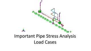
- 1. Important Pipe Stress Analysis Load Cases
- 2. What is Pipe Stress Analysis ? Analysis carried out on any piping design project to ensure structural and operatonal integrity and optmal design. Predicts stresses in piping and loads on equipment resultng rom various actors like pressure, temperature, weight, seismic and other related actors. An important actor in detailed piping engineering to ensure that the piping system doesn’t ail under any sort o stresses and loads. Governed by diferent codes and standards that speci y minimum requirements or sa e design and constructon. Pipe Stress Analysis o Multple Heaters – A Success ul Project By Rishabh Engineering
- 3. Why Pipe Stress Analysis? Any piping system is subjected to diferent kinds o loads during their design li e cycle. These loads result in the development o stresses in the piping system. To analyze and measure these stresses, pipe stress analysis is carried out. Pipe stress engineers use reliable sofware like CAESAR II to analyze stress in these systems and check whether they are under permissible limits as defned by codes and standards. Pipe Stress Analysis o Gas Metering System by rishabheng.com
- 4. Loads Considered During Pipe Stress Analysis Diferent types o loads considered during piping stress analysis Thermal Loads at Various Operatng Conditons Sustained Loads Seismic Loads Wind Loads PSV Reacton Force Slug Force Pipe Stress Analysis o Horizontal Heater by www.rishabheng.com
- 5. Thermal Loads At Various Operatng Conditons Pipes contract or expand due to the temperature change which results in thermal load To avoid ailure due to thermal load, the piping system must be made fexible Piping system must be analyzed or the design temperature and operatng temperature I design temperature o pipes > 80 deg C and diference between operatng and design temperature > 25 deg C, then the maximum/minimum operatng temperatures, as derived rom Process Group, can be used in pipe stress analysis instead o design temperature.
- 6. Sustained Loads “Allowable stresses or sustained loads” have been set by internatonal piping codes or the axial stresses caused by dead-weight and pressure to avoid ailure. To achieve it, the piping system is required to be supported vertcally. These are the loads that exist throughout the plant operaton. Consists o loads due to internal pressure & dead-weight. Dead-weights are to be considered as ollows Design pressure Weight o Pipe and associated components such as Flanges, Valves, Strainer, Sight glass etc., mounted on the Piping System. Weight o Fluid/contents in the piping Insulaton and cladding weight Hydro test loads, i applicable Snow load, i applicable
- 7. Seismic Loads These are considered or piping system to be implemented in seismic zone. Statc seismic analysis needs to be carried out to evaluate seismic stresses, displacements and loads. Seismic coefcient to be provided by client. I not provided then, statc seismic coefcient is calculated using relevant codes in terms o ‘g’ – as per project specifc in ormaton. To be considered to be actng along the horizontal axes – along North, South, East, and West directons but not actng at the same tme.
- 8. Occasional Loads Loads imposed due to occasional events like wind, earthquake, etc. Wind loads - considered or lines with external diameter 14” NB (including insulatonn or above and at elevaton 10 meters or higher rom the ground level. Lateral supports are atached to protect piping rom wind efects In case o earthquakes, some restng supports are constructed as integral two way lateral and vertcal restraints. Normal operatng temperature is used when analyzing occasional loads. Two concurrent occasional loads shouldn’t be considered in stress analysis.
- 9. PSV Reacton Force I the piping system uses pressure sa ety valves (PSVn, then reacton orce due to PSV operaton is applicable. Dynamic Load Factor (DLFn o 2.0 must be applied on valve reacton orce value. For high reacton orce value, DLF calculated as per appendix-II o ASME B31.1 should be used.
- 10. Slug Force Considered when stress analysis or lines have slug fow regime. It is calculated as ollows: Fslug = (ρn (An (V2n [2(1 – cos θn]1/2 DLF Where, Fslug = Force due to slug in Newton. ρ = Density o the slug in Kg/m3 A = Inside area o pipe cross secton in m2, V = Velocity o moving slug in m/sec. θ = inclusion angle at elbow or change o directon DLF = Dynamic Load Factor (DLFn equal to two shall be used, unless more accurate value is available. Faxial = (ρn (An (V2n DLF Forthogonal = (ρn (An (V2n DLF Slug propertes can be obtained rom Process group.
- 11. Conclusion All the types o load cases must be considered or stress analysis o any piping system. Ignoring any one o them could result in the piping system ailure. In spite o the best design tools and sophistcated sofware, any pipe stress analysis project is not complete without clever engineering judgment, experience and oresight.
- 12. Thank You Contact Us: USA Ofce: Rishabh Engineering Services Inc. 2690 S. White Road, Ste. 245, San Jose, CA 95148, USA US TollFree: +1-877-RISHABH (+1-877-747-4224n US Phone: +1-201-484-7302 UK Ofce: 4th foor, Scotsh Provident House, 76 – 80 College Road, Harrow, HA1 1BQ, U.K. UK Phone: +44-207-993-8162 India Ofce: Plot 66, Beside Sigil India, Padra Road, Atladra, Vadodara 390012, Gujarat, India India Phone(sn: +91-8511122697 +91-265-2680159 +91-265-2681159 Email: sales@rishabheng.com Website: htp://www.rishabheng.comFollow Us: