Cnc lathe
•Descargar como PPT, PDF•
18 recomendaciones•4,823 vistas

OPERATION ON LATHE BY CNC CODS.

Recomendados
Más contenido relacionado
La actualidad más candente
La actualidad más candente (20)
Destacado
Destacado (16)
Similar a Cnc lathe
Similar a Cnc lathe (20)
Más de kailashgavare
Más de kailashgavare (7)
Último
Último (20)
Cnc lathe
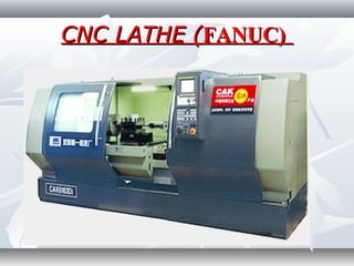
- 1. CNC LATHE (CNC LATHE (FANUC)FANUC)
- 2. Part Programming GeometryPart Programming Geometry Co-ordinate System for a CNC LatheCo-ordinate System for a CNC Lathe
- 3. Machine Zero point (M)Machine Zero point (M)
- 4. Workpiece Zero Point (W)Workpiece Zero Point (W)
- 5. Reference Point (R)Reference Point (R)
- 6. CNC LATHE (CNC LATHE (MTAB)MTAB) Program build-up for CNC Lathe using FANUCProgram build-up for CNC Lathe using FANUC System.System. CNC Program can be divided into three parts.CNC Program can be divided into three parts. 1. Start-up Program1. Start-up Program 2. Profile Program2. Profile Program 3. End of the Program3. End of the Program
- 7. 1. Start-up Program1. Start-up Program O1000O1000 G21 G98G21 G98 G28 U0 W0G28 U0 W0 M06 T1M06 T1 M03 S1500M03 S1500 G00 X32G00 X32 Z5Z5
- 8. Explanation: O1000:- While writing a program on FANUC controller first line has to be started with letter “O” followed by four digit number which specifies the program number. G21 G98:- G21 - specifies that program is done in metric units G98 gives the unit of feed in mm / min G28 U0 W0:- Makes the tool to go to home position. U & W are secondary movements about x and z axis. M06 T1:- Tool Change with tool position No: 1 M03 S1500:- Makes the spindle rotation in clockwise with spindle rotates at 1500 RPM G00 X32 Z5:- G00 gives rapid position of the tool to a point X32 Z5. This is just above the billet. This point is called as the Tool entry Point.
- 9. 2. Profile Program:2. Profile Program: Profile program is based on the given part drawing.Profile program is based on the given part drawing.
- 10. 3. End of the Program3. End of the Program G28 U0 W0G28 U0 W0 M05M05 M30M30 G28 U0 W0G28 U0 W0:-:- Makes the tool to go to home position. U & W areMakes the tool to go to home position. U & W are secondarysecondary Movements about X and Z axis.Movements about X and Z axis. M05M05 :-:- Stop the SpindleStop the Spindle M30M30:- program stop:- program stop
- 11. *Miscellaneous Function*Miscellaneous Function ((M Codes)M Codes) M00M00--Program StopProgram Stop M01M01--Optional StopOptional Stop M02M02--Program EndProgram End M03M03--Spindle Rotation ClockwiseSpindle Rotation Clockwise M04M04--Spindle Rotation Counter ClockwiseSpindle Rotation Counter Clockwise M05M05--Spindle StopSpindle Stop M06M06--Tool ChangeTool Change M08M08--Coolant OnCoolant On M09M09--Coolant OffCoolant Off M10M10--Chuck OpenChuck Open M11M11--Chuck CloseChuck Close M30M30--Program Stop and RewindProgram Stop and Rewind
- 12. Miscellaneous Function (M Codes)Miscellaneous Function (M Codes) M62M62--Output 1 OnOutput 1 On M63M63--Output 2 OnOutput 2 On M64M64--Output 1 OffOutput 1 Off M65M65--Output 2 OffOutput 2 Off M66M66--Wait input 1 OnWait input 1 On M67M67--Wait input 2 OnWait input 2 On M76M76--Wait input 1 OffWait input 1 Off M77M77--Wait input 2 OffWait input 2 Off M98M98--Sub-program CallSub-program Call M99M99--Sub-program ExitSub-program Exit
- 13. G-CodesG-Codes G00 Rapid Motion PositioningG00 Rapid Motion Positioning G01 Linear Interpolation MotionG01 Linear Interpolation Motion G02 CW Circular Interpolation Motion / G03 CCW CircularG02 CW Circular Interpolation Motion / G03 CCW Circular Interpolation MotionInterpolation Motion G04 DwellG04 Dwell G10 Set OffsetsG10 Set Offsets G17 XY Plane, G18 ZX Plane and G19 YZ PlaneG17 XY Plane, G18 ZX Plane and G19 YZ Plane G18 ZX Plane SelectionG18 ZX Plane Selection G18 ZX Plane SelectionG18 ZX Plane Selection G20 Select Inches / G21 Select MetricG20 Select Inches / G21 Select Metric
- 14. G-CodesG-Codes G28 Return To Machine Zero, set optional G29 ReferenceG28 Return To Machine Zero, set optional G29 Reference pointpoint G40 Tool Nose Compensation CancelG40 Tool Nose Compensation Cancel G41 Tool Nose Compensation Left / G42 TNC RightG41 Tool Nose Compensation Left / G42 TNC Right G70 Finishing CycleG70 Finishing Cycle G71 O.D./I.D. Stock Removal CycleG71 O.D./I.D. Stock Removal Cycle G72 End Face Stock Removal CycleG72 End Face Stock Removal Cycle G73 Irregular Path Stock Removal CycleG73 Irregular Path Stock Removal Cycle G74 End Face Grooving Cycle, Peck DrillingG74 End Face Grooving Cycle, Peck Drilling G75 O.D./I.D. Grooving CycleG75 O.D./I.D. Grooving Cycle G76 Threading Cycle, Multiple PassG76 Threading Cycle, Multiple Pass
- 15. G-CodesG-Codes G90 O.D./I.D. Turning CycleG90 O.D./I.D. Turning Cycle G92 Threading CycleG92 Threading Cycle G94 End Facing CycleG94 End Facing Cycle G95 Live Tooling Rigid Tap (Face)G95 Live Tooling Rigid Tap (Face) G96 Constant Surface Speed ONG96 Constant Surface Speed ON G97 Constant Surface Speed OFFG97 Constant Surface Speed OFF G98 Feed Per MinuteG98 Feed Per Minute G99 Feed Per RevolutionG99 Feed Per Revolution
- 16. G-CodesG-Codes G100 Disable Mirror ImageG100 Disable Mirror Image G101 Enable Mirror ImageG101 Enable Mirror Image G102 Programmable Output to RS-232G102 Programmable Output to RS-232 G103 Limit Block Look aheadG103 Limit Block Look ahead G105 Servo Bar CommandG105 Servo Bar Command G110,G111 and G114-G129 Coordinate SystemG110,G111 and G114-G129 Coordinate System G112 XY to XC interpretationG112 XY to XC interpretation
- 17. G00: Fast TraverseG00: Fast Traverse
- 18. G01: Linear TraverseG01: Linear Traverse
- 19. G02 CW Circular Interpolation Motion / G03 CCW CircularG02 CW Circular Interpolation Motion / G03 CCW Circular Interpolation MotionInterpolation Motion
- 20. Work Part Zero ProcedureWork Part Zero Procedure TOOL WORKPIECE CHUCK
- 21. Facing Cycle (G94)Facing Cycle (G94) This cycle is used for stock removal in parallel toolThis cycle is used for stock removal in parallel tool path. It is equivalent ofpath. It is equivalent of 1. Rapid to Z Position1. Rapid to Z Position 2. Feed to X Position2. Feed to X Position 3. Feed to start Z Position3. Feed to start Z Position 4. Rapid to start X Position4. Rapid to start X Position
- 22. Facing Cycle (G94) Format:Facing Cycle (G94) Format: G94 X Z FG94 X Z F XX -- Diameter to which the movement is being made .Diameter to which the movement is being made . ZZ -- The Z axis co-ordinate to which the movement is beingThe Z axis co-ordinate to which the movement is being mademade FF - Feed Rate- Feed Rate
- 23. OO10010000 ( FACING OPERATION)( FACING OPERATION) G21 G98G21 G98 G28 U0 W0G28 U0 W0 M06 T1M06 T1 M03 S1500M03 S1500 G00 X10 Z4G00 X10 Z4 G94 X0 Z-0.5 F.5G94 X0 Z-0.5 F.5 Z-.5Z-.5 Z-1Z-1 Z-1.5Z-1.5 Z-2Z-2 G28 U0 W0G28 U0 W0 M05M05 M30M30
- 24. Turning Cycle (G90)Turning Cycle (G90) This cycle is used for stock removal in parallel tool path. ThisThis cycle is used for stock removal in parallel tool path. This cycle performs fourcycle performs four distinct moves with one line ofdistinct moves with one line of information. It is equivalent ofinformation. It is equivalent of 1. Rapid to X Position1. Rapid to X Position 2. Feed to Z Position2. Feed to Z Position 3. Feed to start X Position3. Feed to start X Position 4. Rapid to start Z Position4. Rapid to start Z Position
- 25. Turning Cycle (G90)Turning Cycle (G90) FormatFormat:: G90 X Z FG90 X Z F X - Diameter to which the movement is being madeX - Diameter to which the movement is being made Z - The Z axis co-ordinate to which the movement is beingZ - The Z axis co-ordinate to which the movement is being mademade F - Feed RateF - Feed Rate
- 26. O100O10011 ( STEP TURNING)( STEP TURNING) G21 G98 –G21 G98 – ((Initial SettingsInitial Settings.).) G28 U0 W0 –G28 U0 W0 – ((Going to home positionGoing to home position.).) M06 T1 –M06 T1 – ((Tool Change Position No. 01.)Tool Change Position No. 01.) M03 S1500 –M03 S1500 –((Spindle clockwise with 1500 RPM.)Spindle clockwise with 1500 RPM.) G00 X33 Z5 –G00 X33 Z5 –((Tool Moving to Tool Entry Point of X33Tool Moving to Tool Entry Point of X33 Z5 at Rapid Traverse)Z5 at Rapid Traverse) G90 X31 Z-26 F100 –G90 X31 Z-26 F100 – ((Calling G90 Cycle andCalling G90 Cycle and defining first depth of cut)defining first depth of cut) X30X30 X29X29 X28X28 X27 Z-14 X26 X25 X24 X23 X22 G28 U0 W0 M05 M30
- 27. TAPER TURNING FORMAT:TAPER TURNING FORMAT: G90 X Z F RG90 X Z F R D - dD - d R = R = 22 D = MAJOR DIA.D = MAJOR DIA. d = MINOR DIA.d = MINOR DIA.
- 28. O1000O1000(( TAPER TURNINGTAPER TURNING )) G21 G99G21 G99 G28 U0 W0G28 U0 W0 M06 T01M06 T01 M03 S1500M03 S1500 G00 X25 Z2G00 X25 Z2 G90 X24 Z-50 F0.3G90 X24 Z-50 F0.3 X23X23 X22X22 X21X21 X20X20 G90 X19 Z-15 F0.3G90 X19 Z-15 F0.3 X18X18 X17X17 X16X16 X15X15 X14X14 X13 X12 X11 X10 G00 X20 Z2 G00 Z-15 G90 X20 Z-35 F0.3 R-1 X20 R-2 X20 R-3 X20 R-4 X20 R-5 G28 U0 W0 M05 M30
- 29. Grooving format:Grooving format: G75 R (e)G75 R (e) G75 X Z P Q FG75 X Z P Q F R - Return Amount, mmR - Return Amount, mm X - Total Depth along X axis, mmX - Total Depth along X axis, mm Z - Total Width along Z axis, mmZ - Total Width along Z axis, mm P - Depth of Cut in X axis (in Micron)P - Depth of Cut in X axis (in Micron) Q - Stepping distance in Z axis (inMicron) Q - Stepping distance in Z axis (inMicron) F - Feed Rate, mmF - Feed Rate, mm
- 30. O1003O1003 G21 G99G21 G99 G28 U0 W0G28 U0 W0 M06 T1M06 T1 M03 S400M03 S400 G00 X33 Z-18G00 X33 Z-18 –(–(Tool Moving to Tool Entry Point of X33 Z-18 at RapidTool Moving to Tool Entry Point of X33 Z-18 at Rapid Traverse [15+3 = 18].Traverse [15+3 = 18]. G75 R1 –G75 R1 – (Calling G75 Cycle and defining Cycle Parameters).(Calling G75 Cycle and defining Cycle Parameters). G75 X28 Z-20 P50G75 X28 Z-20 P50 Q1000 F40 -Q1000 F40 - (Defining Cycle Parameters).(Defining Cycle Parameters). G28 U0 W0G28 U0 W0 M05M05 M30M30
- 31. Multiple Turning Cycle:Multiple Turning Cycle: G71 U(Δd) R(e) G71 P(A') Q(B) U( Δu) W( Δw) F U - Depth of cut in Z axis R - Relief Amount P - Starting block of the profile Q - Finishing block of the profile U - Finishing Allowance in X axis W - Finishing Allowance in Z axis F - Feed Rate
- 33. O1020(MULTIPLE TURNING)O1020(MULTIPLE TURNING) G21 G99G21 G99 G28 U0 W0G28 U0 W0 M06 T01M06 T01 M03 S1500M03 S1500 G00 X32 ZG00 X32 Z55 G71 U0.5 R1G71 U0.5 R1 G71 P1 Q2 U00.1 F0.2G71 P1 Q2 U00.1 F0.2 N1 G01 X18 Z0N1 G01 X18 Z0 G01 X20 Z-4G01 X20 Z-4 G01 X20 Z-16G01 X20 Z-16 G03 X24 Z-20 R4G03 X24 Z-20 R4 G01 Z-30G01 Z-30 N2 G01 X32 Z-38N2 G01 X32 Z-38 G70 P1 Q2 F0.2G70 P1 Q2 F0.2 G28 U0 W0G28 U0 W0 M05 M05 M30M30
- 34. Threading Cycle (G92):Threading Cycle (G92): Format: The G92 command performs Single pass threading cycle. Only the x axis moves need to be entered in subsequent blocks, up to the minor diameter value. G92 X Z F Where, X - Minor Diameter, mm Z - Thread Length, mm F - Pitch of the Thread, mm
- 36. Drilling Cycle:Drilling Cycle: Format:Format: G74 R (e)G74 R (e) G74 X Z Q (Δk) FG74 X Z Q (Δk) F R (e) - Return Amount, mmR (e) - Return Amount, mm X - Always Zero, mmX - Always Zero, mm Z - Drilling Depth, mmZ - Drilling Depth, mm Q - Depth of Cut in Z axis (in Micron)Q - Depth of Cut in Z axis (in Micron) F - Feed Rate, mmF - Feed Rate, mm