
Recomendados
Más contenido relacionado
Similar a Schematic_Digital+Clock_Sheet_1_20200326155019.pdf
Similar a Schematic_Digital+Clock_Sheet_1_20200326155019.pdf (20)
Último
Último (20)
Schematic_Digital+Clock_Sheet_1_20200326155019.pdf
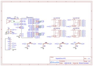
- 1. A A B B C C 1 1 2 2 3 3 4 4 TITLE: DigitalClock RTC REV: 1.0 Date: 2020-03-26 Sheet: 1/1 Drawn By: Shivam Kurzekar Company: - ATMEGA328P-PU U1 PC6 RESET# 1 PD0 RXD 2 PD1 TXD 3 INT0 PD2 4 INT1 PD3 5 T0 PD4 6 VCC 7 GND 8 PB6 XTAL1 9 PB7 XTAL2 10 T1 PD5 11 AIN0 PD6 12 AIN1 PD7 13 PCINT0 PB0 14 PCINT1 PB1 15 PCINT2 PB2 16 PCINT3 PB3 17 PCINT4 PB4 18 PCINT5 PB5 19 AVCC 20 AREF 21 GND 22 PC0 ADC0 23 PC1 ADC1 24 PC2 ADC2 25 PC3 ADC3 26 PC4 ADC4 27 PC5 ADC5 28 HDSP-5501 LED1 COM 3 f 9 g 10 e 1 d 2 COM 8 DP 5 c 4 b 6 a 7 HDSP-5501 LED2 COM 3 f 9 g 10 e 1 d 2 COM 8 DP 5 c 4 b 6 a 7 HDSP-5501 LED4 COM 3 f 9 g 10 e 1 d 2 COM 8 DP 5 c 4 b 6 a 7 HDSP-5501 LED3 COM 3 f 9 g 10 e 1 d 2 COM 8 DP 5 c 4 b 6 a 7 22pF C1 22pF C2 510K R1 16MHz X1 220 R2 220 R3 220 R4 220 R5 220 R6 220 R7 220 R8 220 R9 SW1 1 2 10K R11 10K R10 SW2 1 2 10K R12 SW3 1 2 10K R13 SW4 1 2 DS3231 U2 32K 1 SQW 2 SCL 3 SDA 4 VCC 5 GND 6 GMD12075YB-3V2700 BUZZER1 1 2 GND +5V GND XTAL 1 XTAL 2 5V 5V XTAL 2 XTAL 1 g f e d c b a a b c d e f g a b c d e f g a b c d e f g g f e d c dot a b dot LED2 LED1 LED3 LED4 LED1 LED2 LED3 LED4 SW1 SW2 SW4 SW3 GND 5V SW1 SW2 5V GND SW3 5V GND SW4 5V GND SDA SCL SCL SDA 5V GND