SlideShare una empresa de Scribd logo
1 de 17
Descargar para leer sin conexión
Unit II: MACHINE INSTRUCTIONS and PROGRAMS
This unit deals with concepts as to how programs are executed in the computer from the machine
instruction set viewpoint. All computers deal with numbers. They have instructions that perform
operations on the data operands. Hence we start with basic Number systems.
NUMBER, ARITHMETIC OPERATIONS and CHARACTERS
Binary numbers (0, 1) are used in computers. Various number systems are used in computers.
Numbers in binary are represented as vectors
B=bn-1…b1b0
Unsigned numbers are in range 0 to 2n-1 and are represented by
V (B) =bn-1×2n-1 +…+b1 ×21 +b0 ×20
MSB LSB
Negative Numbers: They can be represented in various ways given below.
• Sign-and-magnitude
Most significant bit determines sign, remaining unsigned bits represent magnitude
• 1’s complement
Most significant bit determines sign. To change sign from unsigned to negative, invert all
the bits ( -3 is obtained by complementing each bit in vector 0011 to yield 1100).
• 2’s complement
Most significant bit determines sign. To change sign from unsigned to negative, invert all
the bits and add 1. This is equivalent to subtracting the positive number from 2n.
The representations are as given in the table below
Figure 1: Binary, signed integer representation
Addition & Subtraction of Signed Numbers: 3 systems of representing signed numbers
These systems differ only in the way they represent negative number
Sign and magnitude system – simplest representation – most awkward for addition and
subtraction. 1’s complement method is somewhat better. 2’s complement is the most efficient
method
Circle representation of Integer Mod N: This is a graphical technique to compute (a+b) mod
16. This can be also used for addition involving signed numbers. Both the cases are shown below
Figure 2:Circle representation of integer Mod 16
The operation (7+4) mod 16 yields the value 11. To perform this graphically using the above
representation locate 7 on the circle and then move 4 units in the clock wise direction to arrive at
the answer 11.
Next let us consider adding +7 to -3. The representation is as shown below
Figure 3: Mod 16 system for 2’s complement numbers
2’s complement representation for 7 is 0111 and -3 is 1101. Thus locate 0111 and then move
1101(13 steps) in clockwise direction to arrive at 0100 = +4.
Some more examples of 2’s complement add and substract operations are as shown in figure
below:
Figure 4: 2’s complement add and substract operations
Overflow in integer arithematic: In 2’s complement arithmetic addition of opposite sign
numbers will never result in overflow . If the numbers are the same sign and the
result is the opposite sign, overflow has occurred.
E.g. 0100 + 0111 =1011 (but 1011 is -5)
In case of unsigned numbers carry out signals that an overflow has occured
Characters: Apart from numbers computers must be able to handle alphanumeric text
information consisting of characters . Characters can be letters of alphabets, decimal digits ,
punctuation marks etc. Most widely used code was ASCII and now a days unicode is being used
widely.
Figure 5: ASCII Codes
Figure 6: Example of Uni Code
MEMORY LOCATIONS and ADDRESSES
Memory consists of storage cells. They store the bits 0 or 1. We can deal with them in n-bit
groups called words (typically 8, 16, 32 or 64 bits). Usually refer to memory size in bytes e.g.
we say we have 128MB memory and rarely use words as the unit. We use addresses to store or
retrieve item of information For some k, memory consists of 2k unique addresses which range
from 0 to 2k -1. The possible addresses are the address space of the computer. E.g. 24-bit address
has 2 24
(16,777,216) locations. Information quantities: bit, byte, word where Byte=8 bits, word
typically varies 16-64 bits. Most machines address memory in units of bytes. For a 32-bit
machine, successive words are at address 0, 4, 8, 12 and so on.
Significant Bytes: Consider the hexadecimal (base 16) 32-bit number 34123F2A. This number
is made up of four bytes 34, 12, 3F, 2A (4x8=32-bits). Bytes/bits with higher weighting are
“more significant” i.e. the byte 34 is more significant than 2A. Bytes/bits with lower weighting
are “less significant” i.e. 2A. Two ways byte addresses can be assigned across words
– More significant bytes first (big endian) - SUN/SPARC, IBM/RISC6000
– Less significant bytes first (little endian) - Intel Pentium Processors
Figure 7: Byte and Word addressing
Big Endian and Little Endian: Consider a 32 bit integer (in hex): 0xabcdef12. It consists of 4
bytes: ab, cd, ef, and 12. Hence this integer will occupy 4 bytes in memory. Say we store it at
memory address starting 1000. There are 24 different orderings possible to store these 4 bytes in
4 locations (1000 - 1003). 2 among these 24 possibilities are very popular. These are called
as little endian and big endian.
INSTRUCTIONS and INSTRUCTION SEQUENCING
A computer must have instruction capable of performing the following operations. They are:
• Data transfer between memory and processor register.
• Arithmetic and logical operations on data.
• Program sequencing and control.
• I/O transfer.
Register Transfer Notation: The possible locations that may be involved during data transfer
are
Memory Location
Processor register
Registers in I/O sub-system.
Location Hardware Binary Address Expression Description
Memory LOC,PLACE,A,VAR2 R1 [LOC] The contents of
memory location LOC
are transferred to the
processor register R1.
Processor R0,R1, R2…Rn [R3] [R1]+[R2] Add the contents of
register R1 &R2 and
the result of the
operation is stored into
register R3.
Assembly Language Notation:
Assembly Language
Format
Description
Move LOC,R1 Transfers the contents of memory location LOC
to the processor register R1.
Add R1,R2,R3 Add the contents of register R1 & R2 and stores
their sum into register R3.
Basic Instruction Type:
Instruction Type Syntax Expression Description
Three Address Operation
Source1,Source2,Destination
Add A,B,C C←[A]+[B]
Two Address Operation
Source,Destination
Add A,B B←[A]+[B]
One Address Operation Operand Add B Content of B
added with
the content of
the
accumulator
INSTRUCTION EXECUTION and STRAIGHT LINE SEQUENCING
Instruction Execution: There are 2 phases for executing an instruction. They are,
• Instruction Fetch
• Instruction Execution
Instruction Fetch:
The instruction is fetched from the memory location whose address is in PC. This is then placed
in IR.
Instruction Execution:
Instruction in IR is examined and decoded to determine which operation is to be performed.
Program execution Steps:
To begin executing a program, the address of first instruction must be placed in PC.
The processor control circuits use the information in the PC to fetch & execute instructions one
at a time in the order of increasing order.
This is called Straight line sequencing. During the execution of each instruction, the PC is
incremented by 4 to point to the address of next instruction.
Figure 8:A program for C [A]+ [B]
Branching: The Address of the memory locations containing the n numbers are symbolically given
as NUM1, NUM2…..NUMn.
Separate Add instruction is used to add each number to the contents of register R0.
After all the numbers have been added, the result is placed in memory location SUM.
Figure 9:A straight line program for adding n numbers
Using loop to add ‘n’ numbers:
• Number of entries in the list „n is stored in memory location M. Register R1 is used as a
counter to determine the number of times the loop is executed.
• Content location M are loaded into register R1 at the beginning of the program.
• It starts at location Loop and ends at the instruction, Branch>0.During each pass, the
address of the next list entry is determined and the entry is fetched and added to R0.
• Decrement R1; It reduces the contents of R1 by 1 each time through the loop.
• Branch >0 Loop; A conditional branch instruction causes a branch only if a specified
condition is satisfied.
Figure 10:Using a loop to add n numbers
Conditional Codes:In order to do conditional branches and other instructions, operations
implicitly set flags. Four commonly used (1-bit) flags
• N (negative) 1 if result –ve else 0
• Z (zero) 1 if result 0 else 0
• V (overflow) 1 if arithmetic overflow occurs else 0
• C (carry) 1 if carry out occurs –ve else 0
ADDRESSING MODE
The different ways in which the location of an operand is specified in an instruction is called as
Addressing mode.
Generic Addressing Modes:
• Immediate mode
• Register mode
• Absolute mode
• Indirect mode
• Index mode
• Base with index
• Base with index and offset
• Relative mode
• Auto-increment mode
• Auto-decrement mode
Implementation of Variables and Constants:
Variables:
The value can be changed as needed using the appropriate instructions. There are 2 accessing
modes to access the variables. They are
• Register Mode
• Absolute Mode
Register Mode:
The operand is the contents of the processor register. The name (address) of the register is given
in the instruction.
Absolute Mode (Direct Mode):
The operand is in a memory location. The address of this location is given explicitly in the
instruction.
The various addressing modes and their assembler syntax and functions are as shown in figure
below:
Figure 11:Generic addressing modes
Immediate Addressing Mode: The operand is specified in the instruction itself .
Move 200immediate, R0
Move #200, R0
Direct Addressing Mode: Operand resides in Memory and its address is given explicitly in the
address field of an instruction.
Move P, R0
Move R0, S
Add Q, R0
Register Addressing Mode: name of the register (address code of a specific general purpose
register) appears in the address field of an instruction i.e.
Move B, R1
Indexing and Arrays:
Index Mode:
The effective address of an operand is generated by adding a constant value to the contents of a
register. The constant value uses either special purpose or general purpose register.
X (RI)
where X – denotes the constant value contained in the instruction
Ri – name of the register involved.
The Effective Address of the operand EA=X + [Ri]
The index register R1 contains the address of a new location and the value of X defines an offset
(also called a displacement).
To find operand first go to Reg R1 (using address)-read the content from R1 i.e. 1000
Add the content 1000 with offset 20 to get the result. Here the constant X refers to the new
address and the contents of index register that defines the offset to the operand.
The sum of two values is given explicitly in the instruction and the other is stored in register.
Add 20(R1), R2 (or) EA=>1000+20=1020
Relative Addressing: It is same as index mode. The difference is, instead of general purpose
register, here we can use program counter (PC).
Relative Mode:
The Effective Address is determined by the Index mode using the PC in place of the general
purpose register.
This mode can be used to access the data operand. But it’s most common use is to specify the
target address in branch instruction. Eg. Branch>0 Loop
It causes the program execution to go to the branch target location. It is identified by the name
loop if the branch condition is satisfied.
Additional Modes:
There are two additional modes. They are
• Auto-increment mode
• Auto-decrement mode
Auto-increment mode: The Effective Address of the operand is the contents of a register in the
instruction. After accessing the operand, the contents of this register is automatically
incremented to point to the next item in the list.
Auto-decrement mode: The Effective Address of the operand is the contents of a register in the
instruction. After accessing the operand, the contents of this register is automatically
decremented to point to the next item in the list.
Assembly Language
We generally use symbolic names to write a program. A complete set of such symbolic names
and rules for their use constitute a programming language, is referred to as assembly language.
LOAD - To load operand from memory
STORE - To store operand to memory
MOVE - To transfer data from one location to another location/Register
Assembler Directives: Directives are the assembler commands to the assembler concerning the
program being assembled. These commands are neither translated into machine opcode nor
assigned any memory location in the object program.
S EQU 150
EQU directs the assembler that the symbolic name S must be replaced with memory location
address 150,
ORIGIN 201
Instruct assembler to initiate data block at main memory locations starting from 201
N DATAWORD 40
Inform the assembler that value of N i.e. data value 40 is to be placed in the memory location
201.
ORIGIN 100
States that assembler directive must load machine instructions of the object program in the main
memory starting from location 100.
END START
End of the program and the label of where program starts
N1 RESERVE 400
Reserve memory block of 400 bytes
Assembler: Has to know
• How to interpret machine language (directives, instructions, addressing modes etc)
• Where to place the instructions in memory
• Where to place the data in memory ; Scans through source program, keeps track of all
names and corresponding numerical values in symbol table e.g. what all the labels mean
• Calculate branch addresses; Forward branch problem – how can it work out forward
addresses?
Two Pass Assembler:
• First pass
– Work out all the addresses of labels
• Second pass
– Generate machine code, substituting values for the labels
BASIC INPUT/OUTPUT OPERATIONS
I/O is the means by which data are transferred between the processor and the outside world.
Devices operate at different speeds to the processor so handshaking is required.
Keyboard/display Example: The keyboard and display are coordinated via software
• Register (on device) assigned to the keyboard hardware
– DATAIN contains ASCII of last typed character
– SINis the status control flag, normally 0. When a character typed, becomes 1.
After the processor reads DATAIN, it is automatically set back to 0
• Register (on device) assigned to the display hardware
– DATAOUT receives a character code
– SOUTis the status control flag. It is 1 when ready to receive a character, set to 0
when the character is being transferred
• These registers form the respective device interface
Figure 12: Bus Connection for processor, keyboard and display
Memory mapped IO and IO mapped IO:
Figure 13: Memory mapped IO and IO mapped IO
I/O Driver program (Programmed IO):
READWAIT Branch to READWAIT if SIN=0
INPUT from DATAIN to R1
WRITEWAIT Branch to WRITEWAIT if SOUT=0
Output from R1 to DATAOUT
Memory Mapped IO:
• On many machines, registers such as DATAIN, DATAOUT are memory-mapped
– Read and write specific memory locations to communicate with device
– Move Byte DATAIN, R1
– Move Byte R1,DATAOUT
• SIN and SOUT might be bits in a device status register e.g. bit 3
READWAIT Branch to READWAIT if SIN=0
INPUT from DATAIN to R1
READWAIT Test bit #3, INSTATUS
Branch=0 READWAIT
Move Byte DATAIN, R1
WRITEWAIT Branch to WRITEWAIT if SOUT=0
Output from R1 to DATAOUT
WRITEWAIT Test bit #3, OUTSTATUS
Branch=0 WRITEWAIT
Move Byte R1, DATAOUT
Program to read a line of character and display it :
Move #LOC,R0 Initialize pointer register R0 to point to
the address of the first location in memory
where the characters are to be stored.
READ TestBit #3,INSTATUS Wait for a character to be entered
Branch=0 READ in the keyboard buffer DATAIN.
MoveByte DATAIN,(R0) Transfer the character from DATAIN into
the memory (this clears SIN to 0)
ECHO TestBit #3, OUTSTATUS Wait for the display to become ready.
Branch=0 ECHO
MoveByte (R0),DATAOUT Move the character just read to the display
buffer register (this clears SOUT to 0).
Compare #CR,(R0)+ Check if the character just read is CR
(carriage return). If it is not CR, then
Branch≠0 READ branch back and read another character.
Also, increment the pointer to store the
next character.
STACKS and QUEUES
List of data elements (usually bytes or words). Elements can only be removed at one end of
the list. Last-in-first-out. Can be implemented in several ways, one way is
– First element placed in BOTTOM
– Grows in direction of decreasing memory address
– Assume 32-bit data
Figure 14: A stack of words in the memory
Stack Implementation:
Subtract #4, SP
Move NEWITEM,(SP) ; push
Move (SP), ITEM; pop
Add #4, SP
With auto increment and auto decrement
Move NEWITEM,-(SP); push
Move (SP) +, ITEM; pop
Queue:
• First-in-first-out
• Unlike a stack, need to keep track of both the front and end for removal and insertion
respectively
• Need two pointers to keep track of both ends
• Assuming it moves through memory in direction of higher addresses, as it is used, it
walks through memory towards higher addresses.
Circular buffers:
• Avoid this problem by limiting to a fixed region in memory
• Start at BEGINNING and entries appended until it reaches END after which it wraps
back around to BEGINNING
• Need to deal with cases when it is completely full and completely empty
SUBROUTINES
• Often need to perform subtask on different data we use subtask called a subroutine
• Rather than include the same sequence of instructions everywhere it is needed, call a
subroutine instead
– One copy of subroutine stored in memory
– Subroutine call causes a branch to the subroutine
– At the end of the subroutine, a return instruction is executed
– Program resumes execution at the instruction immediately following the subroutine call
Parameter Passing:
Subroutine call
– e.g. SUM = listadd (N, NUM);
– N is a variable in memory and NUM is an address pointing to the start of the NUM list
– How do we send the parameters N, NUM to the subroutine?
– How do we receive the return value SUM?
One way is putting the parameters in registers; second way is Passing Parameters on stack and
third way is passing by value and reference.
CISC & RISC
• Multiple length instructions are difficult to implement with high clock rate
• Complex instruction set computers (CISC) have complex instruction encodings like this (e.g.
IA-32)
• Reduced instruction set computers (RISC) only allow simple 32-bit formats, few addressing
modes and all data to be manipulated must be in registers e.g. Add (R3),R2 is not allowed,
instead use Move (R3),R1 followed by Add R1,R2 (e.g. ARM)
RISC machines often are 3-address machines as the addressing mode field is either not necessary
or simplified e.g. Add R1, R2, R3
• CISC machines usually require less instructions but have a lower clock rate, RISC require more
instructions but have a higher clock rate

Más contenido relacionado

La actualidad más candente

Computer organization and architecture
Computer organization and architectureComputer organization and architecture
Computer organization and architectureSubesh Kumar Yadav
 
Chapter 03 arithmetic for computers
Chapter 03   arithmetic for computersChapter 03   arithmetic for computers
Chapter 03 arithmetic for computersBảo Hoang
 
Instruction format
Instruction formatInstruction format
Instruction formatchauhankapil
 
Computer architecture instruction formats
Computer architecture instruction formatsComputer architecture instruction formats
Computer architecture instruction formatsMazin Alwaaly
 
Data transfer and manipulation
Data transfer and manipulationData transfer and manipulation
Data transfer and manipulationSanjeev Patel
 
Pipelining and vector processing
Pipelining and vector processingPipelining and vector processing
Pipelining and vector processingKamal Acharya
 
Coa module1
Coa module1Coa module1
Coa module1cs19club
 
General register organization (computer organization)
General register organization  (computer organization)General register organization  (computer organization)
General register organization (computer organization)rishi ram khanal
 
Instruction codes and computer registers
Instruction codes and computer registersInstruction codes and computer registers
Instruction codes and computer registersSanjeev Patel
 
Memory organization (Computer architecture)
Memory organization (Computer architecture)Memory organization (Computer architecture)
Memory organization (Computer architecture)Sandesh Jonchhe
 
Stack organization
Stack organizationStack organization
Stack organizationchauhankapil
 
Control Units : Microprogrammed and Hardwired:control unit
Control Units : Microprogrammed and Hardwired:control unitControl Units : Microprogrammed and Hardwired:control unit
Control Units : Microprogrammed and Hardwired:control unitabdosaidgkv
 
Computer organisation -morris mano
Computer organisation  -morris manoComputer organisation  -morris mano
Computer organisation -morris manovishnu murthy
 
Register Reference Instructions | Computer Science
Register Reference Instructions | Computer ScienceRegister Reference Instructions | Computer Science
Register Reference Instructions | Computer ScienceTransweb Global Inc
 
Basic ops concept of comp
Basic ops  concept of compBasic ops  concept of comp
Basic ops concept of compgaurav jain
 

La actualidad más candente (20)

Data Hazard and Solution for Data Hazard
Data Hazard and Solution for Data HazardData Hazard and Solution for Data Hazard
Data Hazard and Solution for Data Hazard
 
Cpu organisation
Cpu organisationCpu organisation
Cpu organisation
 
Computer organization and architecture
Computer organization and architectureComputer organization and architecture
Computer organization and architecture
 
Chapter 03 arithmetic for computers
Chapter 03   arithmetic for computersChapter 03   arithmetic for computers
Chapter 03 arithmetic for computers
 
Instruction format
Instruction formatInstruction format
Instruction format
 
Computer architecture instruction formats
Computer architecture instruction formatsComputer architecture instruction formats
Computer architecture instruction formats
 
Data transfer and manipulation
Data transfer and manipulationData transfer and manipulation
Data transfer and manipulation
 
Pipelining and vector processing
Pipelining and vector processingPipelining and vector processing
Pipelining and vector processing
 
Coa module1
Coa module1Coa module1
Coa module1
 
General register organization (computer organization)
General register organization  (computer organization)General register organization  (computer organization)
General register organization (computer organization)
 
Instruction cycle
Instruction cycleInstruction cycle
Instruction cycle
 
Instruction codes and computer registers
Instruction codes and computer registersInstruction codes and computer registers
Instruction codes and computer registers
 
ADDRESSING MODE
ADDRESSING MODEADDRESSING MODE
ADDRESSING MODE
 
ADDRESSING MODES
ADDRESSING MODESADDRESSING MODES
ADDRESSING MODES
 
Memory organization (Computer architecture)
Memory organization (Computer architecture)Memory organization (Computer architecture)
Memory organization (Computer architecture)
 
Stack organization
Stack organizationStack organization
Stack organization
 
Control Units : Microprogrammed and Hardwired:control unit
Control Units : Microprogrammed and Hardwired:control unitControl Units : Microprogrammed and Hardwired:control unit
Control Units : Microprogrammed and Hardwired:control unit
 
Computer organisation -morris mano
Computer organisation  -morris manoComputer organisation  -morris mano
Computer organisation -morris mano
 
Register Reference Instructions | Computer Science
Register Reference Instructions | Computer ScienceRegister Reference Instructions | Computer Science
Register Reference Instructions | Computer Science
 
Basic ops concept of comp
Basic ops  concept of compBasic ops  concept of comp
Basic ops concept of comp
 

Similar a Machine Instructions and Programs Explained

Computer Oraganizaation.pptx
Computer Oraganizaation.pptxComputer Oraganizaation.pptx
Computer Oraganizaation.pptxbmangesh
 
Manoch1raw 160512091436
Manoch1raw 160512091436Manoch1raw 160512091436
Manoch1raw 160512091436marangburu42
 
Digital Electronics- Number systems & codes
Digital Electronics- Number systems & codes Digital Electronics- Number systems & codes
Digital Electronics- Number systems & codes VandanaPagar1
 
Ch12- instruction sets- char & funct.pdf
Ch12- instruction sets- char & funct.pdfCh12- instruction sets- char & funct.pdf
Ch12- instruction sets- char & funct.pdfsaimawarsi
 
chapter one && two.pdf
chapter one && two.pdfchapter one && two.pdf
chapter one && two.pdfmiftah88
 
data representation
 data representation data representation
data representationHaroon_007
 
CS304PC:Computer Organization and Architecture Unit- III PDF notes .pdf
CS304PC:Computer Organization and Architecture Unit- III PDF notes .pdfCS304PC:Computer Organization and Architecture Unit- III PDF notes .pdf
CS304PC:Computer Organization and Architecture Unit- III PDF notes .pdfAsst.prof M.Gokilavani
 
Data representation computer architecture
Data representation  computer architectureData representation  computer architecture
Data representation computer architecturestudy cse
 
Programming the basic computer
Programming the basic computerProgramming the basic computer
Programming the basic computerKamal Acharya
 
Data Reprersentation
Data Reprersentation  Data Reprersentation
Data Reprersentation Kamal Acharya
 
Computer arithmetic operations.pptx
Computer arithmetic operations.pptxComputer arithmetic operations.pptx
Computer arithmetic operations.pptxssusera6fdd5
 
Number Systems.ppt
Number Systems.pptNumber Systems.ppt
Number Systems.pptzorogoh2
 

Similar a Machine Instructions and Programs Explained (20)

Computer Oraganizaation.pptx
Computer Oraganizaation.pptxComputer Oraganizaation.pptx
Computer Oraganizaation.pptx
 
Unit 2 Arithmetic
Unit 2 ArithmeticUnit 2 Arithmetic
Unit 2 Arithmetic
 
Manoch1raw 160512091436
Manoch1raw 160512091436Manoch1raw 160512091436
Manoch1raw 160512091436
 
Digital Electronics- Number systems & codes
Digital Electronics- Number systems & codes Digital Electronics- Number systems & codes
Digital Electronics- Number systems & codes
 
CO_Chapter2.ppt
CO_Chapter2.pptCO_Chapter2.ppt
CO_Chapter2.ppt
 
Ch12- instruction sets- char & funct.pdf
Ch12- instruction sets- char & funct.pdfCh12- instruction sets- char & funct.pdf
Ch12- instruction sets- char & funct.pdf
 
chapter one && two.pdf
chapter one && two.pdfchapter one && two.pdf
chapter one && two.pdf
 
Process.org
Process.orgProcess.org
Process.org
 
data representation
 data representation data representation
data representation
 
CS304PC:Computer Organization and Architecture Unit- III PDF notes .pdf
CS304PC:Computer Organization and Architecture Unit- III PDF notes .pdfCS304PC:Computer Organization and Architecture Unit- III PDF notes .pdf
CS304PC:Computer Organization and Architecture Unit- III PDF notes .pdf
 
Data representation computer architecture
Data representation  computer architectureData representation  computer architecture
Data representation computer architecture
 
Ch 2.pptx
Ch 2.pptxCh 2.pptx
Ch 2.pptx
 
Csc 2313 (lecture 3)
Csc 2313 (lecture 3)Csc 2313 (lecture 3)
Csc 2313 (lecture 3)
 
Csc 2313 (lecture 3)
Csc 2313 (lecture 3)Csc 2313 (lecture 3)
Csc 2313 (lecture 3)
 
Programming the basic computer
Programming the basic computerProgramming the basic computer
Programming the basic computer
 
datareprersentation 1.pptx
datareprersentation 1.pptxdatareprersentation 1.pptx
datareprersentation 1.pptx
 
Data Reprersentation
Data Reprersentation  Data Reprersentation
Data Reprersentation
 
Computer arithmetic operations.pptx
Computer arithmetic operations.pptxComputer arithmetic operations.pptx
Computer arithmetic operations.pptx
 
Number Systems.ppt
Number Systems.pptNumber Systems.ppt
Number Systems.ppt
 
instruction format.pptx
instruction format.pptxinstruction format.pptx
instruction format.pptx
 

Más de Dr.MAYA NAYAK

COMPUTER ORGANIZATION NOTES Unit 7
COMPUTER ORGANIZATION NOTES Unit 7COMPUTER ORGANIZATION NOTES Unit 7
COMPUTER ORGANIZATION NOTES Unit 7Dr.MAYA NAYAK
 
COMPUTER ORGANIZATION NOTES Unit 6
COMPUTER ORGANIZATION NOTES Unit 6COMPUTER ORGANIZATION NOTES Unit 6
COMPUTER ORGANIZATION NOTES Unit 6Dr.MAYA NAYAK
 
COMPUTER ORGANIZATION NOTES Unit 5
COMPUTER ORGANIZATION NOTES Unit 5COMPUTER ORGANIZATION NOTES Unit 5
COMPUTER ORGANIZATION NOTES Unit 5Dr.MAYA NAYAK
 
COMPUTER ORGANIZATION NOTES Unit 3 4
COMPUTER ORGANIZATION NOTES  Unit 3 4COMPUTER ORGANIZATION NOTES  Unit 3 4
COMPUTER ORGANIZATION NOTES Unit 3 4Dr.MAYA NAYAK
 
COMPUTER ORGNAIZATION NOTES
COMPUTER ORGNAIZATION NOTESCOMPUTER ORGNAIZATION NOTES
COMPUTER ORGNAIZATION NOTESDr.MAYA NAYAK
 
Mining of time series data base using fuzzy neural information systems
Mining of time series data base using fuzzy neural information systemsMining of time series data base using fuzzy neural information systems
Mining of time series data base using fuzzy neural information systemsDr.MAYA NAYAK
 
Noinse polution in bhubaneswar city
Noinse polution in bhubaneswar cityNoinse polution in bhubaneswar city
Noinse polution in bhubaneswar cityDr.MAYA NAYAK
 

Más de Dr.MAYA NAYAK (8)

Data structures
Data structuresData structures
Data structures
 
COMPUTER ORGANIZATION NOTES Unit 7
COMPUTER ORGANIZATION NOTES Unit 7COMPUTER ORGANIZATION NOTES Unit 7
COMPUTER ORGANIZATION NOTES Unit 7
 
COMPUTER ORGANIZATION NOTES Unit 6
COMPUTER ORGANIZATION NOTES Unit 6COMPUTER ORGANIZATION NOTES Unit 6
COMPUTER ORGANIZATION NOTES Unit 6
 
COMPUTER ORGANIZATION NOTES Unit 5
COMPUTER ORGANIZATION NOTES Unit 5COMPUTER ORGANIZATION NOTES Unit 5
COMPUTER ORGANIZATION NOTES Unit 5
 
COMPUTER ORGANIZATION NOTES Unit 3 4
COMPUTER ORGANIZATION NOTES  Unit 3 4COMPUTER ORGANIZATION NOTES  Unit 3 4
COMPUTER ORGANIZATION NOTES Unit 3 4
 
COMPUTER ORGNAIZATION NOTES
COMPUTER ORGNAIZATION NOTESCOMPUTER ORGNAIZATION NOTES
COMPUTER ORGNAIZATION NOTES
 
Mining of time series data base using fuzzy neural information systems
Mining of time series data base using fuzzy neural information systemsMining of time series data base using fuzzy neural information systems
Mining of time series data base using fuzzy neural information systems
 
Noinse polution in bhubaneswar city
Noinse polution in bhubaneswar cityNoinse polution in bhubaneswar city
Noinse polution in bhubaneswar city
 

Último

The Most Excellent Way | 1 Corinthians 13
The Most Excellent Way | 1 Corinthians 13The Most Excellent Way | 1 Corinthians 13
The Most Excellent Way | 1 Corinthians 13Steve Thomason
 
social pharmacy d-pharm 1st year by Pragati K. Mahajan
social pharmacy d-pharm 1st year by Pragati K. Mahajansocial pharmacy d-pharm 1st year by Pragati K. Mahajan
social pharmacy d-pharm 1st year by Pragati K. Mahajanpragatimahajan3
 
Measures of Central Tendency: Mean, Median and Mode
Measures of Central Tendency: Mean, Median and ModeMeasures of Central Tendency: Mean, Median and Mode
Measures of Central Tendency: Mean, Median and ModeThiyagu K
 
Arihant handbook biology for class 11 .pdf
Arihant handbook biology for class 11 .pdfArihant handbook biology for class 11 .pdf
Arihant handbook biology for class 11 .pdfchloefrazer622
 
microwave assisted reaction. General introduction
microwave assisted reaction. General introductionmicrowave assisted reaction. General introduction
microwave assisted reaction. General introductionMaksud Ahmed
 
1029 - Danh muc Sach Giao Khoa 10 . pdf
1029 -  Danh muc Sach Giao Khoa 10 . pdf1029 -  Danh muc Sach Giao Khoa 10 . pdf
1029 - Danh muc Sach Giao Khoa 10 . pdfQucHHunhnh
 
Software Engineering Methodologies (overview)
Software Engineering Methodologies (overview)Software Engineering Methodologies (overview)
Software Engineering Methodologies (overview)eniolaolutunde
 
mini mental status format.docx
mini    mental       status     format.docxmini    mental       status     format.docx
mini mental status format.docxPoojaSen20
 
Mastering the Unannounced Regulatory Inspection
Mastering the Unannounced Regulatory InspectionMastering the Unannounced Regulatory Inspection
Mastering the Unannounced Regulatory InspectionSafetyChain Software
 
Russian Call Girls in Andheri Airport Mumbai WhatsApp 9167673311 💞 Full Nigh...
Russian Call Girls in Andheri Airport Mumbai WhatsApp  9167673311 💞 Full Nigh...Russian Call Girls in Andheri Airport Mumbai WhatsApp  9167673311 💞 Full Nigh...
Russian Call Girls in Andheri Airport Mumbai WhatsApp 9167673311 💞 Full Nigh...Pooja Nehwal
 
Activity 01 - Artificial Culture (1).pdf
Activity 01 - Artificial Culture (1).pdfActivity 01 - Artificial Culture (1).pdf
Activity 01 - Artificial Culture (1).pdfciinovamais
 
Q4-W6-Restating Informational Text Grade 3
Q4-W6-Restating Informational Text Grade 3Q4-W6-Restating Informational Text Grade 3
Q4-W6-Restating Informational Text Grade 3JemimahLaneBuaron
 
Accessible design: Minimum effort, maximum impact
Accessible design: Minimum effort, maximum impactAccessible design: Minimum effort, maximum impact
Accessible design: Minimum effort, maximum impactdawncurless
 
9548086042 for call girls in Indira Nagar with room service
9548086042  for call girls in Indira Nagar  with room service9548086042  for call girls in Indira Nagar  with room service
9548086042 for call girls in Indira Nagar with room servicediscovermytutordmt
 
Introduction to Nonprofit Accounting: The Basics
Introduction to Nonprofit Accounting: The BasicsIntroduction to Nonprofit Accounting: The Basics
Introduction to Nonprofit Accounting: The BasicsTechSoup
 
POINT- BIOCHEMISTRY SEM 2 ENZYMES UNIT 5.pptx
POINT- BIOCHEMISTRY SEM 2 ENZYMES UNIT 5.pptxPOINT- BIOCHEMISTRY SEM 2 ENZYMES UNIT 5.pptx
POINT- BIOCHEMISTRY SEM 2 ENZYMES UNIT 5.pptxSayali Powar
 
A Critique of the Proposed National Education Policy Reform
A Critique of the Proposed National Education Policy ReformA Critique of the Proposed National Education Policy Reform
A Critique of the Proposed National Education Policy ReformChameera Dedduwage
 
Student login on Anyboli platform.helpin
Student login on Anyboli platform.helpinStudent login on Anyboli platform.helpin
Student login on Anyboli platform.helpinRaunakKeshri1
 

Último (20)

The Most Excellent Way | 1 Corinthians 13
The Most Excellent Way | 1 Corinthians 13The Most Excellent Way | 1 Corinthians 13
The Most Excellent Way | 1 Corinthians 13
 
social pharmacy d-pharm 1st year by Pragati K. Mahajan
social pharmacy d-pharm 1st year by Pragati K. Mahajansocial pharmacy d-pharm 1st year by Pragati K. Mahajan
social pharmacy d-pharm 1st year by Pragati K. Mahajan
 
Measures of Central Tendency: Mean, Median and Mode
Measures of Central Tendency: Mean, Median and ModeMeasures of Central Tendency: Mean, Median and Mode
Measures of Central Tendency: Mean, Median and Mode
 
Arihant handbook biology for class 11 .pdf
Arihant handbook biology for class 11 .pdfArihant handbook biology for class 11 .pdf
Arihant handbook biology for class 11 .pdf
 
microwave assisted reaction. General introduction
microwave assisted reaction. General introductionmicrowave assisted reaction. General introduction
microwave assisted reaction. General introduction
 
1029 - Danh muc Sach Giao Khoa 10 . pdf
1029 -  Danh muc Sach Giao Khoa 10 . pdf1029 -  Danh muc Sach Giao Khoa 10 . pdf
1029 - Danh muc Sach Giao Khoa 10 . pdf
 
Software Engineering Methodologies (overview)
Software Engineering Methodologies (overview)Software Engineering Methodologies (overview)
Software Engineering Methodologies (overview)
 
mini mental status format.docx
mini    mental       status     format.docxmini    mental       status     format.docx
mini mental status format.docx
 
Mastering the Unannounced Regulatory Inspection
Mastering the Unannounced Regulatory InspectionMastering the Unannounced Regulatory Inspection
Mastering the Unannounced Regulatory Inspection
 
Russian Call Girls in Andheri Airport Mumbai WhatsApp 9167673311 💞 Full Nigh...
Russian Call Girls in Andheri Airport Mumbai WhatsApp  9167673311 💞 Full Nigh...Russian Call Girls in Andheri Airport Mumbai WhatsApp  9167673311 💞 Full Nigh...
Russian Call Girls in Andheri Airport Mumbai WhatsApp 9167673311 💞 Full Nigh...
 
Advance Mobile Application Development class 07
Advance Mobile Application Development class 07Advance Mobile Application Development class 07
Advance Mobile Application Development class 07
 
Código Creativo y Arte de Software | Unidad 1
Código Creativo y Arte de Software | Unidad 1Código Creativo y Arte de Software | Unidad 1
Código Creativo y Arte de Software | Unidad 1
 
Activity 01 - Artificial Culture (1).pdf
Activity 01 - Artificial Culture (1).pdfActivity 01 - Artificial Culture (1).pdf
Activity 01 - Artificial Culture (1).pdf
 
Q4-W6-Restating Informational Text Grade 3
Q4-W6-Restating Informational Text Grade 3Q4-W6-Restating Informational Text Grade 3
Q4-W6-Restating Informational Text Grade 3
 
Accessible design: Minimum effort, maximum impact
Accessible design: Minimum effort, maximum impactAccessible design: Minimum effort, maximum impact
Accessible design: Minimum effort, maximum impact
 
9548086042 for call girls in Indira Nagar with room service
9548086042  for call girls in Indira Nagar  with room service9548086042  for call girls in Indira Nagar  with room service
9548086042 for call girls in Indira Nagar with room service
 
Introduction to Nonprofit Accounting: The Basics
Introduction to Nonprofit Accounting: The BasicsIntroduction to Nonprofit Accounting: The Basics
Introduction to Nonprofit Accounting: The Basics
 
POINT- BIOCHEMISTRY SEM 2 ENZYMES UNIT 5.pptx
POINT- BIOCHEMISTRY SEM 2 ENZYMES UNIT 5.pptxPOINT- BIOCHEMISTRY SEM 2 ENZYMES UNIT 5.pptx
POINT- BIOCHEMISTRY SEM 2 ENZYMES UNIT 5.pptx
 
A Critique of the Proposed National Education Policy Reform
A Critique of the Proposed National Education Policy ReformA Critique of the Proposed National Education Policy Reform
A Critique of the Proposed National Education Policy Reform
 
Student login on Anyboli platform.helpin
Student login on Anyboli platform.helpinStudent login on Anyboli platform.helpin
Student login on Anyboli platform.helpin
 

Machine Instructions and Programs Explained

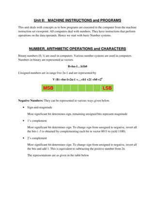
  • 1. Unit II: MACHINE INSTRUCTIONS and PROGRAMS This unit deals with concepts as to how programs are executed in the computer from the machine instruction set viewpoint. All computers deal with numbers. They have instructions that perform operations on the data operands. Hence we start with basic Number systems. NUMBER, ARITHMETIC OPERATIONS and CHARACTERS Binary numbers (0, 1) are used in computers. Various number systems are used in computers. Numbers in binary are represented as vectors B=bn-1…b1b0 Unsigned numbers are in range 0 to 2n-1 and are represented by V (B) =bn-1×2n-1 +…+b1 ×21 +b0 ×20 MSB LSB Negative Numbers: They can be represented in various ways given below. • Sign-and-magnitude Most significant bit determines sign, remaining unsigned bits represent magnitude • 1’s complement Most significant bit determines sign. To change sign from unsigned to negative, invert all the bits ( -3 is obtained by complementing each bit in vector 0011 to yield 1100). • 2’s complement Most significant bit determines sign. To change sign from unsigned to negative, invert all the bits and add 1. This is equivalent to subtracting the positive number from 2n. The representations are as given in the table below
  • 2. Figure 1: Binary, signed integer representation Addition & Subtraction of Signed Numbers: 3 systems of representing signed numbers These systems differ only in the way they represent negative number Sign and magnitude system – simplest representation – most awkward for addition and subtraction. 1’s complement method is somewhat better. 2’s complement is the most efficient method Circle representation of Integer Mod N: This is a graphical technique to compute (a+b) mod 16. This can be also used for addition involving signed numbers. Both the cases are shown below Figure 2:Circle representation of integer Mod 16
  • 3. The operation (7+4) mod 16 yields the value 11. To perform this graphically using the above representation locate 7 on the circle and then move 4 units in the clock wise direction to arrive at the answer 11. Next let us consider adding +7 to -3. The representation is as shown below Figure 3: Mod 16 system for 2’s complement numbers 2’s complement representation for 7 is 0111 and -3 is 1101. Thus locate 0111 and then move 1101(13 steps) in clockwise direction to arrive at 0100 = +4. Some more examples of 2’s complement add and substract operations are as shown in figure below: Figure 4: 2’s complement add and substract operations
  • 4. Overflow in integer arithematic: In 2’s complement arithmetic addition of opposite sign numbers will never result in overflow . If the numbers are the same sign and the result is the opposite sign, overflow has occurred. E.g. 0100 + 0111 =1011 (but 1011 is -5) In case of unsigned numbers carry out signals that an overflow has occured Characters: Apart from numbers computers must be able to handle alphanumeric text information consisting of characters . Characters can be letters of alphabets, decimal digits , punctuation marks etc. Most widely used code was ASCII and now a days unicode is being used widely. Figure 5: ASCII Codes Figure 6: Example of Uni Code
  • 5. MEMORY LOCATIONS and ADDRESSES Memory consists of storage cells. They store the bits 0 or 1. We can deal with them in n-bit groups called words (typically 8, 16, 32 or 64 bits). Usually refer to memory size in bytes e.g. we say we have 128MB memory and rarely use words as the unit. We use addresses to store or retrieve item of information For some k, memory consists of 2k unique addresses which range from 0 to 2k -1. The possible addresses are the address space of the computer. E.g. 24-bit address has 2 24 (16,777,216) locations. Information quantities: bit, byte, word where Byte=8 bits, word typically varies 16-64 bits. Most machines address memory in units of bytes. For a 32-bit machine, successive words are at address 0, 4, 8, 12 and so on. Significant Bytes: Consider the hexadecimal (base 16) 32-bit number 34123F2A. This number is made up of four bytes 34, 12, 3F, 2A (4x8=32-bits). Bytes/bits with higher weighting are “more significant” i.e. the byte 34 is more significant than 2A. Bytes/bits with lower weighting are “less significant” i.e. 2A. Two ways byte addresses can be assigned across words – More significant bytes first (big endian) - SUN/SPARC, IBM/RISC6000 – Less significant bytes first (little endian) - Intel Pentium Processors Figure 7: Byte and Word addressing
  • 6. Big Endian and Little Endian: Consider a 32 bit integer (in hex): 0xabcdef12. It consists of 4 bytes: ab, cd, ef, and 12. Hence this integer will occupy 4 bytes in memory. Say we store it at memory address starting 1000. There are 24 different orderings possible to store these 4 bytes in 4 locations (1000 - 1003). 2 among these 24 possibilities are very popular. These are called as little endian and big endian. INSTRUCTIONS and INSTRUCTION SEQUENCING A computer must have instruction capable of performing the following operations. They are: • Data transfer between memory and processor register. • Arithmetic and logical operations on data. • Program sequencing and control. • I/O transfer. Register Transfer Notation: The possible locations that may be involved during data transfer are Memory Location Processor register Registers in I/O sub-system. Location Hardware Binary Address Expression Description Memory LOC,PLACE,A,VAR2 R1 [LOC] The contents of memory location LOC are transferred to the processor register R1. Processor R0,R1, R2…Rn [R3] [R1]+[R2] Add the contents of register R1 &R2 and the result of the operation is stored into register R3.
  • 7. Assembly Language Notation: Assembly Language Format Description Move LOC,R1 Transfers the contents of memory location LOC to the processor register R1. Add R1,R2,R3 Add the contents of register R1 & R2 and stores their sum into register R3. Basic Instruction Type: Instruction Type Syntax Expression Description Three Address Operation Source1,Source2,Destination Add A,B,C C←[A]+[B] Two Address Operation Source,Destination Add A,B B←[A]+[B] One Address Operation Operand Add B Content of B added with the content of the accumulator INSTRUCTION EXECUTION and STRAIGHT LINE SEQUENCING Instruction Execution: There are 2 phases for executing an instruction. They are, • Instruction Fetch • Instruction Execution Instruction Fetch: The instruction is fetched from the memory location whose address is in PC. This is then placed in IR. Instruction Execution: Instruction in IR is examined and decoded to determine which operation is to be performed. Program execution Steps: To begin executing a program, the address of first instruction must be placed in PC. The processor control circuits use the information in the PC to fetch & execute instructions one at a time in the order of increasing order. This is called Straight line sequencing. During the execution of each instruction, the PC is incremented by 4 to point to the address of next instruction.
  • 8. Figure 8:A program for C [A]+ [B] Branching: The Address of the memory locations containing the n numbers are symbolically given as NUM1, NUM2…..NUMn. Separate Add instruction is used to add each number to the contents of register R0. After all the numbers have been added, the result is placed in memory location SUM. Figure 9:A straight line program for adding n numbers
  • 9. Using loop to add ‘n’ numbers: • Number of entries in the list „n is stored in memory location M. Register R1 is used as a counter to determine the number of times the loop is executed. • Content location M are loaded into register R1 at the beginning of the program. • It starts at location Loop and ends at the instruction, Branch>0.During each pass, the address of the next list entry is determined and the entry is fetched and added to R0. • Decrement R1; It reduces the contents of R1 by 1 each time through the loop. • Branch >0 Loop; A conditional branch instruction causes a branch only if a specified condition is satisfied. Figure 10:Using a loop to add n numbers Conditional Codes:In order to do conditional branches and other instructions, operations implicitly set flags. Four commonly used (1-bit) flags • N (negative) 1 if result –ve else 0 • Z (zero) 1 if result 0 else 0 • V (overflow) 1 if arithmetic overflow occurs else 0 • C (carry) 1 if carry out occurs –ve else 0
  • 10. ADDRESSING MODE The different ways in which the location of an operand is specified in an instruction is called as Addressing mode. Generic Addressing Modes: • Immediate mode • Register mode • Absolute mode • Indirect mode • Index mode • Base with index • Base with index and offset • Relative mode • Auto-increment mode • Auto-decrement mode Implementation of Variables and Constants: Variables: The value can be changed as needed using the appropriate instructions. There are 2 accessing modes to access the variables. They are • Register Mode • Absolute Mode Register Mode: The operand is the contents of the processor register. The name (address) of the register is given in the instruction. Absolute Mode (Direct Mode): The operand is in a memory location. The address of this location is given explicitly in the instruction. The various addressing modes and their assembler syntax and functions are as shown in figure below: Figure 11:Generic addressing modes
  • 11. Immediate Addressing Mode: The operand is specified in the instruction itself . Move 200immediate, R0 Move #200, R0 Direct Addressing Mode: Operand resides in Memory and its address is given explicitly in the address field of an instruction. Move P, R0 Move R0, S Add Q, R0 Register Addressing Mode: name of the register (address code of a specific general purpose register) appears in the address field of an instruction i.e. Move B, R1 Indexing and Arrays: Index Mode: The effective address of an operand is generated by adding a constant value to the contents of a register. The constant value uses either special purpose or general purpose register. X (RI) where X – denotes the constant value contained in the instruction Ri – name of the register involved. The Effective Address of the operand EA=X + [Ri] The index register R1 contains the address of a new location and the value of X defines an offset (also called a displacement). To find operand first go to Reg R1 (using address)-read the content from R1 i.e. 1000 Add the content 1000 with offset 20 to get the result. Here the constant X refers to the new address and the contents of index register that defines the offset to the operand. The sum of two values is given explicitly in the instruction and the other is stored in register. Add 20(R1), R2 (or) EA=>1000+20=1020 Relative Addressing: It is same as index mode. The difference is, instead of general purpose register, here we can use program counter (PC). Relative Mode: The Effective Address is determined by the Index mode using the PC in place of the general purpose register. This mode can be used to access the data operand. But it’s most common use is to specify the target address in branch instruction. Eg. Branch>0 Loop It causes the program execution to go to the branch target location. It is identified by the name loop if the branch condition is satisfied.
  • 12. Additional Modes: There are two additional modes. They are • Auto-increment mode • Auto-decrement mode Auto-increment mode: The Effective Address of the operand is the contents of a register in the instruction. After accessing the operand, the contents of this register is automatically incremented to point to the next item in the list. Auto-decrement mode: The Effective Address of the operand is the contents of a register in the instruction. After accessing the operand, the contents of this register is automatically decremented to point to the next item in the list. Assembly Language We generally use symbolic names to write a program. A complete set of such symbolic names and rules for their use constitute a programming language, is referred to as assembly language. LOAD - To load operand from memory STORE - To store operand to memory MOVE - To transfer data from one location to another location/Register Assembler Directives: Directives are the assembler commands to the assembler concerning the program being assembled. These commands are neither translated into machine opcode nor assigned any memory location in the object program. S EQU 150 EQU directs the assembler that the symbolic name S must be replaced with memory location address 150, ORIGIN 201 Instruct assembler to initiate data block at main memory locations starting from 201 N DATAWORD 40 Inform the assembler that value of N i.e. data value 40 is to be placed in the memory location 201. ORIGIN 100 States that assembler directive must load machine instructions of the object program in the main memory starting from location 100. END START End of the program and the label of where program starts N1 RESERVE 400 Reserve memory block of 400 bytes
  • 13. Assembler: Has to know • How to interpret machine language (directives, instructions, addressing modes etc) • Where to place the instructions in memory • Where to place the data in memory ; Scans through source program, keeps track of all names and corresponding numerical values in symbol table e.g. what all the labels mean • Calculate branch addresses; Forward branch problem – how can it work out forward addresses? Two Pass Assembler: • First pass – Work out all the addresses of labels • Second pass – Generate machine code, substituting values for the labels BASIC INPUT/OUTPUT OPERATIONS I/O is the means by which data are transferred between the processor and the outside world. Devices operate at different speeds to the processor so handshaking is required. Keyboard/display Example: The keyboard and display are coordinated via software • Register (on device) assigned to the keyboard hardware – DATAIN contains ASCII of last typed character – SINis the status control flag, normally 0. When a character typed, becomes 1. After the processor reads DATAIN, it is automatically set back to 0 • Register (on device) assigned to the display hardware – DATAOUT receives a character code – SOUTis the status control flag. It is 1 when ready to receive a character, set to 0 when the character is being transferred • These registers form the respective device interface Figure 12: Bus Connection for processor, keyboard and display
  • 14. Memory mapped IO and IO mapped IO: Figure 13: Memory mapped IO and IO mapped IO I/O Driver program (Programmed IO): READWAIT Branch to READWAIT if SIN=0 INPUT from DATAIN to R1 WRITEWAIT Branch to WRITEWAIT if SOUT=0 Output from R1 to DATAOUT Memory Mapped IO: • On many machines, registers such as DATAIN, DATAOUT are memory-mapped – Read and write specific memory locations to communicate with device – Move Byte DATAIN, R1 – Move Byte R1,DATAOUT • SIN and SOUT might be bits in a device status register e.g. bit 3 READWAIT Branch to READWAIT if SIN=0 INPUT from DATAIN to R1 READWAIT Test bit #3, INSTATUS Branch=0 READWAIT Move Byte DATAIN, R1
  • 15. WRITEWAIT Branch to WRITEWAIT if SOUT=0 Output from R1 to DATAOUT WRITEWAIT Test bit #3, OUTSTATUS Branch=0 WRITEWAIT Move Byte R1, DATAOUT Program to read a line of character and display it : Move #LOC,R0 Initialize pointer register R0 to point to the address of the first location in memory where the characters are to be stored. READ TestBit #3,INSTATUS Wait for a character to be entered Branch=0 READ in the keyboard buffer DATAIN. MoveByte DATAIN,(R0) Transfer the character from DATAIN into the memory (this clears SIN to 0) ECHO TestBit #3, OUTSTATUS Wait for the display to become ready. Branch=0 ECHO MoveByte (R0),DATAOUT Move the character just read to the display buffer register (this clears SOUT to 0). Compare #CR,(R0)+ Check if the character just read is CR (carriage return). If it is not CR, then Branch≠0 READ branch back and read another character. Also, increment the pointer to store the next character. STACKS and QUEUES List of data elements (usually bytes or words). Elements can only be removed at one end of the list. Last-in-first-out. Can be implemented in several ways, one way is – First element placed in BOTTOM – Grows in direction of decreasing memory address – Assume 32-bit data
  • 16. Figure 14: A stack of words in the memory Stack Implementation: Subtract #4, SP Move NEWITEM,(SP) ; push Move (SP), ITEM; pop Add #4, SP With auto increment and auto decrement Move NEWITEM,-(SP); push Move (SP) +, ITEM; pop Queue: • First-in-first-out • Unlike a stack, need to keep track of both the front and end for removal and insertion respectively • Need two pointers to keep track of both ends • Assuming it moves through memory in direction of higher addresses, as it is used, it walks through memory towards higher addresses. Circular buffers: • Avoid this problem by limiting to a fixed region in memory • Start at BEGINNING and entries appended until it reaches END after which it wraps back around to BEGINNING • Need to deal with cases when it is completely full and completely empty
  • 17. SUBROUTINES • Often need to perform subtask on different data we use subtask called a subroutine • Rather than include the same sequence of instructions everywhere it is needed, call a subroutine instead – One copy of subroutine stored in memory – Subroutine call causes a branch to the subroutine – At the end of the subroutine, a return instruction is executed – Program resumes execution at the instruction immediately following the subroutine call Parameter Passing: Subroutine call – e.g. SUM = listadd (N, NUM); – N is a variable in memory and NUM is an address pointing to the start of the NUM list – How do we send the parameters N, NUM to the subroutine? – How do we receive the return value SUM? One way is putting the parameters in registers; second way is Passing Parameters on stack and third way is passing by value and reference. CISC & RISC • Multiple length instructions are difficult to implement with high clock rate • Complex instruction set computers (CISC) have complex instruction encodings like this (e.g. IA-32) • Reduced instruction set computers (RISC) only allow simple 32-bit formats, few addressing modes and all data to be manipulated must be in registers e.g. Add (R3),R2 is not allowed, instead use Move (R3),R1 followed by Add R1,R2 (e.g. ARM) RISC machines often are 3-address machines as the addressing mode field is either not necessary or simplified e.g. Add R1, R2, R3 • CISC machines usually require less instructions but have a lower clock rate, RISC require more instructions but have a higher clock rate