SlideShare una empresa de Scribd logo
1 de 8
Descargar para leer sin conexión
386
Motor driver ICs
Reversible motor driver
BA6209 / BA6209N
The BA6209 and BA6209N are reversible-motor drivers suitable for brush motors. Two logic inputs allow three output
modes : forward, reverse, and braking. The motor revolving speed can be set arbitrarily by controlling the voltage applied
to the motor with the control pin voltage VR.
FApplications
VCRs and cassette tape recorders
FFeatures
1) Power transistors can handle a large current
(1.6A maximally).
2) Brake is applied when stopping the motor.
3) Built-in function to absorb rush currents generated by
reversing and braking.
4) Motor speed controlling pin.
5) Small standby current.
(VCC = 12V, IO = 5.5mA typically)
6) Stable operation during mode changes either from
forward to reverse or vice versa.
7) Interface with CMOS devices.
FBlock diagram
387
Motor driver ICs BA6209 / BA6209N
FAbsolute maximum ratings (Ta = 25_C)
FRecommended operating conditions (Ta = 25_C)
FElectrical characteristics (unless otherwise noted, Ta = 25_C and VCC = 12V)
FElectrical characteristic curves
388
Motor driver ICs BA6209 / BA6209N
389
Motor driver ICs BA6209 / BA6209N
FMeasurement circuit
390
Motor driver ICs BA6209 / BA6209N
FCircuit operation
Input / output truth table
Forward / reverse control, forced stop, and rush current
absorption are controlled by the combination of FIN and
RIN input states.
(1) Forward / reverse control circuit
When FIN is HIGH and RIN is LOW, current flows from
OUT1 to OUT2. When FIN is LOW and RIN is HIGH, cur-
rent flows from OUT2 to OUT1 (refer to the truth table).
(2) Forced stop circuit
By setting RIN and FIN both HIGH or both LOW, power
supply to the motor is shut down and a brake is applied
by absorbing the motor counter-electromotive force.
(3) Rush current absorption circuit
When a high voltage (caused by such as a motor rever-
sal) is generated on OUT1 and OUT2, an internal
comparator detects the high voltage and turns on an in-
ternal circuit that absorbs rush currents.
(4) Drive circuit
The forward direction of the motor connected between
OUT1 and OUT2 corresponds to the current flow from
OUT1 to OUT2, and the reverse direction corresponds to
the current flow from OUT2 to OUT1. The output voltage
(VOUT) applied to the motor is given by the equation :
VOUT (V) = VZD * VCE (sat.) = VZD * 0.2 (IOUT = 100mA)
where VZD is the zener voltage of the constant voltage
diode (ZD) connected to pin 4.
If Vref is left OPEN, the output voltage (VOUT) is given by
the equation :
VOUT (V) = VCC1 * VCE (sat.) (PNP) * 2VF * VCE (sat.)
= VCC1 * 1.8 (IOUT = 100mA)
FPin descriptions
391
Motor driver ICs BA6209 / BA6209N
FOperation notes
(1) Resistor dividing IC power consumption
To reduce power dissipated in the IC, a resistance (about
3X10Ω) must always be connected between VCC and the
power supply pin of the driver circuit. If VCC2 is connected
to VCC with no resistor, the IC can be damaged by over-
current when operated at the voltage range close to the
maximum operating voltage.
(2) Control signal waveform
The rise and fall times of signals applied to the control
pins should be 5ms or less. Longer times can cause er-
ratic operation of the internal logic circuits and may result
in damage to the driver circuits.
For example, if the supply voltage for the external control
circuit comes up after the supply voltage of the IC, the ris-
ing edge of the control signal slowly follows the rise of the
externalsupply voltage. This could result in erratic opera-
tion or damage to the IC due to excess currents.
(3) IC ground voltage
To provide separation between the circuit elements with-
in the IC, the GND pin of the IC must always be held at
a lower potential than the other pins.
If the potential of the GND pin is allowed to rise above that
of other pins (such as the control input pins), separation
between the internal circuit elements could break down,
resulting in erratic operation or internal damage.
For example, a resistor may be connected between GND
(pin 1) and the ground as shown in Fig. 19, when detect-
ing and controlling the motor operating current. In this
case, the potential of pin 1 would be above the ground po-
tential by an amount equal to the voltage drop across the
resistor. Therefore, dropping the input pin potential to the
ground potential would have the effect of applying a neg-
ative voltage to the input pin.
This should be avoided by detecting the motor operating
current in a way shown in Fig. 20.
(4) Input pins
Voltage should never be applied to the input pins when
the VCC voltage is not applied to the IC. Similarly, when
VCC is applied, the voltage on each input pin should be
less than VCC and within the guaranteed range for the
electrical characteristics.
(5) Back-rush voltage
Depending on the ambient conditions, environment, or
motor characteristics, the back-rush voltage may fluctu-
ate. Be sure to confirm that the back-rush voltage will not
adversely affect the operation of the IC.
(6) Large current line
Largecurrents are carried by the motor power supply and
motor ground for these ICs.
Therefore, the layout of the pattern of the PC board and
the constants of certain parameters for external compo-
nents, such as the capacitor between the power supply
and ground, may cause this large output current to flow
back to the input pins, resulting in output oscillation or
other malfunctions. To prevent this, make sure that the
PC board layout and external circuit constants cause no
problems with the characteristics of these ICs.
(7) Power dissipation
The power dissipation will fluctuate depending on the
mounting conditions of the IC and the ambient environ-
ment. Make sure to carefully check the thermal design of
the application where these ICs sill be used.
(8) Power consumption
The power consumption by the IC varies widely with the
power supply voltage and the output current. Give full
consideration to the power dissipation rating and the
thermal resistance data and transient thermal resistance
data, to provide a thermal design so that none of the rat-
ings for the IC are exceeded.
392
Motor driver ICs BA6209 / BA6209N
(9) ASO
Make sure that the output current and supply voltage do
not exceed the ASO values.
(10) Precautions for input mode switching
To ensure reliability, it is recommended that the mode
switching for the motor pass once through the open
mode.
(11) There are no circuits built into these ICs that pre-
vent in-rush currents. Therefore, it is recommended to
place a current limiting resistor or other physical counter-
measure.
(12) If the potential of the output pin sways greatly and
goes below the potential of ground, the operation of the
IC may malfunction or be adversely affected. In such a
case, place a diode between the output and ground, or
other measure, to prevent this.
(13) The quality of these products have been carefully
checked; however, use of the products with applied volt-
ages, operating temperatures, or other parameters that
exceed the absolute maximum rating given may result in
the damage of the IC and the product it is used in. If the
IC is damaged, the short mode and open modes cannot
be specified, so if the IC is to be used in applications
where parameters may exceed the absolute maximum
ratings, then be sure to incorporate fuses, or other physi-
cal safety measures.
393
Motor driver ICs BA6209 / BA6209N
FApplication example
FExternal dimensions (Units: mm)

Más contenido relacionado

La actualidad más candente

Shubham chamoli 132 kv substation presenttation
Shubham  chamoli 132 kv substation presenttationShubham  chamoli 132 kv substation presenttation
Shubham chamoli 132 kv substation presenttationshubhamchamoli
 
Static excitation-system
Static excitation-systemStatic excitation-system
Static excitation-systemDeepak Jha
 
Alternator excitation systems
Alternator excitation systemsAlternator excitation systems
Alternator excitation systemsMD AlBeruni
 
SPEED CONTROL OF SEPARATELY EXCITED DC MOTOR USING POWER ELECTRONIC CONVERTER
 SPEED CONTROL OF SEPARATELY EXCITED DC MOTOR USING POWER ELECTRONIC CONVERTER  SPEED CONTROL OF SEPARATELY EXCITED DC MOTOR USING POWER ELECTRONIC CONVERTER
SPEED CONTROL OF SEPARATELY EXCITED DC MOTOR USING POWER ELECTRONIC CONVERTER ijiert bestjournal
 
Power Plant Horror Stories
Power Plant Horror StoriesPower Plant Horror Stories
Power Plant Horror Storiesmichaeljmack
 
EXCITATION SYSTEMS by Dr. Kundur Power Systems
EXCITATION SYSTEMS by Dr. Kundur Power SystemsEXCITATION SYSTEMS by Dr. Kundur Power Systems
EXCITATION SYSTEMS by Dr. Kundur Power SystemsPower System Operation
 
Motor Control Relay, Pwm, DC and Stepper Motors
Motor Control Relay, Pwm, DC and Stepper MotorsMotor Control Relay, Pwm, DC and Stepper Motors
Motor Control Relay, Pwm, DC and Stepper MotorsDevashish Raval
 
Vfd checking voltagefrequency ratio on variablespeed drives with a fluke scop...
Vfd checking voltagefrequency ratio on variablespeed drives with a fluke scop...Vfd checking voltagefrequency ratio on variablespeed drives with a fluke scop...
Vfd checking voltagefrequency ratio on variablespeed drives with a fluke scop...Zhaoyi Fang
 
Speed control of single phase induction motor with variable frequency voltage...
Speed control of single phase induction motor with variable frequency voltage...Speed control of single phase induction motor with variable frequency voltage...
Speed control of single phase induction motor with variable frequency voltage...SHAHRUKH ALAM
 
Dc motor interfacing with 8051 microcontroller
Dc motor interfacing with 8051 microcontrollerDc motor interfacing with 8051 microcontroller
Dc motor interfacing with 8051 microcontrollerUmar Shuaib
 
9. aircraft electrical systems
9. aircraft electrical systems9. aircraft electrical systems
9. aircraft electrical systemsTauseef khan
 
Speed Control Of Single Phase Induction Motor
Speed Control Of Single Phase Induction MotorSpeed Control Of Single Phase Induction Motor
Speed Control Of Single Phase Induction MotorBhuban Chandra Mohanta
 
Brushless excitation
Brushless excitationBrushless excitation
Brushless excitationsuperbhuppi
 
Excitation Synchronous Wind Power Generators With Maximum Power Tracking Scheme
Excitation Synchronous Wind Power Generators With Maximum Power Tracking SchemeExcitation Synchronous Wind Power Generators With Maximum Power Tracking Scheme
Excitation Synchronous Wind Power Generators With Maximum Power Tracking SchemeProjectsatbangalore
 
Excitation System & capability curve of synchronous generator
Excitation System &  capability curve of synchronous generatorExcitation System &  capability curve of synchronous generator
Excitation System & capability curve of synchronous generatorMANOJ KUMAR MAHARANA
 
Research Inventy : International Journal of Engineering and Science is publis...
Research Inventy : International Journal of Engineering and Science is publis...Research Inventy : International Journal of Engineering and Science is publis...
Research Inventy : International Journal of Engineering and Science is publis...researchinventy
 
Speed control of 1 φ inducton motor using traic
Speed control of 1 φ inducton motor using traicSpeed control of 1 φ inducton motor using traic
Speed control of 1 φ inducton motor using traicjawededu
 
Single phase induction motor(eee499.blogspot.com)
Single phase induction motor(eee499.blogspot.com)Single phase induction motor(eee499.blogspot.com)
Single phase induction motor(eee499.blogspot.com)slmnsvn
 

La actualidad más candente (20)

Shubham chamoli 132 kv substation presenttation
Shubham  chamoli 132 kv substation presenttationShubham  chamoli 132 kv substation presenttation
Shubham chamoli 132 kv substation presenttation
 
Hamza Kazmi (GTE)
Hamza Kazmi (GTE)Hamza Kazmi (GTE)
Hamza Kazmi (GTE)
 
Static excitation-system
Static excitation-systemStatic excitation-system
Static excitation-system
 
Alternator excitation systems
Alternator excitation systemsAlternator excitation systems
Alternator excitation systems
 
SPEED CONTROL OF SEPARATELY EXCITED DC MOTOR USING POWER ELECTRONIC CONVERTER
 SPEED CONTROL OF SEPARATELY EXCITED DC MOTOR USING POWER ELECTRONIC CONVERTER  SPEED CONTROL OF SEPARATELY EXCITED DC MOTOR USING POWER ELECTRONIC CONVERTER
SPEED CONTROL OF SEPARATELY EXCITED DC MOTOR USING POWER ELECTRONIC CONVERTER
 
Power Plant Horror Stories
Power Plant Horror StoriesPower Plant Horror Stories
Power Plant Horror Stories
 
EXCITATION SYSTEMS by Dr. Kundur Power Systems
EXCITATION SYSTEMS by Dr. Kundur Power SystemsEXCITATION SYSTEMS by Dr. Kundur Power Systems
EXCITATION SYSTEMS by Dr. Kundur Power Systems
 
Motor Control Relay, Pwm, DC and Stepper Motors
Motor Control Relay, Pwm, DC and Stepper MotorsMotor Control Relay, Pwm, DC and Stepper Motors
Motor Control Relay, Pwm, DC and Stepper Motors
 
Vfd checking voltagefrequency ratio on variablespeed drives with a fluke scop...
Vfd checking voltagefrequency ratio on variablespeed drives with a fluke scop...Vfd checking voltagefrequency ratio on variablespeed drives with a fluke scop...
Vfd checking voltagefrequency ratio on variablespeed drives with a fluke scop...
 
Speed control of single phase induction motor with variable frequency voltage...
Speed control of single phase induction motor with variable frequency voltage...Speed control of single phase induction motor with variable frequency voltage...
Speed control of single phase induction motor with variable frequency voltage...
 
Dc motor interfacing with 8051 microcontroller
Dc motor interfacing with 8051 microcontrollerDc motor interfacing with 8051 microcontroller
Dc motor interfacing with 8051 microcontroller
 
9. aircraft electrical systems
9. aircraft electrical systems9. aircraft electrical systems
9. aircraft electrical systems
 
synchronous generator excitation
synchronous generator excitationsynchronous generator excitation
synchronous generator excitation
 
Speed Control Of Single Phase Induction Motor
Speed Control Of Single Phase Induction MotorSpeed Control Of Single Phase Induction Motor
Speed Control Of Single Phase Induction Motor
 
Brushless excitation
Brushless excitationBrushless excitation
Brushless excitation
 
Excitation Synchronous Wind Power Generators With Maximum Power Tracking Scheme
Excitation Synchronous Wind Power Generators With Maximum Power Tracking SchemeExcitation Synchronous Wind Power Generators With Maximum Power Tracking Scheme
Excitation Synchronous Wind Power Generators With Maximum Power Tracking Scheme
 
Excitation System & capability curve of synchronous generator
Excitation System &  capability curve of synchronous generatorExcitation System &  capability curve of synchronous generator
Excitation System & capability curve of synchronous generator
 
Research Inventy : International Journal of Engineering and Science is publis...
Research Inventy : International Journal of Engineering and Science is publis...Research Inventy : International Journal of Engineering and Science is publis...
Research Inventy : International Journal of Engineering and Science is publis...
 
Speed control of 1 φ inducton motor using traic
Speed control of 1 φ inducton motor using traicSpeed control of 1 φ inducton motor using traic
Speed control of 1 φ inducton motor using traic
 
Single phase induction motor(eee499.blogspot.com)
Single phase induction motor(eee499.blogspot.com)Single phase induction motor(eee499.blogspot.com)
Single phase induction motor(eee499.blogspot.com)
 

Destacado

Deliberant - Apc button-af
Deliberant - Apc button-afDeliberant - Apc button-af
Deliberant - Apc button-afTelcomms
 
Deliberant - Apc button
Deliberant - Apc buttonDeliberant - Apc button
Deliberant - Apc buttonTelcomms
 
global-product-innovation-infographic
global-product-innovation-infographicglobal-product-innovation-infographic
global-product-innovation-infographicAki, Leng Sim Teoh
 
How to Realize 1:1 and BYOD Success in Education
How to Realize 1:1 and BYOD Success in EducationHow to Realize 1:1 and BYOD Success in Education
How to Realize 1:1 and BYOD Success in EducationEricom Software
 
Deliberant - Apc propeller-5
Deliberant - Apc propeller-5Deliberant - Apc propeller-5
Deliberant - Apc propeller-5Telcomms
 
Deliberant - Apc 5 mi-v2
Deliberant - Apc 5 mi-v2Deliberant - Apc 5 mi-v2
Deliberant - Apc 5 mi-v2Telcomms
 
Deliberant - Apc 2 m-90-0
Deliberant - Apc 2 m-90-0Deliberant - Apc 2 m-90-0
Deliberant - Apc 2 m-90-0Telcomms
 
Stylish orthopedic shoes for women
Stylish orthopedic shoes for womenStylish orthopedic shoes for women
Stylish orthopedic shoes for womenGrubin Shoes
 

Destacado (12)

漢字学習
漢字学習漢字学習
漢字学習
 
Soc sci
Soc sci Soc sci
Soc sci
 
Trabalho do MBA de reposicionamento de marca
Trabalho do MBA de reposicionamento de marcaTrabalho do MBA de reposicionamento de marca
Trabalho do MBA de reposicionamento de marca
 
Deliberant - Apc button-af
Deliberant - Apc button-afDeliberant - Apc button-af
Deliberant - Apc button-af
 
Deliberant - Apc button
Deliberant - Apc buttonDeliberant - Apc button
Deliberant - Apc button
 
global-product-innovation-infographic
global-product-innovation-infographicglobal-product-innovation-infographic
global-product-innovation-infographic
 
vef
vefvef
vef
 
How to Realize 1:1 and BYOD Success in Education
How to Realize 1:1 and BYOD Success in EducationHow to Realize 1:1 and BYOD Success in Education
How to Realize 1:1 and BYOD Success in Education
 
Deliberant - Apc propeller-5
Deliberant - Apc propeller-5Deliberant - Apc propeller-5
Deliberant - Apc propeller-5
 
Deliberant - Apc 5 mi-v2
Deliberant - Apc 5 mi-v2Deliberant - Apc 5 mi-v2
Deliberant - Apc 5 mi-v2
 
Deliberant - Apc 2 m-90-0
Deliberant - Apc 2 m-90-0Deliberant - Apc 2 m-90-0
Deliberant - Apc 2 m-90-0
 
Stylish orthopedic shoes for women
Stylish orthopedic shoes for womenStylish orthopedic shoes for women
Stylish orthopedic shoes for women
 

Similar a 000747

Udn2916 lb performance characteristics and application circuit analysis
Udn2916 lb performance characteristics and application circuit analysisUdn2916 lb performance characteristics and application circuit analysis
Udn2916 lb performance characteristics and application circuit analysisVinsion Chan
 
IRJET- Phase Conversion of VFD based Induction Motor
IRJET- Phase Conversion of VFD based Induction MotorIRJET- Phase Conversion of VFD based Induction Motor
IRJET- Phase Conversion of VFD based Induction MotorIRJET Journal
 
Linear Integrated Circuits and Its Applications Unit-V Special ICs
Linear Integrated Circuits and Its Applications Unit-V Special ICsLinear Integrated Circuits and Its Applications Unit-V Special ICs
Linear Integrated Circuits and Its Applications Unit-V Special ICsSatheeshCS2
 
Single Output 40W DC-DC Forward Converter for Space Application
Single Output 40W DC-DC Forward Converter for Space ApplicationSingle Output 40W DC-DC Forward Converter for Space Application
Single Output 40W DC-DC Forward Converter for Space ApplicationIRJET Journal
 
Unit-V Special ICs
Unit-V Special ICsUnit-V Special ICs
Unit-V Special ICsDr.Raja R
 
Advanced motion controls s30a40ac
Advanced motion controls s30a40acAdvanced motion controls s30a40ac
Advanced motion controls s30a40acElectromate
 
DC MOTOR SPEED CONTROL USING ON-OFF CONTROLLER BY PIC16F877A MICROCONTROLLER
DC MOTOR SPEED CONTROL USING ON-OFF CONTROLLER BY  PIC16F877A MICROCONTROLLERDC MOTOR SPEED CONTROL USING ON-OFF CONTROLLER BY  PIC16F877A MICROCONTROLLER
DC MOTOR SPEED CONTROL USING ON-OFF CONTROLLER BY PIC16F877A MICROCONTROLLERTridib Bose
 
Original Power Supply IC LNK616PG LNK616P LNK616 DIP-7 New
Original Power Supply IC LNK616PG LNK616P LNK616 DIP-7 NewOriginal Power Supply IC LNK616PG LNK616P LNK616 DIP-7 New
Original Power Supply IC LNK616PG LNK616P LNK616 DIP-7 NewAUTHELECTRONIC
 
Machines dc motors
Machines   dc motorsMachines   dc motors
Machines dc motorssld1950
 
Simulation Analysis of Ac/Dc Adapter Under Zero No-Load Power Consumption usi...
Simulation Analysis of Ac/Dc Adapter Under Zero No-Load Power Consumption usi...Simulation Analysis of Ac/Dc Adapter Under Zero No-Load Power Consumption usi...
Simulation Analysis of Ac/Dc Adapter Under Zero No-Load Power Consumption usi...IJPEDS-IAES
 
IRJET- Photovoltaic 10MW Power Plant Simulation & Design using Mathwork &...
IRJET-  	  Photovoltaic 10MW Power Plant Simulation & Design using Mathwork &...IRJET-  	  Photovoltaic 10MW Power Plant Simulation & Design using Mathwork &...
IRJET- Photovoltaic 10MW Power Plant Simulation & Design using Mathwork &...IRJET Journal
 
Ct2000 es manual_english_version_1[1].0
Ct2000 es manual_english_version_1[1].0Ct2000 es manual_english_version_1[1].0
Ct2000 es manual_english_version_1[1].0Toàn Huỳnh
 
Advanced motion controls s60a40ac
Advanced motion controls s60a40acAdvanced motion controls s60a40ac
Advanced motion controls s60a40acElectromate
 
Original Power Supply IC LNK632DG LNK632 632 SOP-7 New
Original Power Supply IC LNK632DG LNK632 632 SOP-7 NewOriginal Power Supply IC LNK632DG LNK632 632 SOP-7 New
Original Power Supply IC LNK632DG LNK632 632 SOP-7 NewAUTHELECTRONIC
 

Similar a 000747 (20)

000750
000750000750
000750
 
000749
000749000749
000749
 
000751
000751000751
000751
 
Udn2916 lb performance characteristics and application circuit analysis
Udn2916 lb performance characteristics and application circuit analysisUdn2916 lb performance characteristics and application circuit analysis
Udn2916 lb performance characteristics and application circuit analysis
 
IRJET- Phase Conversion of VFD based Induction Motor
IRJET- Phase Conversion of VFD based Induction MotorIRJET- Phase Conversion of VFD based Induction Motor
IRJET- Phase Conversion of VFD based Induction Motor
 
Linear Integrated Circuits and Its Applications Unit-V Special ICs
Linear Integrated Circuits and Its Applications Unit-V Special ICsLinear Integrated Circuits and Its Applications Unit-V Special ICs
Linear Integrated Circuits and Its Applications Unit-V Special ICs
 
Single Output 40W DC-DC Forward Converter for Space Application
Single Output 40W DC-DC Forward Converter for Space ApplicationSingle Output 40W DC-DC Forward Converter for Space Application
Single Output 40W DC-DC Forward Converter for Space Application
 
Unit-V Special ICs
Unit-V Special ICsUnit-V Special ICs
Unit-V Special ICs
 
TOP412GN.pdf
TOP412GN.pdfTOP412GN.pdf
TOP412GN.pdf
 
Advanced motion controls s30a40ac
Advanced motion controls s30a40acAdvanced motion controls s30a40ac
Advanced motion controls s30a40ac
 
DC MOTOR SPEED CONTROL USING ON-OFF CONTROLLER BY PIC16F877A MICROCONTROLLER
DC MOTOR SPEED CONTROL USING ON-OFF CONTROLLER BY  PIC16F877A MICROCONTROLLERDC MOTOR SPEED CONTROL USING ON-OFF CONTROLLER BY  PIC16F877A MICROCONTROLLER
DC MOTOR SPEED CONTROL USING ON-OFF CONTROLLER BY PIC16F877A MICROCONTROLLER
 
Original Power Supply IC LNK616PG LNK616P LNK616 DIP-7 New
Original Power Supply IC LNK616PG LNK616P LNK616 DIP-7 NewOriginal Power Supply IC LNK616PG LNK616P LNK616 DIP-7 New
Original Power Supply IC LNK616PG LNK616P LNK616 DIP-7 New
 
Machines dc motors
Machines   dc motorsMachines   dc motors
Machines dc motors
 
C2000 m en_20120201
C2000 m en_20120201C2000 m en_20120201
C2000 m en_20120201
 
Simulation Analysis of Ac/Dc Adapter Under Zero No-Load Power Consumption usi...
Simulation Analysis of Ac/Dc Adapter Under Zero No-Load Power Consumption usi...Simulation Analysis of Ac/Dc Adapter Under Zero No-Load Power Consumption usi...
Simulation Analysis of Ac/Dc Adapter Under Zero No-Load Power Consumption usi...
 
IRJET- Photovoltaic 10MW Power Plant Simulation & Design using Mathwork &...
IRJET-  	  Photovoltaic 10MW Power Plant Simulation & Design using Mathwork &...IRJET-  	  Photovoltaic 10MW Power Plant Simulation & Design using Mathwork &...
IRJET- Photovoltaic 10MW Power Plant Simulation & Design using Mathwork &...
 
Ct2000 es manual_english_version_1[1].0
Ct2000 es manual_english_version_1[1].0Ct2000 es manual_english_version_1[1].0
Ct2000 es manual_english_version_1[1].0
 
Advanced motion controls s60a40ac
Advanced motion controls s60a40acAdvanced motion controls s60a40ac
Advanced motion controls s60a40ac
 
Ijetr012032
Ijetr012032Ijetr012032
Ijetr012032
 
Original Power Supply IC LNK632DG LNK632 632 SOP-7 New
Original Power Supply IC LNK632DG LNK632 632 SOP-7 NewOriginal Power Supply IC LNK632DG LNK632 632 SOP-7 New
Original Power Supply IC LNK632DG LNK632 632 SOP-7 New
 

Más de Mega Componentes (20)

000746
000746000746
000746
 
000745
000745000745
000745
 
000744
000744000744
000744
 
000743
000743000743
000743
 
000742
000742000742
000742
 
000739
000739000739
000739
 
000737
000737000737
000737
 
000735
000735000735
000735
 
000734
000734000734
000734
 
000733
000733000733
000733
 
000732
000732000732
000732
 
000731
000731000731
000731
 
000730
000730000730
000730
 
000729
000729000729
000729
 
000728
000728000728
000728
 
000727
000727000727
000727
 
000726
000726000726
000726
 
000723
000723000723
000723
 
000722
000722000722
000722
 
000720
000720000720
000720
 

000747

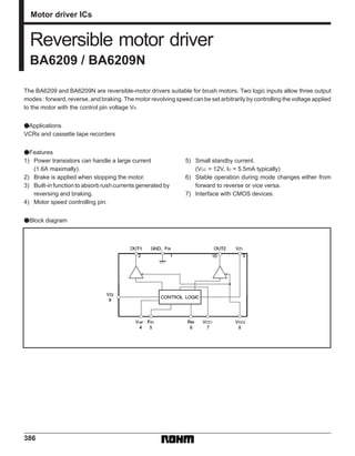
  • 1. 386 Motor driver ICs Reversible motor driver BA6209 / BA6209N The BA6209 and BA6209N are reversible-motor drivers suitable for brush motors. Two logic inputs allow three output modes : forward, reverse, and braking. The motor revolving speed can be set arbitrarily by controlling the voltage applied to the motor with the control pin voltage VR. FApplications VCRs and cassette tape recorders FFeatures 1) Power transistors can handle a large current (1.6A maximally). 2) Brake is applied when stopping the motor. 3) Built-in function to absorb rush currents generated by reversing and braking. 4) Motor speed controlling pin. 5) Small standby current. (VCC = 12V, IO = 5.5mA typically) 6) Stable operation during mode changes either from forward to reverse or vice versa. 7) Interface with CMOS devices. FBlock diagram
  • 2. 387 Motor driver ICs BA6209 / BA6209N FAbsolute maximum ratings (Ta = 25_C) FRecommended operating conditions (Ta = 25_C) FElectrical characteristics (unless otherwise noted, Ta = 25_C and VCC = 12V) FElectrical characteristic curves
  • 3. 388 Motor driver ICs BA6209 / BA6209N
  • 4. 389 Motor driver ICs BA6209 / BA6209N FMeasurement circuit
  • 5. 390 Motor driver ICs BA6209 / BA6209N FCircuit operation Input / output truth table Forward / reverse control, forced stop, and rush current absorption are controlled by the combination of FIN and RIN input states. (1) Forward / reverse control circuit When FIN is HIGH and RIN is LOW, current flows from OUT1 to OUT2. When FIN is LOW and RIN is HIGH, cur- rent flows from OUT2 to OUT1 (refer to the truth table). (2) Forced stop circuit By setting RIN and FIN both HIGH or both LOW, power supply to the motor is shut down and a brake is applied by absorbing the motor counter-electromotive force. (3) Rush current absorption circuit When a high voltage (caused by such as a motor rever- sal) is generated on OUT1 and OUT2, an internal comparator detects the high voltage and turns on an in- ternal circuit that absorbs rush currents. (4) Drive circuit The forward direction of the motor connected between OUT1 and OUT2 corresponds to the current flow from OUT1 to OUT2, and the reverse direction corresponds to the current flow from OUT2 to OUT1. The output voltage (VOUT) applied to the motor is given by the equation : VOUT (V) = VZD * VCE (sat.) = VZD * 0.2 (IOUT = 100mA) where VZD is the zener voltage of the constant voltage diode (ZD) connected to pin 4. If Vref is left OPEN, the output voltage (VOUT) is given by the equation : VOUT (V) = VCC1 * VCE (sat.) (PNP) * 2VF * VCE (sat.) = VCC1 * 1.8 (IOUT = 100mA) FPin descriptions
  • 6. 391 Motor driver ICs BA6209 / BA6209N FOperation notes (1) Resistor dividing IC power consumption To reduce power dissipated in the IC, a resistance (about 3X10Ω) must always be connected between VCC and the power supply pin of the driver circuit. If VCC2 is connected to VCC with no resistor, the IC can be damaged by over- current when operated at the voltage range close to the maximum operating voltage. (2) Control signal waveform The rise and fall times of signals applied to the control pins should be 5ms or less. Longer times can cause er- ratic operation of the internal logic circuits and may result in damage to the driver circuits. For example, if the supply voltage for the external control circuit comes up after the supply voltage of the IC, the ris- ing edge of the control signal slowly follows the rise of the externalsupply voltage. This could result in erratic opera- tion or damage to the IC due to excess currents. (3) IC ground voltage To provide separation between the circuit elements with- in the IC, the GND pin of the IC must always be held at a lower potential than the other pins. If the potential of the GND pin is allowed to rise above that of other pins (such as the control input pins), separation between the internal circuit elements could break down, resulting in erratic operation or internal damage. For example, a resistor may be connected between GND (pin 1) and the ground as shown in Fig. 19, when detect- ing and controlling the motor operating current. In this case, the potential of pin 1 would be above the ground po- tential by an amount equal to the voltage drop across the resistor. Therefore, dropping the input pin potential to the ground potential would have the effect of applying a neg- ative voltage to the input pin. This should be avoided by detecting the motor operating current in a way shown in Fig. 20. (4) Input pins Voltage should never be applied to the input pins when the VCC voltage is not applied to the IC. Similarly, when VCC is applied, the voltage on each input pin should be less than VCC and within the guaranteed range for the electrical characteristics. (5) Back-rush voltage Depending on the ambient conditions, environment, or motor characteristics, the back-rush voltage may fluctu- ate. Be sure to confirm that the back-rush voltage will not adversely affect the operation of the IC. (6) Large current line Largecurrents are carried by the motor power supply and motor ground for these ICs. Therefore, the layout of the pattern of the PC board and the constants of certain parameters for external compo- nents, such as the capacitor between the power supply and ground, may cause this large output current to flow back to the input pins, resulting in output oscillation or other malfunctions. To prevent this, make sure that the PC board layout and external circuit constants cause no problems with the characteristics of these ICs. (7) Power dissipation The power dissipation will fluctuate depending on the mounting conditions of the IC and the ambient environ- ment. Make sure to carefully check the thermal design of the application where these ICs sill be used. (8) Power consumption The power consumption by the IC varies widely with the power supply voltage and the output current. Give full consideration to the power dissipation rating and the thermal resistance data and transient thermal resistance data, to provide a thermal design so that none of the rat- ings for the IC are exceeded.
  • 7. 392 Motor driver ICs BA6209 / BA6209N (9) ASO Make sure that the output current and supply voltage do not exceed the ASO values. (10) Precautions for input mode switching To ensure reliability, it is recommended that the mode switching for the motor pass once through the open mode. (11) There are no circuits built into these ICs that pre- vent in-rush currents. Therefore, it is recommended to place a current limiting resistor or other physical counter- measure. (12) If the potential of the output pin sways greatly and goes below the potential of ground, the operation of the IC may malfunction or be adversely affected. In such a case, place a diode between the output and ground, or other measure, to prevent this. (13) The quality of these products have been carefully checked; however, use of the products with applied volt- ages, operating temperatures, or other parameters that exceed the absolute maximum rating given may result in the damage of the IC and the product it is used in. If the IC is damaged, the short mode and open modes cannot be specified, so if the IC is to be used in applications where parameters may exceed the absolute maximum ratings, then be sure to incorporate fuses, or other physi- cal safety measures.
  • 8. 393 Motor driver ICs BA6209 / BA6209N FApplication example FExternal dimensions (Units: mm)