
Recomendados
Más contenido relacionado
La actualidad más candente
La actualidad más candente (20)
Similar a Cd
Similar a Cd (20)
Más de mganguly123
Más de mganguly123 (20)
Cd
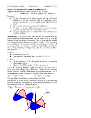
- 1. 03-871 Molecular Biophysics CD Spectroscopy September 25, 2009 Optical Rotary Dispersion and Circular Dichroism Suggested reading: Chapter 10 van Holde et al., pp. 465-496. : The Feynman Lectures on Physics. Vol 2, Chapter 32. Summary: • Circular dichroism (CD) arises because of the differential interaction of circularly polarized light with molecules which contain a chiral center or have coupled electric dipoles that are chiral. • CD is not observed unless an absorption band exists. • CD spectra of proteins and nucleic acids are much more sensitive to conformational changes than absorption spectra. • CD spectra of proteins can be used to obtain useful information on secondary structure. Introduction: Until now we have been studying the interaction of the transition electric dipole of molecules with the electric field of light. In addition to this interaction, the magnetic field of light can also interact with magnetic transition dipoles in molecules. In order for this interaction to be productive it is necessary that the molecule possess a center of asymmetry (such as α-carbons) or to have coupled electronic dipoles. These centers will interact with polarized light. The consequences of this interaction are: λ >> λABS: • Birefringence: (nL - nR) • Optical Rotary Dispersion (ORD): φ = 180 l (nL - nR)/ λ λ ≈ λABS: • Circular dichroism (CD) differential absorption of circularly polarized light: AL-AR • Ellipticity: θ = 2.303 (AL-AR) 180/ 4π or ∆ε = εL – εR Linear & Circularly Polarized Light: To understand how these effects occur when polarized light is passed through a sample we will decompose linearly polarized light into right and left circular-polarized light. For a wave propagating along the y axis (j), the electric field at the origin is: ˆ E r = k cos ωt + iˆ sin ωt ˆ ˆ E l = k cos ωt − i sin ωt The sum of these two fields gives linearly polarized light. For the case of Er the electric field vector will rotate in a right hand direction because the x-component of the electric field grows after t=0. In contrast El will rotate in a left hand direction. Figure 1: Generation of circular polarized light. Figure 1: Generation of circular-polarized light The optical activity of a molecule is due to a differential interaction of the molecule with right or left circularly polarized light. To help understand the origin of optical activity consider the following two 'molecules', which are mirror images of each other: Figure 1: Some "lock-washer" molecules 1
- 2. 03-871 Molecular Biophysics CD Spectroscopy September 25, 2009 Origin of Optical Activity: A flat molecule has no optical activity because it possesses a plane of symmetry. In contrast, the helical molecules shown below have optical activity. When a molecule is placed in an electric field the electrons involved in the transition will oscillate according to the direction of the electric field. In the case of the helical molecule they can be driven in a helical path. This generates a current loop in the helix and the current loop generates a magnetic dipole in the same way an electromagnet generates a magnetic field. The induced magnetic dipole is parallel with the z-component of the electric field that generated it. The induced magnetic dipole can interact with the magnetic component of the electric field. • No interaction is possible with the magnetic field associated from the z-component of the electric field. Why? • An interaction between the induced magnetic dipole and the electric field in the x-y plane is possible. Why? The phase of the electric field oscillation affects the coupling between the induced magnetic dipole and the magnetic field. For a productive interaction between the induced magnetic dipole and the magnetic field from the x-y electric vector the two fields must oscillate with the same phase. Only one direction of the circularly polarized light (right or left) will possess the correct phase, hence the reason why one of the components of the polarized light (Er or El) interacts more strongly with the chromophore. 2
- 3. 03-871 Molecular Biophysics CD Spectroscopy September 25, 2009 Circular Birefringence & Optical Rotary Dispersion (ORD) Optically active material will show a different refractive index for right and left circular polarized light. The index of refraction of a material is a consequence of the generation of an electric field by the dipoles within the material which oscillate due to the applied light. • At frequencies far removed from the absorption band the oscillations of the applied field induce oscillations of charges in the material which are in phase with the applied field. • As the frequency of the applied light approaches the absorption maximum there is an increasingly larger phase shift in the induced oscillations. • At higher frequencies, the induced oscillations change sign, reversing the effects seen at low frequencies. The oscillating electrons generate an electric field that contributes to the field of the transmitted light. The induced field generates a difference in refractive index for the two forms of light. The difference in refractive index is called circular birefringence: nl - nr Optical Rotary Dispersion (ORD) arises because of a difference in the index of refraction for left and right circularly polarized light. Due to the difference in refractive index the wavelength of the light for each direction of circularly polarized light is different while the light is in the media. Consequently, a phase shift will develop between the two circular components. This phase shift will cause a rotation of the linearly polarized light when it leaves the media. 180l (nl − nr ) φ= [degrees] λ The optical rotation as a function of wavelength is referred to the optical rotary dispersion. The ORD curve changes sign at the absorption maximum. This occurs because the phase of the oscillations of the electrons becomes 180 degrees out of phase from the incident light. This implies that the polarized light (right or left) which was retarded by the material at longer wavelength now becomes advanced with respect to the other polarized direction at shorter wavelengths. Circular Dichroism occurs as the wavelength of the incident light approaches that of the absorption band. In this case the oscillation of charges in the material is damped as energy is removed from the field by the absorption process. If the absorption is different for right and left handed circular-polarized light then the linearly polarized light will become elliptically polarized. The ellipticity (θ) of the light is defined by the arc tangent of the ratio of the major axis to the minor axis of the transmitted light. Usually, the actual absorption of each component of light is measured and the difference in absorption is called the circular dichroism (CD): CD = Al – Ar Which is related to the ellipticity by: 2.303( Al − Ar )180 θ= = 32.98 × ( Al − Ar ) 4π 3
- 4. 03-871 Molecular Biophysics CD Spectroscopy September 25, 2009 ER − EL tan θ = ER + EL I R/ 2 − I L/ 2 1 1 Small angle approximation. θ = 1/ 2 1/ 2 IR + IL I = I 0 e − A ln10 Beer’s law A=-log(I/Io) − AR − AL ∆A ln x = ln10 log10 x ln 10 ln 10 ln 10 e 2 −e 2 e 2 −1 θ= − AR − AL = ∆A + AL ln 10 ln10 ln10 ln 10 2 +1 Multiply by e e 2 +e 2 e 2 ∆A ln 10 ∆A e2 ≈1+ ln 10 2 Series expansion of ex ≈1 + x ∆A Apply series expansion ln 10 θ≈ 2 ∆A ln 10 + 2 2 ∆A Assume ∆A <<1 ln 10 θ≈ 2 2 Convert to degrees. ∆A 360 θ≈ ln 10 × 4 2π The molar ellipticity of the sample is given by: [θ ] = 100θ Cl Where C is the concentration in moles/liter and l is the path-length in cm, and θ is the measured ellipticity. The historical units of [θ] are deg cm2 dmole-1 instead of deg M-1 cm-1. Although these units seem odd, they can be easily derived: L mol 1000cm 3 mol deg M −1cm −1 = deg × cm −1 = deg × = deg100cm 2 dmol −1 mol 10dmol mol 10dmol The molar circular dichroism can also be related to the difference in the extinction coefficient for right and left circularly polarized light: θ = 32.98 × (ε l − ε r ) deg M −1cm [θ ] = 3,298∆ε = 3,298 (ε l − ε r ) deg cm2 dmol-1 It is becoming more common to express CD spectra in terms of the much more straight-forward difference in molar extinction coefficient: ∆ε = ε l − ε r 4
- 5. 03-871 Molecular Biophysics CD Spectroscopy September 25, 2009 Applications of Circular Dichroism: Determining Secondary Structure by CD: Various secondary structures have characteristic CD spectra (Figure 3). helix beta Figure 3: CD spectra of polypeptides (left) and CD spectra extracted from proteins. The scale on the left has been multiplied by 10-3, i.e. 80 = 80,000. Note that the CD spectrum (or optical activity) of α-helical residues is significantly greater than either random coil or β-sheet. This is a consequence of the interaction between transition dipoles oriented by the helical structure of peptide. This interaction is weaker in β-sheet and random coil. A similar interaction will also occur with nucleic acids (see below). The determination of secondary structure by CD is based on the fact that the CD spectra of a protein is well approximated by the CD of each peptide linkage: N θ λ = ∑θ iλ i =1 Where θiλ is the CD of a single peptide bond. There are three methods are currently used to determine the secondary structure of a protein from it's CD spectrum. Method 1: The simplest method is to use the CD spectra of polyamino acids. The CD spectrum of a protein can be taken to be the linear sum of the CD spectra from these various secondary structures: θ λ = fαθ λ + f βθ λβ + f cθ λc α Where fα are the fraction of the number of residues in the protein that are in an α-helical conformation. fβ is the fraction in the β-sheet, etc. The experimental data are fit to the reference spectra to determine the amounts of each secondary structure in the protein. A significant problem with this approach is that the model compounds are usually infinite in length, thus they do not mimic secondary structures in proteins, which are of finite 5
- 6. 03-871 Molecular Biophysics CD Spectroscopy September 25, 2009 length. In addition, the following problems also occur with any method of using CD to obtain secondary structure: • random coils are seldom random • Phe, Tyr, His, and Trp can contribute to peptide CD spectra • Left handed helical structures can occur • Disulfide bonds are very active • Prosthetic groups are also very active Method 2: A more reliable approach is to use proteins of known structure (and CD spectra) to define the basis set. For each of the known proteins the following is assumed: 3 θ λ = ∑ χ jθ λj j =1 For each of the known proteins, the fractions of residues in various secondary structures are known ( e.g. χ α ). From these data it is possible to obtain basis spectra for the three types of secondary structure. These basis spectra should now reflect the influence of the protein structure of the CD spectra of residues in various secondary structures. As with the first method, the CD spectra of the unknown protein is the weighted sum of the reference CD spectra: θ λ = fαθ λ + f βθ λβ + f cθ λc α The hope here is that the new reference spectra will be 'more accurate' than those based on homo-polymers. A flaw in the above approach is the assumption that there are only three classes of secondary structure and that each class has a unique CD spectrum. Method 3 [Hennessey & Johnson, Biochemistry, 20, 1085.]: A more unbiased method of approaching this problem is to extract, using mathematical methods, a generalized basis set from the CD spectra of proteins with known structures without regard to the actual secondary structure of the protein. That is, we now assume the CD spectra of a protein is: N θ λ = ∑ aiθ λi i Where N are the total number of basis spectra, ai is the weight of the ith spectra to the total CD and θλi is the CD of the ith basis spectra at λ. Determining the basis spectra and the coefficients, ai is accomplished by a general technique called singular value decomposition. SVD: Singular Value Decomposition: This is a general mathematical technique that can be used to extract out the principle components of a complex mixture of different spectra. Principle components are analogous to the three basis vectors that can be used to define any vector in a three- dimensional space. 6
- 7. 03-871 Molecular Biophysics CD Spectroscopy September 25, 2009 SVD can be used in many different situations. As an example, say CD spectra (or IR spectra, or UV-Vis spectra...) were acquired at 3 different ligand concentrations and at five different wavelengths and we wanted to extract out the 'part' of the spectra that was affected by ligand binding. The raw experimental data can be written in matrix form (each column represents a different ligand concentration): aλ 1 aλ 1 aλ 1 a aλ 2 aλ 2 λ2 A = aλ 3 aλ 3 aλ 3 aλ 4 aλ 4 aλ 4 aλ 5 aλ 5 aλ 5 This matrix can be decomposed into a product of three matrices: A = USV T U: The columns of this matrix are the 'basis spectra', ui. A weighted linear sum of these spectra can be used to generate the original raw data. u1 1 λ 2 uλ 1 uλ1 3 1 2 3 uλ 2 uλ 2 uλ 2 U = uλ 3 1 2 uλ 3 uλ 3 3 1 2 3 uλ 4 uλ 4 uλ 4 u1 2 uλ 5 uλ 5 3 λ5 S: This is a diagonal matrix: s1 0 0 S = 0 s2 0 0 0 s3 Each entry in this matrix is associated with a basis spectrum in the U matrix (e.g. s2 is associated with u2. The size of each si determines the importance, or size of contribution, of this basis to the experimental data. This can be seen by taking the product of U and S: uλ 1 u λ 1 1 2 uλ 1 3 s1uλ1 1 2 s 2 uλ 1 s3uλ1 3 1 3 1 3 2 uλ 2 uλ 2 uλ 2 s1 0 0 s1uλ 2 2 s 2 uλ 2 s3uλ 2 U × S = uλ 3 u λ 3 0 = s1uλ 3 1 2 uλ 3 × 0 3 s2 1 2 s 2 uλ 3 s3uλ 3 3 1 3 3 2 uλ 4 uλ 4 uλ 4 0 0 s3 s1uλ 4 1 2 s 2 uλ 4 s3uλ 4 u1 u 2 3 uλ 5 s u1 2 s 2 uλ 5 s3uλ 5 3 λ5 λ5 1 λ5 VT Is a square matrix, each entry gives the contribution of each basis vector to the signal at a particular wavelength: s1uλ1 1 s2uλ12 s3uλ1 3 1 3 s1uλ 2 2 s 2 uλ 2 s3uλ 2 V11 V12 V13 U × S × V = s1uλ 3 s3uλ 3 × V21 V22 V23 T 1 2 3 s 2 uλ 3 1 3 s1uλ 4 2 s 2 uλ 4 s3uλ 4 V31 V32 V33 s u1 2 s2uλ 5 3 s3uλ 5 1 λ5 7
- 8. 03-871 Molecular Biophysics CD Spectroscopy September 25, 2009 For example, the measured spectra at λ1 for the 2nd ligand concentration is: • A C2 = s1uλ1V12 + s2uλ1V22 + s3uλ1V33 λ1 1 2 31 Figure 4: Basis sets used to fit CD data (left). Fit to CD spectrum of papain (right). SVD of Protein CD spectra: Determining Secondary Structure by SVD: We would like to obtain the secondary structure of a protein from its CD spectrum. In matrix form, this relationship is: F= XA where F is a vector that is the fraction of each secondary structure, A is the CD spectrum of the unknown protein, and X relates the two. Since we know from SVD that there are only five significant components to the CD spectrum of a protein we will assume that we can represent a protein in terms of five secondary structures: 8
- 9. 03-871 Molecular Biophysics CD Spectroscopy September 25, 2009 θ λ 1 f H X 11 . . . . . f θλ 2 ⊥β . . . . . . θ λ3 f||β = . . . . . . × θλ4 fT . . . . . . θ λ 5 fO . . . . . . θ λ 6 If we can determine X, then the fraction of each secondary structure for an unknown protein can be found. If we begin with a large set of proteins with known secondary structure (F) and CD spectra (A) we can obtain X, using SVD. For a set of 3 proteins and CD data collected at six wavelengths, the matrices would look like: f1 θ 1 θ 2 θ 3 fH 2 fH X 3 . . . . . λ 1 λ1 λ1 3 H 1 3 11 1 2 2 f⊥ β f⊥ β f ⊥ β . . . . . . θ λ 2 θ λ 2 θ λ 2 1 2 3 θ 1 θ 2 θ 3 f ||β f f = . . . . . . × λ 31 λ3 2 λ3 3 || β ||β θ θλ 4 θ λ 4 1 3 . . . . . . λ 4 θ 1 θλ 5 θ λ 5 2 fT fT fT 2 3 fO 1 2 3 . . . . . . λ 5 fO fO 1 2 3 θ λ 6 θ λ 6 θ λ 6 For this set of known proteins: F = XA = X (USV T ) , where A has been subject to SVD, i.e. A=USVT X can be solved by multiplying F by V, S-1, and U: F × V × S −1 × U T = X (USV T ) × V × S −1 × U T = X (US ) × S −1 × U T = X (U ) × U T = X Note: U×UT = 1 since all U vectors are orthonormal. V×VT = 1 from the theory of SVD. 1 / s 0 S × S-1 =1 if we define S-1 = 1 0 1 / s2 Secondary Structure of Membrane Proteins: CD can also be used to determine the secondary structure of membrane proteins (or other aggregated systems). However, the analysis is far from simple. Two optical effects occur in suspensions of particles which distort CD spectra. First, the overall absorption of the system decreases because proteins in the particle can be "shaded" by others in the same particle. Second, the scattering of right and left circularly polarized light is not equal. The former problem affects the overall amplitude of the spectrum, while the latter affects the shape of the CD Figure 5: Effect of particle size on CD Spectrum spectrum. These effects can be corrected to produce rather 9
- 10. 03-871 Molecular Biophysics CD Spectroscopy September 25, 2009 reasonable CD spectra of membrane bound proteins. However, it is clear that IR is the preferred technique for obtaining information on the secondary structure membrane proteins. Other Application of CD Spectroscopy to Proteins. CD can also be used in an empirical manner to determine protein unfolding, ligand binding, etc. CD is much more sensitive to changes in secondary structure than absorption spectroscopy and is thus an excellent method of following protein denaturation. Application of CD to Nucleic acids: The major application of CD to the study of nucleic acids is to determine the degree of base stacking. The CD of a dimer is very dependent on the interaction of the monomers. For example: poly C has the following spectral properties: Solvent Ellipticity A260 Water 35,000 1.0 Ethylene glycol 7,000 1.3 In this case both the CD and the hyper-chromicity show that polyC is a helix in water and that this helix is due to base stacking. DNA-Protein Interactions: Since proteins have weak CD bands at 250nm, CD is well suited for following protein induced changes in nucleic acid structure. These changes can be convenient for monitoring binding of proteins to nucleic acids. 10