Hazardous Area Pressure Switch

Applications oil industry: Wellhead control panels, chemical injection skids, hydraulic control packages, gas compression skids, offshore and onshore. Highly reliable devices utilizing the Custom Control Sensors Dual-Snap® Belleville disc spring principle. Turck® electrical connection for easy “plug and play” in Class I, Division 2 applications. Turck® connector provides superior ingress protection. Hermetically sealed electrical assembly for environmental protection. No electrical junction box required.Rigid, compact and internally adjustable for convenient field set point adjustment. Repeatable and stable set points. Vibration and shock resistant. High cycle life. High over-pressure capability. Various options for wetted materials and electrical ratings to meet a wide range of application requirements and media compatibility.

Recomendados
Recomendados
Más contenido relacionado
La actualidad más candente
La actualidad más candente (20)
Destacado
Similar a Hazardous Area Pressure Switch
Similar a Hazardous Area Pressure Switch (20)
Más de Mountain States Engineering and Controls
Más de Mountain States Engineering and Controls (20)
Último
Último (20)
Hazardous Area Pressure Switch
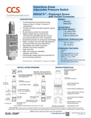
- 1. Hazardous Areas Adjustable Pressure Switch 6900GE*K** - Diaphragm Sensor with Turck® Connector DESCRIPTION • Turck® electrical connection for easy “plug and play” in Class I, Division 2 applications • Turck® connector provides superior ingress protection • No electrical junction box required. • Highly reliable devices utilizing the CCS Dual-Snap® Belleville disc spring principle pioneered by CCS’ engineers. • Engineering based on aerospace technology. • Rigid, compact and internally adjustable for convenient field set point adjustment. • Repeatable and stable set points. • Vibration and shock resistant. • High cycle life. • High over-pressure capability. (System and Proof) • Hermetically sealed electrical assembly for environmental protection. SHIPPING WEIGHT: APPROXIMATELY 18 OUNCES (510 GRAMS) ADJUSTMENT WHEEL 1.00 HEX 7/8-16 UN MALE THREADS 4 OR 6 MALE PINS UL & cUL CERTIFIED PRODUCT 6.75 MAX (171,45 mm) ELECTRICAL CONNECTION PRESSURE PORT 1/4-18 NPT 1.75 MAX (44,5 mm) .75 (19,0 mm) 1.25 HEX (31,8 mm) (2) MOUNTING HOLES .210 (5,3 mm) DIAMETER 1.34 (34,0 mm) 1.50 1.125 (28,6 mm) (38,1 mm) (25,4 mm) PRESSURE PORT 1-11-1/2 NPT 1.375 HEX (34,9 mm) 2.41 (61,2 mm) 7.75 MAX (195,85 mm) DIAPHRAGM IS FLUSH WITH THIS SURFACE 6900GZEK**-7066 FLUSH MOUNT CONFIGURATION SHOWN BELOW (-7074 FLUSH MOUNT HASTELLOY) INSTALLATION DRAWING Models: 6900GE*K**, Page 1 of 2 Form 830G, 3.4.15 DESIGN PRINCIPLES ccsdualsnap.com SERIES: 6900GE* 6900GZE* ADJUSTABLE SET POINT RANGE: 1 to 3400 PSIG 0.07 to 234 bar 6.89 to 23400 kPa OPERATING TEMPERATURE: Temperature limits change with O-ring selection. -40° to 176°F -40° to 80°C STANDARD FEATURES: • CE Mark • CRN • Dual Seal: ANSI/ISA-12.27.01 • NACE MR0175 / ISO 15156 • NEMA: 4, 7, 9,13 / IP66 • U.L. / cUL • Hermetically Sealed Electrical Assembly • 316 SST Electrical Assembly FIELD SETTING: Loosen access cover. Adjust adjustment screw using screwdriver slot as illustrated, then attach to a variable pressure source with a suitable gage, and check that the circuit continuity operates at the pressures desired. Clockwise to increase settings. Counterclockwise to decrease setting. NOTE: DO NOT USE ELECTRICAL HEX FOR TORQUING. *See Installation & Maintenance Instructions 10-1228
- 2. OPERATING AND ORDERING DATA SERIES 6900GE*K** WETTED PARTS: 1/4"-18 NPT ALUMINUM PRESSURE PORT, POLYIMIDE DIAPHRAGM, BUNA N O-RING ADJUSTABLE SET POINT RANGE APPROX. DEAD BAND PSI (BAR) SYSTEM PRESSURE PSIG (BAR) PROOF PRESSURE PSIG (BAR) INCREASING PRESSURE PSIG (BAR) DECREASING PRESSURE PSIG (BAR) 6900GE*K**12 3-20 (0.21-1.4) 1-18 (0.07-1.2) 2 (0.14) 500 (34.5) 750 (51.7) 6900GE*K**14 6-75 (0.41-5.1) 2-71 (0.14-4.9) 4 (0.28) 6900GE*K**16 12-150 (0.8-10.3) 4-142 (0.28-9.8) 8 (0.6) 1500 (103) 2000 (138) 6900GE*K**18 30-375 (2.0-25.9) 10-355 (0.7-24.4) 20 (1.4) 6900GE*K**20 300-1000 (20.7-69) 250-950 (17.2-66) 50 (3.5) 2000 (138) 3000 (207) 6900GE*K**22 700-2200 (48.3-152) 600-2100 (41.4-145) 100 (6.9) 3000 (207) 4500 (310) 6900GE*K**24 1800-3400 (124-234) 1580-3180 (109-219) 220 (15.2) 5000 (345) 7500 (517) SERIES 6900GZE*K** WETTED PARTS: 1/2"-14 NPT 316 STAINLESS STEEL PRESSURE PORT & DIAPHRAGM, VITON O-RING ADJUSTABLE SET POINT RANGE APPROX. DEAD BAND PSI (BAR) SYSTEM PRESSURE PSIG (BAR) PROOF PRESSURE PSIG (BAR) INCREASING PRESSURE PSIG (BAR) DECREASING PRESSURE PSIG (BAR) 6900GZE*K**12 3-20 (0.21-1.4) 1-18 (0.07-1.2) 2 (0.14) 500 (34.5) 750 (51.7) 6900GZE*K**14 9-75 (0.6-5.1) 3-69 (0.21-4.8) 6 (0.41) 6900GZE*K**16 18-150 (1.2-10.3) 6-138 (0.41-9.5) 12 (0.8) 1500 (103) 2000 (138) 6900GZE*K**18 45-375 (3.1-25.9) 15-345 (1.0-23.8) 30 (2.0) 6900GZE*K**20 300-1000 (20.7-69) 225-925 (15.5-64) 75 (5.1) 2000 (138) 3000 (207) 6900GZE*K**22 700-2200 (48.3-152) 520-2020 (35.9-139) 180 (12.4) 3000 (207) 4500 (310) 6900GZE*K**24 1800-3400 (124-234) 1520-3120 (105-215) 280 (19.3) 5000 (345) 7500 (517) SERIES 6900GZE*K**-7066 FLUSH MOUNT WETTED PARTS: 1” 316 STAINLESS STEEL PRESSURE PORT & WELDED DIAPHRAGM ADJUSTABLE SET POINT RANGE APPROX. DEAD BAND PSI (BAR) SYSTEM PRESSURE PSIG (BAR) PROOF PRESSURE PSIG (BAR) INCREASING PRESSURE PSIG (BAR) DECREASING PRESSURE PSIG (BAR) 6900GZE*K**12-7066 3-15 (0.21-1.0) 1-13 (0.07-0.9) 2 (0.14) 500 (34.5) 750 (52) 6900GZE*K**14-7066 12-75 (0.83-5.1) 6-69 (0.41-4.8) 6 (0.41) 6900GZE*K**16-7066 18-150 (1.2-10.3) 6-138 (0.41-9.5) 12 (0.8) 1500 (103) 2000 (138) 6900GZE*K**18-7066 45-375 (3.1-25.9) 15-345 (1.0-23.8) 30 (2.0) 6900GZE*K**20-7066 300-1000 (20.7-69) 225-925 (15.5-64) 75 (5.1) 2000 (138) 3000 (207) 6900GZE*K**22-7066 700-2200 (48.3-152) 520-2020 (35.9-139) 180 (12.4) 3000 (207) 4500 (310) OPTIONAL STANDARD MODIFIED SUFFIXES 7008: Gold Contacts 7042: Stainless Steel Body 7044: Monel Port and Diaphragm 7045: Hastelloy C-276 Port and Diaphragm 7074: 1” Flush Mount Hastelloy C-276 Port & Welded Diaphragm 7082: 316 SST Port, Piston & Body, E.N.P. Front cover & Locks. 1/4-18 NPT Female Pressure port. 7088: 1/4" -18 NPT Female 316 Stainless Steel Pressure Port 7089: 1/2" -14 NPT Male 316 Stainless Steel Pressure Port ELECTRICAL CHARACTERISTICS RATING OF SWITCH ELEMENT SCHEMATIC AND WIRING CODE (**) SPST SPDT DPST Res. Res. Res. 30 DC *30 DC VOLTS AMPERES *Gold Contacts -7008 Suffix 600 mA 600 mA HOW TO ORDER Follow these steps to build your part number: 1. Specify the series based on your required set point, range, dead band, system pressure and proof pressure. 2. Add desired options model code letter (*). 3. Add required wiring code (**=4O, 6O, 4D, 4C). 4. Add the applicable standard suffix number. (Ex: 6900GCEK4D12-7044) PRESSURE CONVERSION 1 BAR = 14.5 PSI 1 kPa = 0.145 PSI ccsdualsnap.com Models: 6900GE*K**, Page 2 of 2 Form 830G, 3.4.15 Note: Additional modified standard suffixes are available, consult CCS sales department or CCS Representative. CERTIFICATIONS Consult CCS website for complete certification and approval listing. OPTIONS MODEL CODES (*) A: Viton® O-Ring (STD on GZE models) C: + Suffix for Different Welded Capsule Materials F: Ethylene Propylene O-Ring ELECTRICAL ENCLOSURE CERTIFICATIONS * UL Laboratories Inc. Listed (File E32961) for hazardous locations. * Field device rated for: Class I, Division 2, Groups A, B, C or D. * See Hazardous Location - Installation Drawing Field Device CCS-ENG NI - 2.404 Hazardous Areas Adjustable Pressure Switch 6900GE*K** - Diaphragm Sensor with Turck® Connector