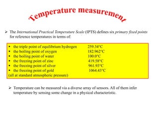
SlideShare una empresa de Scribd logo
1 de 41
 The International Practical Temperature Scale (IPTS) defines six primary fixed points
for reference temperatures in terms of:
 the triple point of equilibrium hydrogen 259.34°C
 the boiling point of oxygen 182.962°C
 the boiling point of water 100.0°C
 the freezing point of zinc 419.58°C
 the freezing point of silver 961.93°C
 the freezing point of gold 1064.43°C
(all at standard atmospheric pressure)
 Temperature can be measured via a diverse array of sensors. All of them infer
temperature by sensing some change in a physical characteristic.
The various temperature measuring devices can be classified as :
Mechanical Methods
1. Expansion of solids
(a) Solid rod thermometer
(b) Bimetallic thermometer
2. Expansion of liquids
(a) Liquid-in- glass thermometer
(b) Liquid-in- metal thermometer
3. Expansion of gases
(a) Gas thermometers
Electrical Methods
1. Electrical resistance thermometers
2. Thermistors
3. Thermocouples and thermopiles
Based on Radiation Properties
1. Total radiation pyrometer
2. Optical pyrometer
3. Infra-red pyrometer
Mechanical Methods
1. Expansion of solids
(a) Solid rod thermometer
The change ( Δ l) of the original length l of a solid due to change in temperature Δ t is
given by ,
Δ l = l α Δ t
Where, α is the coefficient of linear expansion usually taken as a constant over a
particular temperature range for a metal.
(b) Bimetal thermometer
 Bimetal thermometers are employed usually in the – 30oC to 550 oC temperature
range
 Two dissimilar metals are bonded together into what is called a bimetallic strip.
 Suppose metal A has a smaller coefficient of thermal expansion than does metal B. As
temperature increases, metal B expands more than does metal A, causing the bimetallic
strip to curl upwards as sketched.
 One common application of bimetallic strips is in home thermostats, where a bimetallic
strip is used as the arm of a switch between electrical contacts. As the room temperature
changes, the bimetallic strip bends as discussed above. When the bimetallic strip bends
far enough, it makes contact with electrical leads that turn the heat or air conditioning on
or off.
 Another application is in circuit breakers (the bimetallic strip is labeled “5” in the photo
to the right). High temperature indicates over-current, which shuts off the circuit [from
Wikipedia].
 Another common application is for use as oven, wood burner, or gas grill thermometers.
These thermometers consist of a bimetallic strip wound up in a spiral, attached to a dial
that is calibrated into a temperature scale.
2. Expansion of liquids
(a) Liquid-in- glass thermometer
(b) Liquid-in- metal thermometer
(a) Liquid-in- glass thermometer
 The most common and well-known thermometer is the liquid-in-glass
thermometer.
 As the temperature rises, the liquid expands, moving up the tube. The scale is
calibrated to read temperature directly.
 Usually, mercury or some kind of alcohol is used for the liquid.
 Pressure thermometer
 A pressure thermometer operates by the expansion of a gas instead of a liquid or solid.
(Note: There are also pressure thermometers that use a liquid instead of a gas.)
 Suppose the gas inside the bulb and tube can be considered an ideal gas. The ideal gas
law is PV = mRT, where P is the pressure, V is the volume, and m is the mass of the gas.
R is the gas constant for the specific gas (not the universal gas constant), and T is the
absolute temperature of the gas.
 o Specific gas constant R is a constant. The bulb and tube are of constant volume, so V
is a constant. Also, the mass m of gas in the sealed bulb and tube must be constant
(conservation of mass). Hence, the ideal gas equation reduces to P= constant T.
 A pressure thermometer therefore measures temperature indirectly by measuring
pressure.
 The gage is a pressure gage, but is typically calibrated in units of temperature instead.
 A common application of this type of thermometer is measurement of outside
temperature from the inside of a building. The bulb is placed outside, with the tube
running through the wall into the inside.
 The gage is on the inside. As T increases outside, the bulb temperature causes a
corresponding increase in pressure, which is read as a temperature increase on the
gage.
Electrical Methods
1. Electrical resistance thermometers
2. Thermistors
3. Thermocouples and thermopiles
Electrical Methods
Electrical
Methods
Thermoresistive or
Variable Resistance
Transducers
Thermistors
Resistance
temperature
detector
(RTD)
Thermo-electric or
e.m.f. generating
transducers
 The change of resistance with temperature in case of some materials forms the basis
of temperature measurement.
 These materials fall into two categories : one using conductors (metals) and other
semi-conductors.
 The resistance of highly conducting materials (generally metals) increases with
temperature. Examples are nickel, copper, platinum, tungsten and silver.
 A temperature measuring device using an element of this type is resistance thermometers
or resistance temperature detector (RTD). Whereas, the resistance of semiconductors
generally decreases with increase of temperature and are called thermistors.
Resistance temperature detectors
 A resistance temperature detector (abbreviated RTD) is basically either a long, small
diameter metal wire (usually platinum) wound in a coil or an etched grid on a substrate,
 The resistance of an RTD increases with increasing temperature.
 In general, the resistance –temperature relationship for most metals over a wide
range :of temperature is given by the following empirical relation
R = R0( 1 + AT + BT2)
Where, R = resistance at absolute temperature T
R0 = resistance at the reference temperature
A, B = constants for the material
 Over a limited temperature range around 0oC (273 K) the following relationship
can be used :
Rt = Ro (1 + α t)
Where, α = the temperature coefficient of resistance of material in oC-1
Ro = resistance at 0oC
t = temperature relative to
If a change in temperature from t1 to t2 is considered, then ,
R1 = Ro (1 + α t1)
R2 = Ro (1 + α t2)
Rearrangement gives :
𝑡2 = 𝑡1 +
𝑅2 − 𝑅2
𝛼𝑅 𝑜
 A thermistor is similar to an RTD, but a semiconductor material is used instead of a
metal. A thermistor is a solid state device.
Thermistors
 A thermistor has larger sensitivity than does an RTD, but the resistance change
with temperature is nonlinear, and therefore temperature must be calibrated with
respect to resistance.
 Thermistors are labeled by their resistance at 25oC. For example, two popular
thermistors are type 2252 (2252 Ω at 25oC) and type 5000 (5000 Ω at 25oC)
 The upper temperature limit of thermistors
is typically lower than that of RTDs. In fact,
the maximum temperature of operation is
sometimes only 100oC to 200oC for a typical
commercial thermistor. However,
thermistors have greater sensitivity and are
typically more accurate than RTDs or
thermocouples.
 Thermistors usually have negative temperature coefficient, their resistance decreases as
the temperature increases.
Thermoelectric effect sensors (thermocouples)
 Thermoelectric effect sensors rely on the physical principle that, when any two
different metals are connected together, an e.m.f., which is a function of the
temperature, is generated at the junction between the metals. The general form of this
relationship is:
e = a1T + a2T2 + a3T3 + ……..+anTn
where e is the e.m.f. generated and T is the absolute temperature.
 This is clearly non-linear, which is inconvenient for measurement applications.
Fortunately, for certain pairs of materials, the terms involving squared and higher
powers of T (a2T2 + a3T3 etc.) are approximately zero and the e.m.f.–temperature
relationship is approximately linear according to:
e ≈ a1T
 Wires of such pairs of materials are connected together at one end, and in this
form are known as thermocouples.
 Thermocouples are manufactured from various combinations of the base metals copper and
iron, the base-metal alloys of alumel (Ni/Mn/Al/Si), chromel (Ni/Cr), constantan (Cu/Ni),
nicrosil (Ni/Cr/Si) and nisil (Ni/Si/Mn), the noble metals platinum and tungsten, and the
noble-metal alloys of platinum/rhodium and tungsten/rhenium.
 Only certain combinations of these are used as thermocouples and each standard
combination is known by an internationally recognized type letter, for instance type K
is chromel–alumel.
 The e.m.f.–temperature characteristics for some of these standard thermocouples are
shown in Figure 14.1: these show reasonable linearity over at least part of their
temperature-measuring ranges.
 A typical thermocouple, made from one chromel wire and one constantan(a copper–
nickel alloy) wire, is shown in Figure(a). For analysis purposes, it is useful to
represent the thermocouple by its equivalent electrical circuit, shown in Figure (b).
The e.m.f. generated at the point where the different wires are connected together is
represented by a voltage source, E1, and the point is known as the hot junction.
 The e.m.f. generated at the hot junction is measured at the open ends of the
thermocouple, which is known as the reference junction.
 To save money of using wire to many centimeters, extension leads up to several metres
long are normally connected between the thermocouple and the measuring instrument.
This modifies the equivalent circuit to that shown in Figure (a).
 There are now three junctions in the system and consequently three voltage sources, E1,
E2 and E3, with the point of measurement of the e.m.f. (still called the reference
junction) being moved to the open ends of the extension leads.
 The measuring system is completed by connecting the extension leads to the voltage
measuring instrument. As the connection leads will normally be of different materials
to those of the thermocouple extension leads, this introduces two further e.m.f.-
generating junctions E4 and E5 into the system as shown in Figure (b). The net output
e.m.f. measured (Em) is then given by:
Em = E1 + E2 + E3 + E4 + E5
and this can be re-expressed in terms of E1 as:
E1 = Em - E2 - E3- E4 - E5
 It is usual to choose materials for the extension lead wires such that the magnitudes of
E2 and E3 are approximately zero, irrespective of the junction temperature.
 A zero junction e.m.f. is most easily achieved by choosing the extension leads to be of
the same basic materials as the thermocouple, but where their cost per unit length is
greatly reduced by manufacturing them to a lower specification.
 However, such a solution is still prohibitively expensive in the case of noble metal
thermocouples, and it is necessary in this case to search for base-metal extension leads
that have a similar thermoelectric behaviour to the noble-metal thermocouple.
In this form, the extension leads are usually known as compensating leads.
 A typical example of this is the use of nickel/copper–copper extension leads connected to
a platinum/rhodium–platinum thermocouple. Copper compensating leads are also
sometimes used with some types of base metal thermocouples and, in such cases, the law
of intermediate metals can be applied to compensate for the e.m.f. at the junction between
the thermocouple and compensating leads.
Example 1
If the e.m.f. output measured from a chromel–constantan thermocouple is 13.419mV
with the reference junction at 0°C, the appropriate column in the tables shows that this
corresponds to a hot junction temperature of 200°C.
Example 2
If the measured output e.m.f. for a chromel–constantan thermocouple (reference
junction at 0°C) was 10.65 mV, it is necessary to carry out linear interpolation between
thetemperature of 160°C corresponding to an e.m.f. of 10.501mV shown in the tables
and the temperature of 170°C corresponding to an e.m.f. of 11.222 mV. This
interpolationprocedure gives an indicated hot junction temperature of 162°C.
Thermocouple types
 The five standard base-metal thermocouples are:
chromel–constantan (type E),
iron–constantan (type J),
chromel–alumel (type K),
nicrosil–nisil (type N)
copper–constantan (type T).
 Chromel–constantan devices give the highest measurement sensitivity of 80 μV/°C,
with an inaccuracy of š0.5% and a useful measuring range of 200°C up to 900°C.
 Iron–constantan thermocouples have a sensitivity of 60 μV/°C and are the preferred
type for general-purpose measurements in the temperature range 150°C to °C1000°C,
where the typical measurement inaccuracy is ±0.75%.
 Thermocouples made from platinum and a platinum–rhodium alloy (type R and type
S) have a low inaccuracy of only ± 0.5% and can measure temperatures up to
1500°C, but their measurement sensitivity is only 10 μV/°C.
 Alternative devices made from tungsten and a tungsten/rhenium alloy have a better
sensitivity of 20 μV/°C and can measure temperatures up to 2300°C.
 Thermocouple manufacturers have standardized the use of certain pairs of metals
for thermocouples.
 Each standard thermocouple has been assigned both a letter and a color. For
example, type J and type T thermocouples are used in our ME 345 lab.
Standard thermocouples
 A type J thermocouple has the color black, and uses iron and constantan as its
component metals. (Constantan is an alloy of ≈ 45% nickel and ≈ 55% copper.)
 A type T thermocouple has the color blue, and uses copper and constantan as its
component metals.
 A type K thermocouple has the color yellow, and uses chromel and alumel as its
component metals. (Chromel is an alloy of ≈ 10% chromium and ≈ 90% nickel.)
Type K thermocouples are the most popular variety in use today. In fact, many
digital multimeters (DMMs) can measure temperature by plugging in a type K
thermocouple with standard connections.
 By convention, the reference temperature for thermocouple tables is 0oC. Hence, all
thermocouple voltages are given relative to 0oC – the voltage at 0oC is listed as zero
volts.
 If you wire the thermocouple according to one of the above diagrams with TR = 0oC,
the thermocouple voltage at any sensing temperature should match with that listed in
the tables.
Quartz crystal thermometer
 It is based on the principle that the resonant frequency of a quartz crystal is a function of
temperature
 The normal operating range of a quartz crystal thermometer is – 40oC to 230oC with a
resolution of 0.1oC.
Thermocouple Laws
First some notation:
 Let T1 be the temperature of bath 1, and T2 be the temperature of bath 2.
 Let V1-Rbe defined as the voltage produced by a thermocouple at temperature T1
when a proper reference junction at temperature TR is used (TR = reference
temperature = 0oC). Note that V1-R is the voltage listed
in the thermocouple tables at temperature T1.
 Let V1-2be defined as the difference in voltage between V1-Rand V2-R, namely,
V1-2= V1-R - V2-R.
Law of intermediate metals
 What is a total radiation pyrometer? What are its advantages and disadvantages?
 A pyrometer is used to measure the temperature of an object from a distance,
without making contact.
 The method used for making these non-contacting temperature measurements is
known as radiation pyrometry. Non-contact temperature sensors use the concept of
infrared radiant energy to measure the temperature of objects from a distance.
 After determining the wavelength of the energy being emitted by an object, the
sensor can use integrated equations that take into account the body's material and
surface qualities to determine its temperature. You can read
 The benefit of a radiation pyrometer is there is no need for direct contact with
what you are measuring the temperature of. These pyrometers come in handy
when the object is moving, as on an assembly line; when it is very hot, as inside
a furnace; or when it is inaccessible, as inside a high-vacuum chamber.
Radiation Methods (Pyrometry)
 Under the following situations , the radiation method should be used :
1. The body is too hot and a contact may damage or melt the device or thermometer.
2. The body is not accessible for actual physical contact as it may be moving or is too far
off.
3. When temperature distribution over the surface of the body to be determined.
 All bodies above absolute zero temperature radiate energy.
 Heat radiations emitted from the body above temperatures 650oC are of
sufficient intensity and are used for temperature measurements.
 The instruments based on sampling and measuring radiant energy from the hot
body re called pyrometrys.
 There are three types of pyrometrys :
1. Total radiation pyrometrys.
2. Optical pyrometrys.
3. Infrared pyrometrys.
o Radiative properties of an object change with temperature.
o So, radiative properties are measured to infer the temperature of the object.
Principle of operation:
o The advantages of radiative pyrometry are:
 There is no physical contact with the object whose temperature is being
measured.
 Very high temperatures can be measured.
 A pyrometer is any temperature-measuring device that includes a sensorand a readout.
However, in this section we will discuss only radiationtypepyrometers. A radiation
pyrometer is a noncontact temperaturesensor that infers the temperature of an object by
detecting its naturallyemitted thermal radiation. An optical system collects the visible
and infraredenergy from an object and focuses it on a detector, as shown inFigure 7-21.
The detector converts the collected energy into an electricalsignal to drive a temperature
display or control unit.
Total Radiation Pyrometry :
 Objects radiate electromagnetic energy. The higher the temperature of an object the
more electromagnetic radiation it emits. This radiation occurs within the infrared
portion of the electromagnetic spectrum (see Figure 3-11).
Infrared
 Infrared temperature sensors work by measuring the amount of infrared energy emitted by
an object, allowing us to measure the temperature of an object without being in contact.
 Ideal black body is the basis of infrared temperature measurement and gives rise to the
emittance setting.
 The emittance of a real surface is the ratio of the thermal radiation emitted by the
surface at a given temperature to that of the ideal black body at the same temperature.
 Emittance is a decimal number that ranges between 0 and 1 or a percentage between 0%
and 100%.
o An infrared pyrometer infers the temperature of a hot surface by measuring the
temperature of a detector inside a detector chamber as sketched to the right.
o The detector itself is usually a thermopile. It measures Tdet, the temperature of the
detector inside the chamber.
o Tind is the indicated temperature, which is calculated from Tdet, from the known
geometry and the radiation equations. Tind is calibrated as a function of TH for a body of
some assumed emissivity εassumed, typically 0.95 or so.
o The instrument is set up such that Tind is a function of the voltage output, and the
display typically indicates temperature Tind rather than voltage Vdet.
o Tind can be thought of as an uncorrected estimate of TH, since the emissivity of the
object may not be the same as that assumed by the infrared pyrometer. In other
words, if the actual emissivity of the object is not the same as the assumed
emissivity, Tind is incorrect.
o Optical pyrometer
o An optical pyrometer is useful for measuring very high temperatures of things that
glow (even flames).
o It consists of a telescope with an eye piece and a built-in internal wire through which
electrical current is passed until it gets so hot that it glows (much like a lightbulb filament).
o The temperature of the glowing wire is calibrated as a function of the supplied current.
o An optical pyrometer works by comparing the glowing wire of known temperature to
the glow (optical radiation) from a hot object onto which the telescope is focused.
o When the internal wire and the glow of the object are the same color, the temperatures are
approx. equal.
o Since the temperature of the internal wire is controlled and known, the temperature of
the object is inferred
 The working of an optical pyrometr is based on the principle that at a given
wavelength the radiant intensity (brightness) of a black-body varies with temperature
Temperature measurement in high speed flow
Temperature Measurement Using Radiation
A radiation thermometer is an instrument which collects radiation from a target and
produces an output signal, usually electrical, related to the radiance, which is used to infer
the temperature of the target.
 Instruments to measure temperature can be divided into separate classes according to
the physical principle on which they operate. The main principles used are:
 The thermoelectric effect
 Resistance change
 Sensitivity of semiconductor device
 Radiative heat emission
 Thermography
 Thermal expansion
 Resonant frequency change
 Sensitivity of fibre optic devices
 Acoustic thermometry
 Colour change
 Change of state of material.

Más contenido relacionado

La actualidad más candente

THERMOACOUSTIC REFRIGERATION
THERMOACOUSTIC REFRIGERATIONTHERMOACOUSTIC REFRIGERATION
THERMOACOUSTIC REFRIGERATION
Nimalan_I
 
Forced convection
Forced convectionForced convection
Forced convection
msg15
 
Applications of Thermal Expansion
Applications of Thermal ExpansionApplications of Thermal Expansion
Applications of Thermal Expansion
Najma Alam
 

La actualidad más candente (20)

Heat transfer(HT) lab manual
Heat transfer(HT) lab manualHeat transfer(HT) lab manual
Heat transfer(HT) lab manual
 
basics of HMT
basics of HMTbasics of HMT
basics of HMT
 
THERMOACOUSTIC REFRIGERATION
THERMOACOUSTIC REFRIGERATIONTHERMOACOUSTIC REFRIGERATION
THERMOACOUSTIC REFRIGERATION
 
Pyrometer
PyrometerPyrometer
Pyrometer
 
95396211 heat-transfer-lab-manual
95396211 heat-transfer-lab-manual95396211 heat-transfer-lab-manual
95396211 heat-transfer-lab-manual
 
Forced convection
Forced convectionForced convection
Forced convection
 
Chapter temperature measurement
Chapter  temperature measurementChapter  temperature measurement
Chapter temperature measurement
 
conduction
conductionconduction
conduction
 
Pressure Measurement Part III
Pressure Measurement   Part IIIPressure Measurement   Part III
Pressure Measurement Part III
 
Shaft power measurement
Shaft power measurementShaft power measurement
Shaft power measurement
 
Shell and tube heat exchanger design
Shell and tube heat exchanger designShell and tube heat exchanger design
Shell and tube heat exchanger design
 
Chapter 6 Psychrometry & Air-Conditioning
Chapter 6  Psychrometry & Air-ConditioningChapter 6  Psychrometry & Air-Conditioning
Chapter 6 Psychrometry & Air-Conditioning
 
Pressure Thermometer
Pressure ThermometerPressure Thermometer
Pressure Thermometer
 
Applications of Thermal Expansion
Applications of Thermal ExpansionApplications of Thermal Expansion
Applications of Thermal Expansion
 
Heat transfer
Heat transferHeat transfer
Heat transfer
 
Temperature Measurement
Temperature MeasurementTemperature Measurement
Temperature Measurement
 
Temperature measurement part i
Temperature measurement   part iTemperature measurement   part i
Temperature measurement part i
 
Flow measurement part IV
Flow measurement   part IVFlow measurement   part IV
Flow measurement part IV
 
Thermocouples
ThermocouplesThermocouples
Thermocouples
 
Bomb calorimetry
Bomb calorimetry Bomb calorimetry
Bomb calorimetry
 

Similar a Course of mesurement

Temperature measurement
Temperature measurementTemperature measurement
Temperature measurement
bkdevaraj
 
L 04(ss)(ia&c) ((ee)nptel)
L 04(ss)(ia&c) ((ee)nptel)L 04(ss)(ia&c) ((ee)nptel)
L 04(ss)(ia&c) ((ee)nptel)
Bharat Sharma
 
Temperature Measuring and Control
Temperature Measuring and ControlTemperature Measuring and Control
Temperature Measuring and Control
JIMMY MANDLA KABINI
 
Nanmac Theory Presentation
Nanmac Theory PresentationNanmac Theory Presentation
Nanmac Theory Presentation
TALONTechSales
 

Similar a Course of mesurement (20)

TEMPERATURE MEASUREMENTS.pptx .
TEMPERATURE MEASUREMENTS.pptx              .TEMPERATURE MEASUREMENTS.pptx              .
TEMPERATURE MEASUREMENTS.pptx .
 
module 5.pdf
module 5.pdfmodule 5.pdf
module 5.pdf
 
Tempreture measurement
Tempreture measurementTempreture measurement
Tempreture measurement
 
Temperature measure 28.feb.2014
Temperature measure 28.feb.2014Temperature measure 28.feb.2014
Temperature measure 28.feb.2014
 
Temperature measurement
Temperature measurementTemperature measurement
Temperature measurement
 
Rtds & thermistors
Rtds & thermistorsRtds & thermistors
Rtds & thermistors
 
Thermocouple temperature measurement principle and common faults
Thermocouple temperature measurement principle and common faultsThermocouple temperature measurement principle and common faults
Thermocouple temperature measurement principle and common faults
 
Thermomters
ThermomtersThermomters
Thermomters
 
Temperature Measurement
Temperature MeasurementTemperature Measurement
Temperature Measurement
 
heat
heat heat
heat
 
L 04(ss)(ia&c) ((ee)nptel)
L 04(ss)(ia&c) ((ee)nptel)L 04(ss)(ia&c) ((ee)nptel)
L 04(ss)(ia&c) ((ee)nptel)
 
Pe 4030 ch 2 sensors and transducers part 2 flow level temp light
Pe 4030 ch 2 sensors and transducers  part 2 flow level temp lightPe 4030 ch 2 sensors and transducers  part 2 flow level temp light
Pe 4030 ch 2 sensors and transducers part 2 flow level temp light
 
Temperature Measurements
Temperature MeasurementsTemperature Measurements
Temperature Measurements
 
Working principle and structure of thermocouple
Working principle and structure of thermocoupleWorking principle and structure of thermocouple
Working principle and structure of thermocouple
 
Temperature Measuring and Control
Temperature Measuring and ControlTemperature Measuring and Control
Temperature Measuring and Control
 
Electronic Measurement - Temperature Measurement
Electronic Measurement - Temperature MeasurementElectronic Measurement - Temperature Measurement
Electronic Measurement - Temperature Measurement
 
Temp-meas-sem.pdf
Temp-meas-sem.pdfTemp-meas-sem.pdf
Temp-meas-sem.pdf
 
Electricity Generation using Thermoelectric System from Waste Heat of Flue Gases
Electricity Generation using Thermoelectric System from Waste Heat of Flue GasesElectricity Generation using Thermoelectric System from Waste Heat of Flue Gases
Electricity Generation using Thermoelectric System from Waste Heat of Flue Gases
 
Nanmac Theory Presentation
Nanmac Theory PresentationNanmac Theory Presentation
Nanmac Theory Presentation
 
Thermistor_Thermocouple.pptx
Thermistor_Thermocouple.pptxThermistor_Thermocouple.pptx
Thermistor_Thermocouple.pptx
 

Course of mesurement

  • 1.  The International Practical Temperature Scale (IPTS) defines six primary fixed points for reference temperatures in terms of:  the triple point of equilibrium hydrogen 259.34°C  the boiling point of oxygen 182.962°C  the boiling point of water 100.0°C  the freezing point of zinc 419.58°C  the freezing point of silver 961.93°C  the freezing point of gold 1064.43°C (all at standard atmospheric pressure)  Temperature can be measured via a diverse array of sensors. All of them infer temperature by sensing some change in a physical characteristic.
  • 2. The various temperature measuring devices can be classified as : Mechanical Methods 1. Expansion of solids (a) Solid rod thermometer (b) Bimetallic thermometer 2. Expansion of liquids (a) Liquid-in- glass thermometer (b) Liquid-in- metal thermometer 3. Expansion of gases (a) Gas thermometers
  • 3. Electrical Methods 1. Electrical resistance thermometers 2. Thermistors 3. Thermocouples and thermopiles Based on Radiation Properties 1. Total radiation pyrometer 2. Optical pyrometer 3. Infra-red pyrometer
  • 4. Mechanical Methods 1. Expansion of solids (a) Solid rod thermometer The change ( Δ l) of the original length l of a solid due to change in temperature Δ t is given by , Δ l = l α Δ t Where, α is the coefficient of linear expansion usually taken as a constant over a particular temperature range for a metal. (b) Bimetal thermometer  Bimetal thermometers are employed usually in the – 30oC to 550 oC temperature range
  • 5.  Two dissimilar metals are bonded together into what is called a bimetallic strip.  Suppose metal A has a smaller coefficient of thermal expansion than does metal B. As temperature increases, metal B expands more than does metal A, causing the bimetallic strip to curl upwards as sketched.  One common application of bimetallic strips is in home thermostats, where a bimetallic strip is used as the arm of a switch between electrical contacts. As the room temperature changes, the bimetallic strip bends as discussed above. When the bimetallic strip bends far enough, it makes contact with electrical leads that turn the heat or air conditioning on or off.  Another application is in circuit breakers (the bimetallic strip is labeled “5” in the photo to the right). High temperature indicates over-current, which shuts off the circuit [from Wikipedia].  Another common application is for use as oven, wood burner, or gas grill thermometers. These thermometers consist of a bimetallic strip wound up in a spiral, attached to a dial that is calibrated into a temperature scale.
  • 6. 2. Expansion of liquids (a) Liquid-in- glass thermometer (b) Liquid-in- metal thermometer (a) Liquid-in- glass thermometer  The most common and well-known thermometer is the liquid-in-glass thermometer.  As the temperature rises, the liquid expands, moving up the tube. The scale is calibrated to read temperature directly.  Usually, mercury or some kind of alcohol is used for the liquid.
  • 7.  Pressure thermometer  A pressure thermometer operates by the expansion of a gas instead of a liquid or solid. (Note: There are also pressure thermometers that use a liquid instead of a gas.)  Suppose the gas inside the bulb and tube can be considered an ideal gas. The ideal gas law is PV = mRT, where P is the pressure, V is the volume, and m is the mass of the gas. R is the gas constant for the specific gas (not the universal gas constant), and T is the absolute temperature of the gas.  o Specific gas constant R is a constant. The bulb and tube are of constant volume, so V is a constant. Also, the mass m of gas in the sealed bulb and tube must be constant (conservation of mass). Hence, the ideal gas equation reduces to P= constant T.  A pressure thermometer therefore measures temperature indirectly by measuring pressure.
  • 8.  The gage is a pressure gage, but is typically calibrated in units of temperature instead.  A common application of this type of thermometer is measurement of outside temperature from the inside of a building. The bulb is placed outside, with the tube running through the wall into the inside.  The gage is on the inside. As T increases outside, the bulb temperature causes a corresponding increase in pressure, which is read as a temperature increase on the gage.
  • 9. Electrical Methods 1. Electrical resistance thermometers 2. Thermistors 3. Thermocouples and thermopiles
  • 10. Electrical Methods Electrical Methods Thermoresistive or Variable Resistance Transducers Thermistors Resistance temperature detector (RTD) Thermo-electric or e.m.f. generating transducers
  • 11.  The change of resistance with temperature in case of some materials forms the basis of temperature measurement.  These materials fall into two categories : one using conductors (metals) and other semi-conductors.  The resistance of highly conducting materials (generally metals) increases with temperature. Examples are nickel, copper, platinum, tungsten and silver.  A temperature measuring device using an element of this type is resistance thermometers or resistance temperature detector (RTD). Whereas, the resistance of semiconductors generally decreases with increase of temperature and are called thermistors.
  • 12. Resistance temperature detectors  A resistance temperature detector (abbreviated RTD) is basically either a long, small diameter metal wire (usually platinum) wound in a coil or an etched grid on a substrate,  The resistance of an RTD increases with increasing temperature.  In general, the resistance –temperature relationship for most metals over a wide range :of temperature is given by the following empirical relation R = R0( 1 + AT + BT2) Where, R = resistance at absolute temperature T R0 = resistance at the reference temperature A, B = constants for the material
  • 13.  Over a limited temperature range around 0oC (273 K) the following relationship can be used : Rt = Ro (1 + α t) Where, α = the temperature coefficient of resistance of material in oC-1 Ro = resistance at 0oC t = temperature relative to If a change in temperature from t1 to t2 is considered, then , R1 = Ro (1 + α t1) R2 = Ro (1 + α t2) Rearrangement gives : 𝑡2 = 𝑡1 + 𝑅2 − 𝑅2 𝛼𝑅 𝑜
  • 14.
  • 15.  A thermistor is similar to an RTD, but a semiconductor material is used instead of a metal. A thermistor is a solid state device. Thermistors  A thermistor has larger sensitivity than does an RTD, but the resistance change with temperature is nonlinear, and therefore temperature must be calibrated with respect to resistance.  Thermistors are labeled by their resistance at 25oC. For example, two popular thermistors are type 2252 (2252 Ω at 25oC) and type 5000 (5000 Ω at 25oC)  The upper temperature limit of thermistors is typically lower than that of RTDs. In fact, the maximum temperature of operation is sometimes only 100oC to 200oC for a typical commercial thermistor. However, thermistors have greater sensitivity and are typically more accurate than RTDs or thermocouples.  Thermistors usually have negative temperature coefficient, their resistance decreases as the temperature increases.
  • 16. Thermoelectric effect sensors (thermocouples)  Thermoelectric effect sensors rely on the physical principle that, when any two different metals are connected together, an e.m.f., which is a function of the temperature, is generated at the junction between the metals. The general form of this relationship is: e = a1T + a2T2 + a3T3 + ……..+anTn where e is the e.m.f. generated and T is the absolute temperature.  This is clearly non-linear, which is inconvenient for measurement applications. Fortunately, for certain pairs of materials, the terms involving squared and higher powers of T (a2T2 + a3T3 etc.) are approximately zero and the e.m.f.–temperature relationship is approximately linear according to: e ≈ a1T  Wires of such pairs of materials are connected together at one end, and in this form are known as thermocouples.
  • 17.  Thermocouples are manufactured from various combinations of the base metals copper and iron, the base-metal alloys of alumel (Ni/Mn/Al/Si), chromel (Ni/Cr), constantan (Cu/Ni), nicrosil (Ni/Cr/Si) and nisil (Ni/Si/Mn), the noble metals platinum and tungsten, and the noble-metal alloys of platinum/rhodium and tungsten/rhenium.  Only certain combinations of these are used as thermocouples and each standard combination is known by an internationally recognized type letter, for instance type K is chromel–alumel.  The e.m.f.–temperature characteristics for some of these standard thermocouples are shown in Figure 14.1: these show reasonable linearity over at least part of their temperature-measuring ranges.
  • 18.  A typical thermocouple, made from one chromel wire and one constantan(a copper– nickel alloy) wire, is shown in Figure(a). For analysis purposes, it is useful to represent the thermocouple by its equivalent electrical circuit, shown in Figure (b). The e.m.f. generated at the point where the different wires are connected together is represented by a voltage source, E1, and the point is known as the hot junction.  The e.m.f. generated at the hot junction is measured at the open ends of the thermocouple, which is known as the reference junction.
  • 19.  To save money of using wire to many centimeters, extension leads up to several metres long are normally connected between the thermocouple and the measuring instrument. This modifies the equivalent circuit to that shown in Figure (a).  There are now three junctions in the system and consequently three voltage sources, E1, E2 and E3, with the point of measurement of the e.m.f. (still called the reference junction) being moved to the open ends of the extension leads.
  • 20.  The measuring system is completed by connecting the extension leads to the voltage measuring instrument. As the connection leads will normally be of different materials to those of the thermocouple extension leads, this introduces two further e.m.f.- generating junctions E4 and E5 into the system as shown in Figure (b). The net output e.m.f. measured (Em) is then given by: Em = E1 + E2 + E3 + E4 + E5 and this can be re-expressed in terms of E1 as: E1 = Em - E2 - E3- E4 - E5  It is usual to choose materials for the extension lead wires such that the magnitudes of E2 and E3 are approximately zero, irrespective of the junction temperature.  A zero junction e.m.f. is most easily achieved by choosing the extension leads to be of the same basic materials as the thermocouple, but where their cost per unit length is greatly reduced by manufacturing them to a lower specification.  However, such a solution is still prohibitively expensive in the case of noble metal thermocouples, and it is necessary in this case to search for base-metal extension leads that have a similar thermoelectric behaviour to the noble-metal thermocouple. In this form, the extension leads are usually known as compensating leads.
  • 21.  A typical example of this is the use of nickel/copper–copper extension leads connected to a platinum/rhodium–platinum thermocouple. Copper compensating leads are also sometimes used with some types of base metal thermocouples and, in such cases, the law of intermediate metals can be applied to compensate for the e.m.f. at the junction between the thermocouple and compensating leads. Example 1 If the e.m.f. output measured from a chromel–constantan thermocouple is 13.419mV with the reference junction at 0°C, the appropriate column in the tables shows that this corresponds to a hot junction temperature of 200°C. Example 2 If the measured output e.m.f. for a chromel–constantan thermocouple (reference junction at 0°C) was 10.65 mV, it is necessary to carry out linear interpolation between thetemperature of 160°C corresponding to an e.m.f. of 10.501mV shown in the tables and the temperature of 170°C corresponding to an e.m.f. of 11.222 mV. This interpolationprocedure gives an indicated hot junction temperature of 162°C.
  • 22. Thermocouple types  The five standard base-metal thermocouples are: chromel–constantan (type E), iron–constantan (type J), chromel–alumel (type K), nicrosil–nisil (type N) copper–constantan (type T).  Chromel–constantan devices give the highest measurement sensitivity of 80 μV/°C, with an inaccuracy of š0.5% and a useful measuring range of 200°C up to 900°C.  Iron–constantan thermocouples have a sensitivity of 60 μV/°C and are the preferred type for general-purpose measurements in the temperature range 150°C to °C1000°C, where the typical measurement inaccuracy is ±0.75%.  Thermocouples made from platinum and a platinum–rhodium alloy (type R and type S) have a low inaccuracy of only ± 0.5% and can measure temperatures up to 1500°C, but their measurement sensitivity is only 10 μV/°C.  Alternative devices made from tungsten and a tungsten/rhenium alloy have a better sensitivity of 20 μV/°C and can measure temperatures up to 2300°C.
  • 23.  Thermocouple manufacturers have standardized the use of certain pairs of metals for thermocouples.  Each standard thermocouple has been assigned both a letter and a color. For example, type J and type T thermocouples are used in our ME 345 lab. Standard thermocouples  A type J thermocouple has the color black, and uses iron and constantan as its component metals. (Constantan is an alloy of ≈ 45% nickel and ≈ 55% copper.)  A type T thermocouple has the color blue, and uses copper and constantan as its component metals.  A type K thermocouple has the color yellow, and uses chromel and alumel as its component metals. (Chromel is an alloy of ≈ 10% chromium and ≈ 90% nickel.) Type K thermocouples are the most popular variety in use today. In fact, many digital multimeters (DMMs) can measure temperature by plugging in a type K thermocouple with standard connections.  By convention, the reference temperature for thermocouple tables is 0oC. Hence, all thermocouple voltages are given relative to 0oC – the voltage at 0oC is listed as zero volts.  If you wire the thermocouple according to one of the above diagrams with TR = 0oC, the thermocouple voltage at any sensing temperature should match with that listed in the tables.
  • 24. Quartz crystal thermometer  It is based on the principle that the resonant frequency of a quartz crystal is a function of temperature  The normal operating range of a quartz crystal thermometer is – 40oC to 230oC with a resolution of 0.1oC.
  • 25. Thermocouple Laws First some notation:  Let T1 be the temperature of bath 1, and T2 be the temperature of bath 2.  Let V1-Rbe defined as the voltage produced by a thermocouple at temperature T1 when a proper reference junction at temperature TR is used (TR = reference temperature = 0oC). Note that V1-R is the voltage listed in the thermocouple tables at temperature T1.  Let V1-2be defined as the difference in voltage between V1-Rand V2-R, namely, V1-2= V1-R - V2-R.
  • 27.  What is a total radiation pyrometer? What are its advantages and disadvantages?  A pyrometer is used to measure the temperature of an object from a distance, without making contact.  The method used for making these non-contacting temperature measurements is known as radiation pyrometry. Non-contact temperature sensors use the concept of infrared radiant energy to measure the temperature of objects from a distance.  After determining the wavelength of the energy being emitted by an object, the sensor can use integrated equations that take into account the body's material and surface qualities to determine its temperature. You can read  The benefit of a radiation pyrometer is there is no need for direct contact with what you are measuring the temperature of. These pyrometers come in handy when the object is moving, as on an assembly line; when it is very hot, as inside a furnace; or when it is inaccessible, as inside a high-vacuum chamber. Radiation Methods (Pyrometry)
  • 28.  Under the following situations , the radiation method should be used : 1. The body is too hot and a contact may damage or melt the device or thermometer. 2. The body is not accessible for actual physical contact as it may be moving or is too far off. 3. When temperature distribution over the surface of the body to be determined.
  • 29.  All bodies above absolute zero temperature radiate energy.  Heat radiations emitted from the body above temperatures 650oC are of sufficient intensity and are used for temperature measurements.  The instruments based on sampling and measuring radiant energy from the hot body re called pyrometrys.  There are three types of pyrometrys : 1. Total radiation pyrometrys. 2. Optical pyrometrys. 3. Infrared pyrometrys.
  • 30. o Radiative properties of an object change with temperature. o So, radiative properties are measured to infer the temperature of the object. Principle of operation: o The advantages of radiative pyrometry are:  There is no physical contact with the object whose temperature is being measured.  Very high temperatures can be measured.
  • 31.
  • 32.  A pyrometer is any temperature-measuring device that includes a sensorand a readout. However, in this section we will discuss only radiationtypepyrometers. A radiation pyrometer is a noncontact temperaturesensor that infers the temperature of an object by detecting its naturallyemitted thermal radiation. An optical system collects the visible and infraredenergy from an object and focuses it on a detector, as shown inFigure 7-21. The detector converts the collected energy into an electricalsignal to drive a temperature display or control unit. Total Radiation Pyrometry :
  • 33.  Objects radiate electromagnetic energy. The higher the temperature of an object the more electromagnetic radiation it emits. This radiation occurs within the infrared portion of the electromagnetic spectrum (see Figure 3-11). Infrared  Infrared temperature sensors work by measuring the amount of infrared energy emitted by an object, allowing us to measure the temperature of an object without being in contact.
  • 34.  Ideal black body is the basis of infrared temperature measurement and gives rise to the emittance setting.  The emittance of a real surface is the ratio of the thermal radiation emitted by the surface at a given temperature to that of the ideal black body at the same temperature.  Emittance is a decimal number that ranges between 0 and 1 or a percentage between 0% and 100%. o An infrared pyrometer infers the temperature of a hot surface by measuring the temperature of a detector inside a detector chamber as sketched to the right. o The detector itself is usually a thermopile. It measures Tdet, the temperature of the detector inside the chamber. o Tind is the indicated temperature, which is calculated from Tdet, from the known geometry and the radiation equations. Tind is calibrated as a function of TH for a body of some assumed emissivity εassumed, typically 0.95 or so.
  • 35.
  • 36. o The instrument is set up such that Tind is a function of the voltage output, and the display typically indicates temperature Tind rather than voltage Vdet. o Tind can be thought of as an uncorrected estimate of TH, since the emissivity of the object may not be the same as that assumed by the infrared pyrometer. In other words, if the actual emissivity of the object is not the same as the assumed emissivity, Tind is incorrect.
  • 37. o Optical pyrometer o An optical pyrometer is useful for measuring very high temperatures of things that glow (even flames). o It consists of a telescope with an eye piece and a built-in internal wire through which electrical current is passed until it gets so hot that it glows (much like a lightbulb filament). o The temperature of the glowing wire is calibrated as a function of the supplied current. o An optical pyrometer works by comparing the glowing wire of known temperature to the glow (optical radiation) from a hot object onto which the telescope is focused. o When the internal wire and the glow of the object are the same color, the temperatures are approx. equal. o Since the temperature of the internal wire is controlled and known, the temperature of the object is inferred  The working of an optical pyrometr is based on the principle that at a given wavelength the radiant intensity (brightness) of a black-body varies with temperature
  • 38.
  • 39. Temperature measurement in high speed flow
  • 40. Temperature Measurement Using Radiation A radiation thermometer is an instrument which collects radiation from a target and produces an output signal, usually electrical, related to the radiance, which is used to infer the temperature of the target.
  • 41.  Instruments to measure temperature can be divided into separate classes according to the physical principle on which they operate. The main principles used are:  The thermoelectric effect  Resistance change  Sensitivity of semiconductor device  Radiative heat emission  Thermography  Thermal expansion  Resonant frequency change  Sensitivity of fibre optic devices  Acoustic thermometry  Colour change  Change of state of material.