Hydac filter element อะไหล่ไส้กรอง - นิวเมติก.com
•
0 recomendaciones•10,379 vistas

จำหน่าย Hydac Filter element (อะไหล่ไส้กรองไฮดรอลิค) บริษัท นิวเมติก ดอทคอม (ประเทศไทย) จำกัด www.นิวเมติก.com/Filter-element/

Recomendados
Recomendados
Más contenido relacionado
Similar a Hydac filter element อะไหล่ไส้กรอง - นิวเมติก.com
Similar a Hydac filter element อะไหล่ไส้กรอง - นิวเมติก.com (20)
Más de DNTMb Inc.
Más de DNTMb Inc. (20)
Último
Último (20)
Hydac filter element อะไหล่ไส้กรอง - นิวเมติก.com
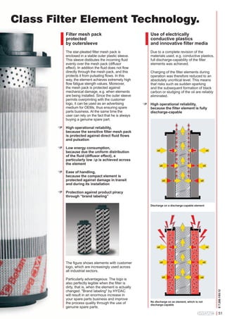
- 1. Class Filter Element Technology. Filter mesh pack protected by outersleeve Use of electrically conductive plastics and innovative filter media The star-pleated filter mesh pack is enclosed in a stable outer plastic sleeve. This sleeve distibutes the incoming fluid evenly over the mesh pack (diffusor effect). In addition the fluid does not flow directly through the mesh pack, and this protects it from pulsating flows. In this way, the element achieves extremely high flow fatigue stength values. Moreover, the mesh pack is protected against mechanical damage, e.g. when elements are being installed. Since the outer sleeve permits overprinting with the customer logo, it can be used as an advertising medium for OEMs, thus ensuring spare parts business. At the same time the user can rely on the fact that he is always buying a genuine spare part. Due to a complete revision of the materials used, e.g. conductive plastics, full discharge-capability of the filter elements was achieved. Charging of the filter elements during operation was therefore reduced to an absolutely uncritical level. This means that risks such as sudden sparking and the subsequent formation of black carbon or sludging of the oil are reliably eliminated. High operational reliability, because the filter element is fully discharge-capable High operational reliability, because the sensitive filter mesh pack is protected against direct fluid flows and pulsation Low energy consumption, because due the uniform distribution of the fluid (diffusor effect), a particularly low ∆p is achieved across the element oil oil oil Ease of handling, because the compact element is protected against damage in transit and during its installation oil oil oil Protection against product piracy through “brand labeling” Discharge on a discharge-capable element oil Particularly advantageous: The logo is also perfectly legible when the filter is dirty, that is, when the element is actually changed. "Brand labeling" by HYDAC will result in an enormous increase in your spare parts business and improve the process quality through the use of genuine spare parts. oil oil oil Öl oil No discharge on an element, which is not discharge-capable E 7.206.1/03.12 The figure shows elements with customer logo, which are increasingly used across all industrial sectors. oil 51
- 3. Flexmicron P (Premium) Description The filter elements of the FlexMicron P (Premium) product line are durable elements in pleat technology, manufactured in meltblown or highquality fibreglass technique. They are used particularly in applications requiring highest levels of cleanliness. Technical Details General data Length Filtration rating ßx-values Filtration efficiency 10", 20", 30", 40" 1 ... 40 µm up to 20,000 up to 99.99 % Applications zzHigh-end industrial part washing systems (aqueous & hydrocarbon up to 100 °C) zzFlushing rigs (after part washing systems) zzTest rigs (fuel injection, braking and steering systems) zzSuperfinishing with cooling lubricants (honing, grinding, turning, milling, deburring) zzOffline filtration in large hydraulic systems zzOffline filtration in lubrication systems zzFilling systems used in cleanliness applications zzMining and metallurgy zzMetal-forming (e.g. hydroforming) E 7.624.1/07.12 Special features zzß-values up to 20,000 zzFiltration efficiency up to 99.99% zzFiltration rating 1 ... 40 µm zzVery low starting Δp zzHigh differential pressure stability zzExcellent filtration efficiency, also under pulsation conditions (pressure and flow rate pulsation) zzWide range of adapters zzMaterials: Polyester, glass fibre zzPleat technology zzExcellent fluid compatibility zzCommonly used element geometry 235
- 4. R (Resistance) factors Model code Aqueous fluids PES* Element type FM-P = Flexmicron P (Premium) Filtration rating 001 = 1 µm 003 = 3 µm 005 = 5 µm 010 = 10 µm 020 = 20 µm 030 = 30 µm 040 = 40 µm Filtration rating Element length 10 = 10" 20 = 20" 30 = 30" 40 = 40" Seal material F = FKM (FPM, Viton®) N = NBR E = EPDM Other types of element on request GF** 10.4 7.5 4.4 1.8 1.8 0.9 0.9 5.4 4.3 3.2 - 1 µm 3 µm 5 µm 10 µm 20 µm 30 µm 40 µm Oils * ß > 5,000 ** ß > 20,000 Maximum differential pressure Δpmax and permitted temperature range at the element: Filter material PES 8 bar 6.5 bar 5 bar Fluid temperature Filter material PES = Polyester GF = Glass fibre End cap type 1 = plug-in adapter (1x 222 O-ring), flat end cap, element Ø 64 mm 2 = plug-in adapter (2x 222 O-ring), flat end cap, element Ø 64 mm 3 = plug-in adapter (2x 222 O-ring), flat end cap, element Ø 70 mm 5 = plug-in adapter (2x 222 O-ring), locating spigot, element Ø 70 mm 7 = bayonet (2x 226 O-ring), locating spigot, element Ø 70 mm 10 = open (gasket DOE), element Ø 64 mm 12 = Cuno adapter (hanging elements), element Ø 64 mm others on request PES* 32.0 24.0 18.0 17.0 15.0 14.0 14.0 N 40 FM-P 005 - PES 1 F -10 ... 30 °C -10 ... 60 °C -10 ... 100 °C Sizing The total pressure drop of the filter at a certain flow rate is the sum of the housing Δp and the element Δp. The housing pressure drop can be determined using the pressure drop curves. The pressure drop of the elements is calculated using the R factors. The following calculation is based on clean filter elements. Δp [bar] = R x V (mm²/s) x Q (l/min) n x l (inch) x 1000 R V Q n l R factor Viscosity (mm²/s) Flow rate (l/min) No. of elements Element length (inch) = = = = = Maximum permitted flow rate Element length 10" 13" 20" 30" 40" Maximum permitted flow rate 20 l/min 26 l/min 40 l/min 60 l/min 80 l/min E 7.624.1/07.12 Other flow rates on request. 236
- 5. Dimensions of Flexmicron P Elements Type 1: Plug-in adapter 1 x O-ring (-222), flat end cap 64 45.5 L2 Type 2: Plug-in adapter 2 x O-ring (-222), flat end cap L1 Type 3: Plug-in adapter 2 x O-ring (-222), flat end cap L2 70 45.5 L1 Type 5: Plug-in adapter 2x O-ring (-222), locating spigot L2 L1 70 45.5 25.5 22.5 14 L1 in mm 263 339 517 771 1025 L2 in mm 18 18 18 18 18 Description N10FM-P... N13FM-P... N20FM-P... N30FM-P... N40FM-P... L1 in mm L2 in mm Description N10FM-P... N13FM-P... N20FM-P... N30FM-P... N40FM-P... L1 in mm L2 in mm 70 N13FM-P... 58.5 L1 Description N10FM-P... N13FM-P... N20FM-P... N30FM-P... N40FM-P... Description N10FM-P... Type 7: Bayonet, 2x O-ring (-226), locating spigot 25.5 64 45.5 L2 L1 in mm 263 339 517 771 N20FM-P... N30FM-P... N40FM-P... Description N10FM-P... Type 10: Gasket (DOE), open L1 N13FM-P... 55 64 3 N20FM-P... N30FM-P... N40FM-P... L2 in mm 18 18 18 18 18 1025 263 339 517 771 1025 263 339 517 771 1025 18 18 18 18 18 L1 in mm 241 317 495 749 1003 L1 in mm 254 330 508 762 N40MR-P...-990 L1 in mm 977 6.5 64 65 61 L1 1016 988 Description N37FM-P... Type 12: Cuno adapter (suspended elements) 18 18 18 18 18 E 7.624.1/07.12 L1 Description N10FM-P... N13FM-P... N20FM-P... N30FM-P... N40FM-P... 237
- 6. E 7.624.1/07.12 NOTE 238 The information in this brochure relates to the operating conditions and applications described. For applications and operating conditions not described, please contact the relevant technical department. Subject to technical modifications. HYDAC Filter Systems GmbH Industriegebiet D-66280 Sulzbach / Saar Tel.:+49 (0) 6897/509-01 Fax:+49 (0) 6897/509-846 Internet: www.hydac.com E-Mail: filtersystems@hydac.com
- 7. Flexmicron S (Standard) Description The filter elements in the Flexmicron S (Standard) product line are SpunSpray depth filter elements produced using melt-blown technology. They are used particularly in applications where a high level of fluid cleanliness and material purity is required. Technical specifications General data Length Filtration rating Filtration efficiency 10", 20", 30", 40" 1 ... 90 µm 99.8 % Applications zzIndustrial part washing systems (aqueous up to 60 °C) zzTransmission test rigs, hydraulic test rigs zzSuperfinishing with cooling lubricants zzPaints and coatings zzCooling circuits on machines zzFilling systems zzRefineries, chemical industry zzSemiconductor industry zzOffline filtration in large hydraulic systems zzOffline filtration in lubrication systems E 7.625.0/11.10 Special features zzFiltration rating 1 ... 90 µm zzMaterial purity zzCaps welded, not glued zzWide range of adapters zzGood price/performance ratio zzMaterials: Polypropylene, Polyamide zzSpunSpray technology, material not wound zzHigh level of cleanliness due to graded depth filter construction zzHigh contamination retention due to large depth effect of the filter material zzExcellent fluid compatibility zzStandard element geometry 239
- 8. R (Resistance) factors Model code Aqueous fluids N 40 FM-S 005 - PP 1 F Element type FM-S = Flexmicron S (Standard) Filtration rating 001 = 1 µm 003 = 3 µm 005 = 5 µm 010 = 10 µm 020 = 20 µm 030 = 30 µm 040 = 40 µm 050 = 50 µm 070 = 70 µm 090 = 90 µm Filter material PP = Polypropylene PA = Polyamide End cap type 0 = compression ring (DOE), no cap or seal (Ø 63 mm) 1 = plug-in adapter (1x 222 O-ring), flat end cap (Ø 64 mm) 2 = plug-in adapter (2x 222 O-ring), flat end cap (Ø 64 mm) 10 = gasket (DOE) (Ø 63 mm) 13 = plug-in adapter (2x 222 O-ring), locating spigot (Ø 64 mm) 14 = bayonet (2x 226 O-ring), locating spigot (Ø 64 mm) others on request Seal material F = FPM (Viton) N = NBR E = EPDM PA 274 116 42 15 11 6 3.8 1.9 1.1 0.6 1 µm 3 µm 5 µm 10 µm 20 µm 30 µm 40 µm 50 µm 70 µm 90 µm Filtration rating Element length 10 = 10" 20 = 20" 30 = 30" 40 = 40" PP 321 186 132 99 54 16 12 10 8 6 Maximum differential pressure Δpmax and permitted temperature range at the element: Fluid temperature -10..30 °C -10...60 °C -10...100 °C Filter material PP PA 7 bar 5.5 bar 3.5 bar 4 bar 2 bar – Sizing The total pressure drop of the filter at a certain flow rate is the sum of the housing Δp and the element Δp. The housing pressure drop can be determined using the pressure drop curves. The pressure drop of the elements is calculated using the R factors. The following calculation is based on clean filter elements. Other element types on request. Δp [bar] = R x V (mm²/s) x Q (l/min) n x l (inch) x 1000 R = R factor V = Viscosity (mm²/s) Q = Flow rate (l/min) n = No. of elements l = Element length (inch) Max. permitted flow rate Element length 10" 20" 30" 40" Max. permitted flow rate 15 l/min 30 l/min 45 l/min 60 l/min E 7.625.0/11.10 Other flow rates on request. 240
- 9. Dimensions of Flexmicron S Elements Designation N10FM-S... N20FM-S... N30FM-S... N40FM-S... L1 in mm 254 508 762 1016 Type 1: Plug-in adapter, 1 x O-ring (-222), flat end cap Designation N10FM-S... N20FM-S... N30FM-S... N40FM-S... L1 in mm 263 517 771 1025 L2 in mm 20 20 20 20 Type 2: Plug-in adapter, 2 x O-ring (-222), flat end cap Designation N10FM-S... N20FM-S... N30FM-S... N40FM-S... L1 in mm 263 517 771 1025 L2 in mm 20 20 20 20 Type 10: Gasket (DOE) Designation N10FM-S... N20FM-S... N30FM-S... N40FM-S... L1 in mm 254 508 762 1016 Type 13: Plug-in adapter, 2 x O-ring (-222), locating spigot Designation N10FM-S... N20FM-S... N30FM-S... N40FM-S... L1 in mm 263 517 771 1025 Type 14: Bayonet, 2 x O-ring (-226), locating spigot Designation N10FM-S... N20FM-S... N30FM-S... N40FM-S... L1 in mm 241 495 749 1003 E 7.625.0/11.10 Type 0: Compression ring (DOE), no cap or seal 241
- 10. E 7.625.0/11.10 Note 242 The information in this brochure relates to the operating conditions and applications described. For applications and operating conditions not described, please contact the relevant technical department. Subject to technical modifications. HYDAC Filter Systems GmbH Industriegebiet D-66280 Sulzbach / Saar Tel.:+49 (0) 6897/509-01 Fax:+49 (0) 6897/509-846 Internet: www.hydac.com E-Mail: filtersystems@hydac.com
- 11. Flexmicron E (Economy) Designation The filter elements in the Flexmicron E (Economy) product line are depth filter elements produced using meltblown technology. They are used particularly in applications where an average level of fluid cleanliness and material purity is required and they provide a costeffective solution. Technical specifications General data Length Filtration rating Filtration efficiency 10", 20", 30", 40" 1 ... 90 µm 95 % Applications zzIndustrial part washing systems (aqueous up to 60 °C) zzPaints and coatings zzCooling circuits on machinery zzRefineries, chemical industry zzProcesses using cooling lubricants Special features E 7.626.0/11.10 zzFiltration efficiency 95 % zzFiltration rating 1 ... 90 µm zzMaterial purity zzEnd caps welded, not glued zzWide range of adapters zzCost-effective zzMaterials: Polypropylene zzSpunSpray technology, material not wound zzExcellent fluid compatibility zzStandard element geometry zzGood level of cleanliness due to graded depth filter construction zzHigh contamination retention due to large depth effect of the filter material zzManufactured without any contact with oil or silicon, so can be used to filter paints and coatings 243
- 12. R (Resistance) Factors Model code Aqueous fluids PP N 40 FM-E 005 - PP 1 F Element type FM-E = Flexmicron E (Economy) Filtration rating 001 = 1 µm 003 = 3 µm 005 = 5 µm 010 = 10 µm 020 = 20 µm 030 = 30 µm 040 = 40 µm 050 = 50 µm 070 = 70 µm Filter material PP = Polypropylene End cap type 0 = compression ring (DOE), no cap or seal (Ø 63 mm) 1 = plug-in adapter (1x 222 O-ring), flat end cap (Ø 64 mm) 2 = plug-in adapter (2x 222 O-ring), flat end cap (Ø 64 mm) 10 = gasket (DOE) (Ø 63 mm) 13 = plug-in adapter (2x 222 O-ring), locating spigot (Ø 64 mm) 14 = bayonet (2x 226 O-ring), locating spigot (Ø 64 mm) others on request Seal material F = FPM (Viton) N = NBR E = EPDM Other types of element on request. 37 29 20 11 8 6.8 5.4 4.2 3.1 1 µm 3 µm 5 µm 10 µm 20 µm 30 µm 40 µm 50 µm 70 µm Filtration rating Element length 10 = 10" 20 = 20" 30 = 30" 40 = 40" Maximum differential pressure Δpmax and permitted temperature range at the element: Filter material Fluid temperature PP 4 bar 2 bar – -10..30 °C -10...60 °C -10...100 °C Sizing The total pressure drop of the filter at a certain flow rate is the sum of the housing Δp and the element Δp. The housing pressure drop can be determined using the pressure drop curves. The pressure drop of the elements is calculated using the R factors. The following calculation is based on clean filter elements. Δp [bar] = R x V (mm²/s) x Q (l/min) n x l (inch) x 1000 R = R factor V = Viscosity (mm²/s) Q = Flow rate (l/min) n = No. of elements l = Element length (inch) Max. permitted flow rate Element length 10" 20" 30" 40" Max. permitted flow rate 15 l/min 30 l/min 45 l/min 60 l/min E 7.626.0/11.10 Other flow rates on request. 244
- 13. Dimensions of Flexmicron E Elements Designation N10FM-E... N20FM-E... N30FM-E... N40FM-E... L1 in mm 254 508 762 1016 Type 1: Plug-in adapter, 1 x O-ring (-222), flat end cap Designation N10FM-E... N20FM-E... N30FM-E... N40FM-E... L1 in mm 263 517 771 1025 L2 in mm 20 20 20 20 Type 2: Plug-in adapter, 2 x O-ring (-222), flat end cap Designation N10FM-E... N20FM-E... N30FM-E... N40FM-E... L1 in mm 263 517 771 1025 L2 in mm 20 20 20 20 Type 10: Gasket (DOE) Designation N10FM-E... N20FM-E... N30FM-E... N40FM-E... L1 in mm 254 508 762 1016 Type 13: Plug-in adapter, 2 x O-ring (-222), locating spigot Designation N10FM-E... N20FM-E... N30FM-E... N40FM-E... L1 in mm 263 517 771 1025 Type 14: Bayonet, 2 x O-ring (-226), locating spigot Designation N10FM-E... N20FM-E... N30FM-E... N40FM-E... L1 in mm 241 495 749 1003 E 7.626.0/11.10 Type 0: Compression ring (DOE), no cap or seal 245
- 14. E 7.626.0/11.10 Note 246 The information in this brochure relates to the operating conditions and applications described. For applications and operating conditions not described, please contact the relevant technical department. Subject to technical modifications. HYDAC Filter Systems GmbH Industriegebiet D-66280 Sulzbach / Saar Tel.:+49 (0) 6897/509-01 Fax:+49 (0) 6897/509-846 Internet: www.hydac.com E-Mail: filtersystems@hydac.com
- 15. Trimicron Filter Element N1TM, N3TM Description The filter elements in the Trimicron series have been specially developed for the combined filtration of: zzFinest solid particle contamination zzWater zzOil ageing product from hydraulic and lubrication oils in the bypass flow. They are a combination of pleated and SpunSpray depth filter elements. The filter layers used are produced using melt-blown technology (synthetic fibres). Technical specifications General specifications Contamination retention capacity ISOMTD at ∆P = 2.5 bar Water retention capacity Beta value ß 5 (c) @ 2 bar Filtration rating Differential pressure at starting point Permitted fluid temperature range Storage temperature range N1 ≈ 410 g N3 ≈ 2500 g ≈ 680 ml > 1,000 ≈ 2.2 l > 1,000 3 µm < 0.1 bar -10 ... 80 °C 5 … 40 °C Applications zzOffline filtration in lubrication systems (e.g. in wind turbines) zzOffline filtration in hydraulic systems zzTransmission and hydraulic test rigs Special features E 7.635.0/12.12 zzExcellent filtration performance (ß 5 (c) > 1000) zzLow initial differential pressure zzHigh contamination retention capacity zzFine particle contamination, water and oil ageing products removed by depth filter material zzBroad range of fluid compatibility zzSimple element change 247
- 16. Note Order details N – 1 – TM – 003 /- F Nominal flow rate 1 = nominal flow rate 1 l/min 3 = nominal flow rate 3 l/min The information in this brochure relates to the operating conditions and applications described. For applications and operating conditions not described, please contact the relevant technical department. Subject to technical modifications. Element type TM = Trimicron Filtration rating 003 = 3 µm Seal material N = NBR F = FKM (FPM, Viton®) Element differential pressure N1TM 3.0 2.5 Q ΔP in bar 2.0 min l/ =5 1.5 in Q = 2 l/m Q = 1 l/min 1.0 0.5 0 0 200 400 600 800 1000 Viscosity in mm2/s Element differential pressure N3TM 0.7 in /m 0.6 Q l =6 ΔP in bar 0.5 0.4 0.3 viscosity / (mm2/s) Q=3 0.2 l/min in Q = 1 l/m 0.1 E 7.635.0/12.12 0 248 0 200 400 600 Viscosity in mm2/s 800 1000 HYDAC Filter Systems GmbH Industriegebiet D-66280 Sulzbach/Saar Tel.:+49 (0) 6897/509-01 Fax:+49 (0) 6897/509-846 Internet: www.hydac.com E-Mail: filtersystems@hydac.com
- 17. Wombat Filter Element WB Description The Wombat element is a pleated filter element designed to flow from the inside outward and filter high amounts of contamination with high efficiency. The Wombat element can be installed in bag filter housings and replace the existing filter bag. An adapter kit is needed for filtration. This only needs to be installed once and consists of a retainer basket and seal. Bar magnets are available as an accessory for filtering magnetic particles. Technical specifications General specifications Size Max. differential pressure Filtration rating Degree of separation Filter material Cap material Max. temperature N100WB 2.5 bar 1 - 90 µm > 99.8 % Polyester (PES) Polypropylene (PP) 70 °C N200WB 2.5 bar 1 - 90 µm > 99.8 % Polyester (PES) Polypropylene (PP) 70 °C Applications Filtering cleaning and processing liquids Pre-filtering fluids in hydraulic and lubrication systems As a working and police filter in cleaning systems (washing bays) As a protective filter in machine tools Advantages vs. filter bags E 7.634.0/11.12 Very high fluid purity Longer service life Greater contamination retention capacity Lower loss of pressure (up to 30%) More stable element design High temperature stability Conical design for faster element change 249
- 18. R (Resistance) factors Model code N 200 WB 005 - PES F for water-based media R factors Element size 100 = for filter bag size 1 200 = for filter bag size 2 Filtration rating Element type WB = Wombat Filtration rating 001 = 1 µm 003 = 3 µm 005 = 5 µm 010 = 10 µm 020 = 20 µm 030 = 30 µm 040 = 40 µm A, B, C, D, E = special models (see table below for degree of separation) Degree of separation for special models A - E: Smallest particle size (µm) with a degree of separation greater than C D E 7.634.0/11.12 E 250 0.12 0.10 0.08 0.07 0.07 0.06 0.05 0.04 0.04 0.03 0.02 The total pressure drop of the filter at a certain flow rate is the sum of the housing Δp and the element Δp. The housing pressure drop can be determined using the pressure drop curves. The pressure drop of the elements is calculated using the R factors. The following calculation is based on clean filter elements. Sealing material F = FPM N = NBR B N 200 0.20 0.18 0.14 0.13 0.13 0.11 0.09 0.08 0.07 0.06 0.05 Sizing Filter material PES = Polyester Model A N 100 1 µm 3 µm 5 µm 10 µm 20 µm 30 µm A B C D E > 99.8% 99% 95% 80% 60 70 85 105 135 40 50 65 85 110 30 40 50 70 95 25 30 40 60 85 Δp [mbar] = R x V (mm²/s) x Q (l/min) n R = R factor V = viscosity (mm²/s) Q = flow rate (l/min) n = no. of elements
- 19. Accessories Adapter kits for installing the Wombat element in bag filter housing Adapter Kit TL-100-F Ø1 Ø 160 Ø 155 78 302 Adapter Kit TL-200-F 710 L1 L1 Adapter Kit EL-100-F 18 9 Ø 155 317 Adapter Kit EL-200-F Ø Adapter Kit EL-100-F, Mat. No. 3683976 for e.g. Eaton Ecoline Housing BG 1 Adapter Kit EL-200-F, Mat. No. 3681844 for e.g. Eaton Ecoline Housing BG 2 Adapter Kit FL-100-F, Mat. No. 3691554 for e.g. Eaton Flowline Housing BG 1 Adapter Kit FL-200-F, Mat. No. 3691595 for e.g. Eaton Flowline Housing BG 2 L1 L1 Ø 178 Ø 160 Adapter Kit TL-100-F, Mat. No. 3674956 for e.g. Eaton Topline Housing BG 1 Adapter Kit TL-200-F, Mat. No. 3549057 for e.g. Eaton Topline Housing BG 2 720 Adapter Kit FL-100-F 317 Adapter Kit FL-200-F 720 12 45 Others on request Bar magnet insert for filtering magnetic particles from fluid L1 Bar magnet insert N100 L1 Ø 30 Bar Magnet Insert N100 Mat. No. 3633896 for Wombat element N100 Bar Magnet Insert N200 Mat. No. 3601237 for Wombat element N200 196 Bar Magnet Insert N200 540 E 7.634.0/11.12 Separation Element for Bar Magnet Mat. No. 3639116 251