ADCMT 7352 Series Digital Multimeter
•
0 recomendaciones•86 vistas

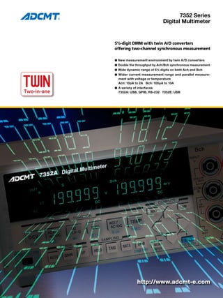
5½-digit DMM with twin A/D converters offering two-channel synchronous measurement ● New measurement environment by twin A/D converters ● Double the throughput by Ach/Bch synchronous measurement ● Wide dynamic range of 5½ digits on both Ach and Bch ● Wider current measurement range and parallel measurement with voltage or temperature Ach: 10pA to 2A Bch: 100µA to 10A ● A variety of interfaces 7352A: USB, GPIB, RS-232 7352E: USB

Recomendados
Recomendados
Más contenido relacionado
La actualidad más candente
La actualidad más candente (19)
Similar a ADCMT 7352 Series Digital Multimeter
Similar a ADCMT 7352 Series Digital Multimeter (20)
Más de NIHON DENKEI SINGAPORE
Más de NIHON DENKEI SINGAPORE (20)
Último
Último (20)
ADCMT 7352 Series Digital Multimeter
- 1. 7352 Series Digital Multimeter 5½-digit DMM with twin A/D converters offering two-channel synchronous measurement ● New measurement environment by twin A/D converters ● Double the throughput by Ach/Bch synchronous measurement ● Wide dynamic range of 5½ digits on both Ach and Bch ● Wider current measurement range and parallel measure- ment with voltage or temperature Ach: 10pA to 2A Bch: 100µA to 10A ● A variety of interfaces 7352A: USB, GPIB, RS-232 7352E: USB TWIN Two-in-one TWO-IN-ONE http://www.adcmt-e.com
- 2. 2 A/D converter Photo coupler A/D converter LOGIC CPU Ach Bch Hi Lo Hi Lo A new concept digital multimeter 7352 series has ap- peared, offering various applications and improved throughput. The 7352A/7352E is the next-generation digital multi- meter having twin-A/D converters that enable fully-inde- pendent measurement of two-channel signals, and is suit- able for high-speed measurement, parallel measurement of different functions and multi-channel measurement by configuring a system. The channel A (Ach) has basic measurement functions for DC voltage/current, AC voltage/current, resistance and frequency, while the channel B (Bch) has DC volt- age/current, AC current and temperature measurement functions. Thus, higher throughput can be obtained with Ach/Bch synchronous measurement or Ach/Bch parallel measurement of different functions. Furthermore, the dynamic range of current measurement has been broadened significantly, enabling measurement from low current of 10pA to high current of 10A. The 7352A is equipped with an RS-232 interface in ad- dition to USB and GPIB interfaces for use in R&D and production lines. The 7352E is equipped with a USB in- terface for low-cost system configuration. The remote command language not only complies with the conventional ADC commands and SCPI, but also is compatible with that of the digital multimeter R6452A. Conventional dual DMM 7352A/E Ach Bch Hi Lo Hi Lo 5MΩ 5MΩ A/D converter LOGIC CPU Photo coupler Photo coupler Two-in-one TWO Evolution from Dual to TWIN ● Measures Ach and Bch alternately with a single A/D converter. ● The impedance between Ach and Bch is only 5MW because Bch is a differential input circuit. The potential difference between the channels due to a differential resistance error causes a large error in Bch measurement. (0.05%) ● Synchronous measurement by twin A/D converters ● Completely isolated between the channels Open up a new age of digital multimeters by real two-channel synchronous measurement
- 3. 3 Twin A/D converters realize synchronous measurement of Ach and Bch functions. Even at the sampling rate per PLC at which noise rejection is possible, two-function measurement data can be obtained without switching the functions, allowing the significant im- provement of the system throughput. In building up a system, system interfaces are available for easy connection with a programmable controller. The 7352A is equipped with USB, GPIB and RS-232 interfaces as standard. Since Bch is fully independent from Ach, its measurement is not affected by the potential difference between them. In addition, high-accuracy Bch measurement is available with 5½-digit display. Moreover, this series is capable of high-accuracy parallel measurement of different measurement functions such as voltage/current, voltage or current/temperature, or AC/DC be- tween Ach and Bch. The broadened dynamic range enables measurement of low power consumption. Ach has measurement ranges from 2µA (10pA resolution) to 2A, and Bch has 10A measurement range (100µA resolution). Two functions such as current/voltage or current/temperature can be measured with high sensitivity and resolution and these results are dual-displayed. Improve the system throughput with minimum dispersion? Synchronization Various Solutions to Meet Your Needs! Measure Bch as well as Ach highly accurately? High accuracy Measure much lower current? Low current Build up a system easily? System configuration
- 4. Thermocouple Regulator circuit Load A A V f V T Rear input Load Regulator circuit Thermocouple Thermocouple Load A A V V T DC/DC converter Io Vo T1 T2 Load Regulation Rear input Load Thermocouple DC/DC converter 4 Testing of Power Unit The conventional dual DMM has the following problems in testing a power unit. •Switching measurement is required because of a single A/D converter. •It takes time to switch the AC-DC functions. •When there is a potential difference between Ach LO and Bch LO, a large measurement error occurs on Bch. Thus, in such measurement, two digital multimeters are required. On the other hand, the 7352A/7352E is provided with com- pletely isolated Ach, Bch and TEMP, and is equipped with two independent A/D converters. Thus, switching measurement and functional change are unnecessary, and high-throughput measurement is available without influence between the channels. It has six measurement capabilities: AC input volt- age/current and frequency on Ach, DC output voltage/current on Bch, and temperature on rear TEMP. Applications The input and output characteristics, load regulation character- istics, conversion efficiency, and rise in temperature of a DC/DC converter can be evaluated by a single unit of the 7352A/7352E. This series has five measurement capabilities: input voltage/cur- rent on Ach, output voltage/current on Bch and temperature on rear TEMP. In addition, change in input current or temperature against load current fluctuation can be measured in real time by using two-channel parallel measurement. Thanks to complete isolation between the channels, the input and output of an isolated DC/DC converter can be measured by just one unit. The channel outputs of a multi-output converter can be also monitored simultaneously by using one unit per two channels. Even in such case, there is no crosstalk between the channels. Evaluation of DC/DC Converter
- 5. 7352A 7352E 5 DCV ACV ACV (AC+DC) Ω LP−Ω DCI ACI ACI (AC+DC) Continuity Diode FREQ DCV DCI ACI ACI (AC+DC) TEMP Ach Bch 1μV−1000V True RMS 1μV−700V 1mΩ−200MΩ 10pA−2A Trure RMS 1nA−2A − − 10Hz−300kHz 1μV−200V 100μA−10A True RMS 100μA−10A K, T thermocouple OFF Single measure- ment Single measure- ment DCV ACV ACV (AC+DC) Ω LP−Ω DCI ACI ACI (AC+DC) Continuity Diode FREQ DCV DCI ACI ACI (AC+DC) TEMP Measurement function Measurement Range Sequential measurement (Two functions are alternately measured by switching them.) Synchronous measurement Synchronous measurement (Two functions are simultaneously measured.) Sequential measurement Ach Bch Right side display The maximum sampling rate is 140 readings/sec for 1-channel single measurement and 123 readings/sec for 2-channel synchronous measurement. The sampling rate per PLC at which noise rejection is possible is 46 readings/sec for single measurement and 40 readings/sec for synchronous mea- surement that are the highest rate in this class. RATE mode Integration time Display digit DCV DCI 2WΩ LP−2WΩ ACV ACI continuity diode ACV (AC+DC) ACI (AC+DC) DCV DCI 2WΩ LP−2WΩ ACV ACI continuity diode Single measurement Synchronous measurement FAST MED (50Hz) MED (60Hz) SLOW1 SLOW2 2ms 1PLC 1PLC 100ms 200ms 19999 199999 199999 199999 199999 140 rdgs/s (7.1ms) 40 rdgs/s (25ms) 46 rdgs/s (21.7ms) 9.5 rdgs/s (105ms) 4.9 rdgs/s (205ms) 30 rdgs/s (33ms) 19 rdgs/s (52ms) 22 rdgs/s (45.4ms) 4.7 rdgs/s (212ms) 2.4 rdgs/s (412ms) 123 rdgs/s (8.1ms) 38 rdgs/s (26.3ms) 43.5 rdgs/s (23ms) 9.5 rdgs/s (105ms) 4.9 rdgs/s (205ms) Conditions: Auto-range: OFF, Auto-zero: OFF, Calculation: OFF, Display: OFF Left side display Right and Left Display Combinations and Measurement Functions Measurement Time USB interface External trigger GPIB interface RS-232 interface Ach input terminal Bch input terminal TEMP input terminal
- 6. 6 Specifications Unless otherwise specified, the measurement accuracy is guaranteed for one year under the following conditions: Temperature; 23 ±5°C, rela- tive humidity; 85% or less (75% or less in resistance measurement of 20MΩ or more and low power resistance measurement of 2MΩ or more). Temperature coefficient: For the 4½-digit display, the digit error is reduced to 1/10. Range Maximum display Resolution Input impedance 200mV 2000mV 20V 200V 1000V 199.99 1999.9 19.999 199.99 1099.9 199.999 1999.99 19.9999 199.999 1099.99 10μV 100μV 1mV 10mV 100mV 1μV 10μV 100μV 1mV 10mV More than 1GΩ More than 1GΩ 10MΩ±1% 10MΩ±1% 10MΩ±1% 0.012+4 0.011+2 0.015+2 0.015+2 0.015+2 0.012+6 0.011+2 0.015+4 0.015+4 0.015+4 0.012+6 0.011+2 0.015+4 0.015+4 0.015+4 15+0.85 15+0.2 20+0.25 20+0.25 20+0.25 15+2 15+1.5 20+1.5 20+1.5 20+1.5 Measurement accuracy *1 ± (% of reading + digits) Temperature coefficient ± (ppm of reading + digits)/°C FAST MED/SLOW1,2 FAST MED/SLOW1,2 FAST MED SLOW1,2 Auto-zero ON Auto-zero OFF ■ DC Voltage Measurement (DCV-Ach) ■ Noise rejection ratio *1 For Auto-zero ON. For Auto-zero OFF, 1 digit is added to the digit error. Effective common mode noise rejection ratio (Unbalanced impedance of 1kΩ) Normal mode noise rejection ratio DC 50/60Hz±0.08% 50/60Hz±0.08% Approx. 130dB Approx. 60dB 0dB Approx. 130dB Approx. 120dB Approx. 60dB MED/SLOW1,2 FAST ■ Maximum input Between VΩHz and COM A terminals 1000Vpeak ■ AC Voltage Measurement (ACV, ACV (AC+DC)-Ach) Measurement method: True RMS measurement, RMS display Input range: 5% or more of a full scale Crest Factor: 3 : 1 at a full scale (This is restricted to the maximum input.) Temperature coefficient: (1/10 of measurement accuracy that includes the addi- tional error)/°C in each range and frequency range Response time: Approx. 1s (Time until the measurement value reaches within 0.1% of the final value in the same range) Range Maximum display Resolution Input impedance 200mV 2000mV 20V 200V 700V 199.99 1999.9 19.999 199.99 749.9 199.999 1999.99 19.9999 199.999 749.99 10μV 100μV 1mV 10mV 100mV 1μV 10μV 100μV 1mV 10mV 1MΩ±2%, 140pF or less 0.38+140 0.38+140 0.38+140 0.38+140 0.38+100 0.11+120 0.11+120 0.11+120 0.11+120 0.11+100 0.1+100 0.1+100 0.1+100 0.1+100 0.1+100 0.25+150 0.2+150 0.2+150 0.2+150 − 0.7+240 0.6+240 0.6+240 0.6+240 − Measurement accuracy *2 ±(% of reading + digits) FAST/MED SLOW1,2 FAST/MED SLOW1,2 20-45Hz 45-100Hz 100-20kHz 20k-50kHz 50k-100kHz ACV *2 For a sine-wave input. When RATE is set to FAST or MED, the digit error is reduced to 1/10 of its specification. Range Maximum display Resolution Input impedance 200mV 2000mV 20V 200V 700V 199.9 1999 19.99 199.9 749 199.99 1999.9 19.999 199.99 749.9 100μV 1000μV 10mV 100mV 1000mV 10μV 100μV 1000μV 10mV 100mV 1MΩ±2%, 140pF or less 0.38+14 0.38+14 0.38+14 0.38+14 0.38+10 0.11+14 0.11+14 0.11+14 0.11+14 0.11+10 0.1+14 0.1+14 0.1+14 0.1+14 0.1+10 0.25+15 0.2+15 0.2+15 0.2+15 − 0.7+24 0.6+24 0.6+24 0.6+24 − Measurement accuracy *2 ±(% of reading + digits) FAST/MED SLOW1,2 FAST/MED SLOW1,2 20-45Hz 45-100Hz 100-20kHz 20k-50kHz 50k-100kHz ACV (AC+DC) *2 For a sine-wave input. When RATE is set to FAST or MED, the digit error is reduced to 1/10 of its specification. Additional crest factor error (For a non sine-wave input voltage) ±(% of reading + % of range) 1-2 2-3 0+0.05 0+0.15 Maximum input Between VΩHz and COM A terminals 700Vrms, 1000Vpeak, 2.2×10⁷ V Hz ■ Resistance Measurement (2WΩ, LP-2WΩ-Ach) 2WΩ measurement Range Maximum display Resolution Measurement current 199.99 1999.9 19.999 199.99 1999.9 19.999 199.99 199.999 1999.99 19.9999 199.999 1999.99 19.9999 199.999 10mΩ 100mΩ 1Ω 10Ω 100Ω 1kΩ 10kΩ 1mΩ 10mΩ 100mΩ 1Ω 10Ω 100Ω 1kΩ 1mA 1mA 100μA 10μA 1μA 100nA 10nA 0.02+4 0.02+2 0.02+2 0.02+2 0.03+2 0.2+2 1.5+2 0.02+9 0.02+5 0.02+5 0.02+5 0.03+10 0.2+10 1.5+10 0.02+8 0.014+3 0.014+3 0.02+5 0.03+10 0.2+10 1.5+10 20+1 15+0.25 15+0.25 20+0.25 35+2 155+2 1500+2 20+2 15+1.5 15+1.5 20+1.5 35+5 155+5 1500+5 Measurement accuracy *3 ±(% of reading + digits) Temperature coefficient ±(ppm of reading+digits)/°C FAST MED/SLOW1,2 FAST MED/SLOW1,2 FAST MED SLOW1,2 Auto-zero ON Auto-zero OFF Low power measurement (LP-2WΩ) Range Maximum display Resolution Measurement current 200Ω 2000Ω 20kΩ 200kΩ 2000kΩ 20MΩ 199.99 1999.9 19.999 199.99 1999.9 19.999 199.999 1999.99 19.9999 199.999 1999.99 19.9999 10mΩ 100mΩ 1Ω 10Ω 100Ω 1kΩ 1mΩ 10mΩ 100mΩ 1Ω 10Ω 100Ω 1mA 100μA 10μA 1μA 100nA 10nA 0.02+4 0.03+4 0.03+4 0.03+4 0.2+2 1.5+5 0.02+9 0.03+9 0.03+9 0.03+9 0.2+12 1.5+50 0.02+8 0.03+8 0.03+8 0.03+8 0.2+12 1.5+50 20+1 20+1 20+1 30+1 150+2 1500+2 20+5 20+3 20+3 30+3 150+5 1500+5 Measurement accuracy *3 ±(% of reading + digits) Temperature coefficient ±(ppm of reading+digits)/°C FAST MED/SLOW1,2 FAST MED/SLOW1,2 FAST MED SLOW1,2 Auto-zero ON Auto-zero OFF *3 For Auto-zero ON. For Auto-zero OFF, 2 digits are added to the digit error. In addition, the offset error, which consists of the input cable resistance and 0.2W, is added. 200Ω 2000Ω 20kΩ 200kΩ 2000kΩ 20MΩ 200MΩ Additional error to the ACV (AC+DC) measurement ±(% of reading) 20-45Hz 45-100Hz FAST 1.24% 0.06% MED 0.72% − Channel A (Ach)
- 7. 7 ■ DC Current Measurement (DCI-Ach) Range Maximum display Resolution Resistance be- tween terminals (A fuse resistance is included.) 2000nA 20μA 200μA 2000μA 20mA 200mA 2000mA 1999.9 19.999 199.99 1999.9 19.999 199.99 1999.9 1999.99 19.9999 199.999 1999.99 19.9999 199.999 1999.99 100pA 1nA 10nA 100nA 1μA 10μA 100μA 10pA 100pA 1nA 10nA 100nA 1μA 10μA 11.5kΩ or less 0.15+35 0.1+7 0.04+20 0.04+2 0.04+20 0.05+2 0.15+2 0.15+40 0.1+7 0.04+40 0.04+7 0.04+40 0.05+7 0.15+7 0.15+40 0.1+5 0.04+40 0.04+5 0.04+40 0.05+6 0.15+6 150+4 100+1 40+4 40+1 40+4 50+0.6 150+0.6 150+4 100+1.6 40+5 40+1.6 40+5 50+3 150+3 Measurement accuracy *4 ±(% of reading + digits) Temperature coefficient ±(ppm of reading+digits)/°C FAST MED/SLOW1,2 FAST MED/SLOW1,2 FAST MED SLOW1,2 Auto-zero ON Auto-zero OFF 102Ω or less 2Ω or less 0.6Ω or less *4 For Auto-zero ON. For Auto-zero OFF, 2 digits are added to the digit error. Maximum input 2A Input protection 2A/250V fast-blow fuse which is compliant with IEC60127 sheet1 Fuse replacement On the rear panel ■ AC Current Measurement (ACI, ACI (AC+DC)-Ach) Measurement method: True RMS measurement, RMS display Input range: 5% or more of a full scale Crest Factor: 3 : 1 at a full scale Temperature coefficient: (1/10 of measurement accuracy that includes the addi- tional error)/°C in each range and frequency range Response time: Approx. 1s (Time until the measurement value reaches within 0.1% of the final value in the same range) ACI Range Maximum display Resolution Resistance between terminals (A fuse resistance is included.) 200μA 2000μA 20mA 200mA 2000mA 199.99 1999.9 19.999 199.99 1999.9 199.999 1999.99 19.9999 199.999 1999.99 10nA 100nA 1μA 10μA 100μA 1nA 10nA 100nA 1μA 10μA 102Ω or less 0.4+200 0.5+200 0.4+200 0.4+200 0.5+200 0.3+200 0.35+100 0.3+200 0.3+200 0.35+100 0.3+100 0.35+200 0.3+100 0.3+100 0.7+200 Measurement accuracy *2 ±(% of reading + digits) FAST/MED SLOW1,2 FAST/MED SLOW1,2 20-45Hz 45-1kHz 1k-5kHz 2Ω or less 0.6Ω or less ACI (AC+DC) Range Maximum display Resolution Resistance between terminals (A fuse resistance is included.) 200μA 2000μA 20mA 200mA 2000mA 199.9 1999 19.99 199.9 1999 199.99 1999.9 19.999 199.99 1999.9 100nA 1μA 10μA 100μA 1mA 10nA 100nA 1μA 10μA 100μA 102Ω or less 0.4+20 0.5+20 0.4+20 0.4+20 0.5+20 0.3+20 0.35+10 0.3+20 0.3+20 0.35+10 0.3+10 0.35+20 0.3+10 0.3+10 0.7+20 Measurement accuracy *2 ±(% of reading + digits) FAST/MED SLOW1,2 FAST/MED SLOW1,2 20-45Hz 45-1kHz 1k-5kHz 2Ω or less 0.6Ω or less Additional crest factor error (For a non sine-wave) ±(% of reading + % of range) Range 200μA-20mA 200mA, 2000mA Crest factor 1-2 2-3 0+0.05 0+0.05 0+0.15 0.1+0.15 Maximum input 2A Input protection 2A/250V fast-blow fuse which is compliant with IEC60127 sheet 1 Fuse replacement On the rear panel Response time 200MΩ = 2s (Time until the measurement value reaches within 0.1% of the final value) 20MΩ = 0.5s (Time until the measurement value reaches within 0.1% of the final value) Open-circuit voltage 7.5V or less Between VΩHz and COM A terminals 1000Vpeak Maximum input *2 For sine-wave input. When RATE is set to FAST or MED, the digit error is reduced to 1/10 of its specification. *2 For sine-wave input. When RATE is set to FAST or MED, the digit error is reduced to 1/10 of its specification. Additional error to the ACI (AC+DC) measurement ±(% of reading) 20-45Hz 45-1kHz FAST 1.24% 0.06% MED 0.72% − ■ Frequency Measurement (FREQ-Ach) Measurement method: Reciprocal Measurement frequency range 10Hz to 300kHz Measurement accuracy 0.02% of reading A frequency over the above range is displayed but not guaranteed. Input signal condition: For sine-wave Input signal voltage range: 100mVrms to 700Vrms and 10% of each voltage range or more (However, the input signal is restrict- ed to the maximum input.) Sampling rate SLOW MED FAST Gate time 1000ms 100ms 10ms 1Hz to 300kHz 10Hz to 300kHz 100Hz to 300kHz 2.2s 220ms 22ms Gate time Measurement frequency range Maximum measurement period 999999 99999 9999 Maximum display Between VΩHz and COM A terminals 700Vrms, 1000Vpeak, 2.2×10⁷ V Hz Maximum input ■ Diode Measurement-Ach Range Maximum display Resolution Measurement current 2000mV 1999.9 1999.99 100μV 10μV 1mA 0.014+2 0.014+5 0.014+3 15+0.25 15+1.5 Measurement accuracy *5 ±(% of reading + digits) Temperature coefficient ±(ppm of reading+digits)/°C FAST MED/SLOW1,2 FAST MED/SLOW1,2 FAST MED SLOW1,2 Auto-zero ON Auto-zero OFF *5 For Auto-zero ON. For Auto-zero OFF, 2 digits are added to the digit error. In addition, an offset error, which is obtained by multiplying (the resistance of the input cable + 0.3W) by 1mA, is added. Other specifications are the same as the resistance measurement function.
- 8. 8 Channel B (Bch) ■ DC Voltage Measurement (DCV-Bch) Range Maximum display Resolution Input impedance 200mV 2000mV 20V 200V 199.99 1999.9 19.999 199.99 199.999 1999.99 19.9999 199.999 10μV 100μV 1mV 10mV 1μV 10μV 100μV 1mV More than 1GΩ More than 1GΩ 10MΩ±1% 10MΩ±1% 0.012+4 0.011+2 0.015+2 0.015+2 0.012+7 0.011+5 0.015+5 0.015+5 0.012+6 0.011+2 0.015+5 0.015+5 15+0.85 15+0.2 20+0.25 20+0.25 15+2 15+1.5 20+1.5 20+1.5 Measurement accuracy *1 ±(% of reading + digits) Temperature coefficient ±(ppm of reading+digits)/°C FAST MED/SLOW1,2 FAST MED/SLOW1,2 FAST MED SLOW1,2 Auto-zero ON Auto-zero OFF *1 For Auto-zero ON. For Auto-zero OFF, 1 digit is added to the digit error. Noise rejection ratio Effective common mode noise rejection ratio (Unbalanced impedance of 1kΩ) Normal mode noise rejection ratio DC 50/60Hz±0.08% 50/60Hz±0.08% Approx. 130dB Approx. 60dB 0dB Approx. 130dB Approx. 120dB Approx. 60dB MED/SLOW1,2 FAST Maximum input Between V and COM B terminals 200Vpeak ■ DC Current Measurement (DCI-Bch) Range Maximum display Resolution Resistance between terminals (A fuse resistance is included.) 10A 11.999 11.9999 1mA 100μA 0.03Ω or less 0.2+2 0.2+7 0.2+5 200+0.6 200+3 Measurement accuracy *4 ±(% of reading + digits) Temperature coefficient ±(ppm of reading+digits)/°C FAST MED/SLOW1,2 FAST MED/SLOW1,2 FAST MED SLOW1,2 Auto-zero ON Auto-zero OFF *4 For Auto-zero ON. For Auto-zero OFF, 2 digits are added to the digit error. Maximum input 10A Input protection 15A/250V fast-blow fuse with 10000A breaking capacity Fuse replacement Contact ADC Corporation to repair ■ Continuity Measurement-Ach Range Maximum display Resolution Measurement current 2000Ω 1999.9 1999.99 100mΩ 10mΩ 1mA 0.014+2 0.014+5 0.014+3 15+0.25 15+1.5 Measurement accuracy *4 ±(% of reading + digits) Temperature coefficient ±(ppm of reading+digits)/°C FAST MED/SLOW1,2 FAST MED/SLOW1,2 FAST MED SLOW1,2 Auto-zero ON Auto-zero OFF Continuity judgment value: 1Ω to 1000Ω Other specifications are the same as the resistance measurement function. *4 For Auto-zero ON. For Auto-zero OFF, 2 digits are added to the digit error. ■ AC Current Measurement (ACI, ACI (AC+DC)-Bch) Measurement method: True RMS measurement, RMS display Input range: 5% or more of a full scale Crest Factor: 3 : 1 at a full scale Temperature coefficient: (1/10 of measurement accuracy that includes the additional error)/°C in each range and frequency range Response time: Approx. 1s (Time until the measurement value reaches within 0.1% of the final value in the same range) ACI Range Maximum display Resolution Resistance between terminals (A fuse resistance is included.) 10A 11.999 11.9999 1mA 100μA 0.03Ω or less 0.5+200 0.5+200 0.7+200 Measurement accuracy *2 ±(% of reading + digits) FAST/MED SLOW1,2 FAST/MED SLOW1,2 20-45Hz 45-1kHz 1k-5kHz *2 For sine-wave input. When RATE is set to FAST or MED, the digit error is reduced to 1/10 of its specification. ACI (AC+DC) Range Maximum display Resolution Resistance between terminals (A fuse resistance is included.) 10A 11.99 11.999 10mA 1mA 0.03Ω or less 0.5+20 0.5+20 0.7+20 Measurement accuracy *2 ±(% of reading + digits) FAST/MED SLOW1,2 FAST/MED SLOW1,2 20-45Hz 45-1kHz 1k-5kHz *2 For sine-wave input. When RATE is set to FAST or MED, the digit error is reduced to 1/10 of its specification. ■ Temperature Measurement (TEMP-Bch) Input terminal TEMP HI - LO Thermocouple Range -50°C to 1370°C Maximum display Resolution Measurement accuracy 1370.0 0.1°C ±0.15%±3°C -50°C to 400°C 400.0 0.1°C ±0.15%±3°C K (CA) T (CC) Maximum input Between TEMP (HI) and TEMP (LO) terminals 36Vpeak Compliant thermocouple standard: JIS C1602 Cold junction compensation: Internal Additional error to the ACI (AC+DC) measurement ±(% of reading) 20-45Hz 45-1kHz FAST 1.24% 0.06% MED 0.72% − Additional crest factor error (For a non sine-wave) ±(% of reading + % of range) Range 10A Crest factor 1-2 2-3 0+0.05 0.07+0.15 Maximum input 10A Input protection 15A/250V fast-blow fuse with 10000A breaking capacity Fuse replacement Contact ADC Corporation to repair
- 9. 9 General Specifications Operating environment: Ambient temperature: 0°C to 50°C However, 0 to +45°C in cases where 1A or more and 5A or more are simultaneously applied to Ach and Bch respec- tively for the current measurement. Relative humidity: 85% or less, no condensation Storage environment: Ambient temperature: -25°C to 70°C Warm-up time: 60 minutes or more Display: Dual 6-digit and 7-segment vacuum fluorescent display Range switching: Automatic and manual Input method: Floating Measurement method: Integration Overload display: OL Power supply: AC power supply: 100V/120V/220V/240V (Cab be switched by user) Specify the option when ordering. Use a power cable and a fuse that are compliant with the safety standard when changing the power supply voltage. Power supply frequency: 50Hz/60Hz Power consumption: 22VA or below Dimensions: Approx. 212 (W) x 88 (H) x 340 (D) mm Mass: 3.7kg or less Safety: IEC61010-1, EN61010-1 Measurement category II EMC: EN61326 class A External trigger signal (7352A) Connector: BNC Signal level: TTL, detecting the failing edge Pulse width: 1µs or more Supplied Accessories Name Power cable Input cable (red, black) Power fuse (for 100V/120V) Power fuse (for 220V/240V) Overcurrent protection fuse Operation manual Model A01402 CC010001 DFT-AAR315A-1 DFT-AAR25A-1 DFS-AN2A-1 E7352A/E Quantity 1 1 each 1 *6 1 1 *6: Either one is included according to the specified option. Optional Accessories Name Input cable Alligator clip adapter RS-232 cable Terminal adapter JIS rack-mount set EIA rack-mount set Panel-mount set Sheath type thermocouple Model CC010001 A01001 CC015001 A01265 1111 A02263 A02264 A02463 A02464 A02039 A02040 1101-100 1101-130 Remarks Standard accessory Shielded cable 33VAC and 70VDC or less 33VAC and 70VDC or less Twins Twins Twins T (CC) type K (CA) type Calculation Functions Interface Specifications NULL calculation: Display value (NULL) = Measurement value - NULL constant Smoothing calculation: Display value (SM) = Moving average over a specified number of measurements Comparator calculation: Display (HIGH) ← HIGH setting value < Measurement value Display (LOW) ← Measurement value < LOW setting value Display (GO) ← LOW setting value ≤ Measurement value ≤ HIGH setting value Scaling calculation: Display (SCL) = (Measurement value -B) / A × C A, B and C are constants. (Setting value) MAX and MIN calculation: Display value (MAX) = Maximum measurement value after the calculation starts Display value (MIN) = Minimum measurement value after the calculation starts Display value (AVE) = Arithmetic mean after the calculation starts (Remote output only) dB and dBm calculation: db display = 20 log (Measurement value / D) dBm display = 10 log [((Measurement value)2 / D) / 10-3 ] D is constant. (Setting value) Statistical calculation: Number of samples Display value (SAMPLE) = Number of measurement values in the specified range of the measurement memory Maximum value Display value (MAX) = Maximum measurement value in the specified range of the measurement memory Minimum value Display value (MIN) = Minimum measurement value in the specified range of the measurement memory Average value Display value (AVE) = Average value in the specified range of the measure- ment memory Standard deviation Display value (SIGMA) = Standard deviation in the specified range of the measurement memory Dispersion Display value (P-P) = ((Maximum measurement value) - (Minimum measure- ment value)) in the specified range of the measurement memory Calculation between 2 measurements: Display value (M1+M2) = Left side display: M1 + Right side display: M2 Display value (M1-M2) = Left side display: M1 – Right side display: M2 Display value (M1*M2) = Left side display: M1 × Right side display: M2 Display value (M1/M2) = Left side display: M1 / Right side display: M2 ■ Remote control Remote command: Compliance with the command format for ADC, SCPI and R6452A. ■ Interface (GPIB or USB) USB Standard: Compliance with Full speed USB2.0 Connector: Type B GPIB (7352A) Standard: Compliance with IEE488.2-1987 Connector: 24-pin Amphenol Interface function: SH1, AH1, T5, L4, SR1, RL1, PP0, DC1, DT1, C0, E2 Output format: ASCII Addressing: 31 kinds of talker/listener addresses can be specified from the front panel. EIA232 (7352A) Standard: Compliance with EIA232 (RS-232) Connector: D-Sub9 pin Baud rate: 9600, 4800, 2400, 1200, 600, 300 Parity: Even number (EVEN), odd number (ODD), or none Number of data bits: 7 bits or 8 bits Number of stop bits: 1 bit or 2 bits echo: ON, OFF ■ Maximum Input Between COM A and COM B terminals Between TEMP (HI/LO) and COM A terminals Between TEMP (HI/LO) and COM B terminals Between COM terminal and the chassis Between TEMP (HI/LO) and the chassis 200V 200Vpeak 200Vpeak 500V 500V • Please read through the operation manual carefully before using the products. • All specifications are subject to change without notice. Option Number Standard OPT.32 OPT.42 OPT.44 Power supply voltage 100V 120V 220V 240V
- 10. Head Office Shoei Bldg, 3-6-12, Kyobashi, Chuou-ku, Tokyo 104-0031, Japan Phone: +81-3-6272-4433 Fax: +81-3-6272-4437 Higashimatsuyama Office (R&D Center) 77-1, Miyako Namegawa-machi, Hiki-gun, Saitama 355-0812, Japan Phone: +81-493-56-4433 Fax: +81-493-56-4281 E-mail : kcc@adcmt.com URL : http://www.adcmt-e.com © 2008 ADC CORPORATION Printed in Japan 7352-NP1E Dec. '08 AO