Distribution Automation based on IEC61850
•
0 recomendaciones•46 vistas

Published in the year 2014, this paper explains how interoperability and decentralized automation system can be achived in electrical distribution grid using IEC61850. Network information from neighboring nodes can help field controllers make decisions faster and more accurately thereby making the distribution network self- healing and reliable.

Recomendados
Más contenido relacionado
La actualidad más candente
La actualidad más candente (20)
Similar a Distribution Automation based on IEC61850
Similar a Distribution Automation based on IEC61850 (20)
Más de Nirmal Thaliyil
Más de Nirmal Thaliyil (8)
Último
Último (20)
Distribution Automation based on IEC61850
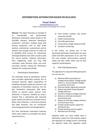
- 1. 1 DISTRIBUTION AUTOMATION BASED ON IEC61850 Nirmal Thaliyil nirmal@kalkitech.com Kalki Communication Technologies Pvt Limited Abstract: This paper illustrates an example of an interoperable and decentralized distribution automation system based on the IEC61850 standard. Advanced distribution automation controllers residing along with primary equipment such as load break switches, sectionalizers, autoreclosers and tie switches have enough resources to make use of IEC61850 ACSE services for information exchanges between each other as well as with the central location. Network information from neighboring nodes can help field controllers make decisions faster and more accurately thereby making the distribution network self- healing and reliable. I. Distribution Automation The challenges faced by Distribution utilities have increased significantly recently, due to increased demand, higher expectations of reliability and power quality by customers and integration of distributed resources into the grid. Distribution Automation (DA) allows utilities to operate power systems more effectively. It improves reliability by using a network that is self-healing with improved power quality and efficiency (reduced losses), better asset utilization, is immune to physical and cyber breaches, and can incorporate more energy generation and storage options. The main distribution automation functions which assist utilities to accomplish the above requirements are a) b) Fault location isolation and service restoration (FLISR) c) Feeder Load balancing d) Volt-VAR optimization e) Conservative voltage reduction (CVR) f) Condition monitoring In this article, we choose one of the elementary Distribution Automation use cases called Volt-VAR optimization to try and find the most suitable communication protocol, media and data model, which may be best suited for standardization. II. Volt-VAR Optimization The objectives for using Volt-VAR optimization as a use case are: a) Minimize kWh consumption at voltages beyond given voltage quality limits (i.e., ensure standard voltages at customer terminals) b) Minimize feeder segment(s) overload c) Reduce load while respecting given voltage tolerance d) Conserve energy via voltage reduction e) Reduce or eliminate overload in transmission lines f) Reduce or eliminate voltage violations on transmission lines g) Provide reactive power support for distribution bus h) Provide spinning reserve support i) Minimize cost of energy Capacitor banks are more widely used in distribution systems for VAR (reactive power) and regulators for voltage control. Controlling the capacitor banks and regulators would
- 2. 2 June 2014 require measurement from single or multiple phases e.g. voltage level, power factor, VAR flow and time of day. The VAR/voltage control devices can be used to switch capacitor banks on/off in order to minimize the reactive power flows on the system and to maintain the bus voltage. III. IEC61850 The IEC61850 communication standard had originally been conceived by TC57 group for substation automation functions. It provides a panoptic view of the power system domain and is now making the object model more comprehensive and more standardized the communication structure. Some of the application areas added are hydro power plants, DER, substation to substation and substation to control center communication and wind power plants. There are also work under progress for adapting the standard for feeder automation, electrical storage, transportation, transferring synchrophasor data etc.. This trend opens up new opportunities for the development of intelligent applications for the power system. IEC61850 has an inherent ability to support more sophisticated automation systems with larger numbers of smart devices. The adoption of 61850 by vendors in their products will provide a standardized information model for each type of vendor product, e.g., relay, capacitor bank, switchgear, etc. The principal benefits of using IEC 61850 for Distribution Automation functions are Object oriented data model Adaptable data exchange rate as per application Peer to peer communication topology Process bus integration Simplified engineering process Enhanced security features IV. Modeling for Volt-VAR control The Shunt capacitor can be modeled as shown in Figure 1. A capacitor bank normally consists of several parallel capacitors per-phase. Therefore each phase has more than one switch logical node XSWI (Circuit Switch) associated with it to engage and disengage capacitors into the circuit. For measurement purposes, there are three instrument transformers TCTR (Current transformer) and TVTR (Voltage Transformer) for each phase. ZCAP (Capacitor bank) logical node represents capacitor bank status such as health, device status, name plate, and operation time. Automatic control logical node AVCO (Automatic Voltage controller) can either be based on local setpoints or setpoints that are received remotely through a communications link from a centralized or peer capacitor controller. Scheduled or set points for a certain range are available for taking necessary actions. Ranges are normally used for voltage, VAR, temperature and current. Voltage regulators with automatic tap changing capabilities allow for controlling the XSWI AVCO CSWI ZCAP MMXU/ MMXN XSWI XSWI XSWI XSWI XSWI TCTR XSWI XSWI TVTR Figure 1: Modelling capacitor bank
- 3. 3 June 2014 voltage according to predefined automatic logic or by remote access through the operator command. Regulators can be modeled as shown in Figure 2. To regulate the voltage of a three-phase three-wire system, banks of single phase regulators can be created. The common schemes are two single-phase voltage regulators connected in an open delta connection, or three single-phase voltage regulators connected in a closed delta. Open- delta configuration requires fewer devices at the cost of a smaller regulation range. Typical regulation range for open delta configuration is ±10% for phases with regulators and ±5% for phase without the regulator. In case of closed delta configuration the range is about ±15% for all phases. ATCC or Automatic Tap Changer Control logical node will control the tap changers. ATCC will have status indication for local operation, operation counter, tap position, parallel/independent operations and block automatic control in addition to controlling operation data and settings and other status information. There may be three or two YLTC (Transformer tap changer) logical nodes in the system as per the scheme explained above. V. Communication Protocols Abstract data models defined in IEC 61850 can be mapped to a number of protocols. Currently, mappings are available for MMS (Manufacturing Message Specification), GOOSE (Generic object oriented substation events) , SMV (Sampled Measured Values) and Web Services. These protocols are usually run over Ethernet links. Mission critical messages that need to be transferred between devices are transferred as GOOSE messages. GOOSE messages are connection less packets that are sent to the network as a multicast message on layer 2 in the OSI model. The router is designed to prevent broadcast and multicast packets from leaving the LAN and only passes IP packets on layer 3. However, this is achieved by attaching a VLAN tag that can be recognized by the router, with each GOOSE message. The router converts GOOSE messages with a VLAN tag into a routable IP packet and sends it to the destination IP. Decentralized automation methods are chosen over centralized methods for higher scalability, better performance and for enabling micro-grid operations. Adoption of IEC61850 for distribution automation application requires transferring GOOSE packets over IP for peer-to-peer communication. Decentralized distribution automation use cases FLISR, VVO (volt-var optimization), CVR require sending measurement and status information between intelligent electronic controllers residing in the field. Protocol Independent Multicast (PIM) used for intra-domain multicast is a bandwidth-conserving technology that reduces traffic by simultaneously delivering a single stream of information to potentially thousands of nodes. Bidirectional PIM variant can be adopted for efficient many-to-many communications within an individual PIM distribution network domain. Although PIM is said to be suitable because of less overhead, MMXU/ MMXN ATCC XSWI XSWI TVTR XSWI XSWI YLTC XSWI XSWI TCTR Figure 2: Modelling Voltage Regulators
- 4. 4 June 2014 there are also other mechanisms to transfer GOOSE packets over IP using layer 2 tunneling protocol, GRE tunneling, MPLS encapsulation and virtual private LAN service encapsulation methods. VI. Communication Technologies As per the IEC61850 standard, the protection class of a distribution network is P1 which means it transfers trip signals in the order of half a cycle i.e. 10ms. For other fast messages, total transmission time shall be less than or equal to 100ms. So it is critical to select the communication technologies which will be able to meet the above specified performance criteria. The assets of distribution utilities are spread across their service territory. In urban areas, the length of the 11kV feeder is typically 3 km and in rural areas, the feeder length may go up to 20km. Wireless solutions have shown the greatest potential for automating distribution networks because they communicate virtually anywhere at a comparatively less investment cost. VII. Conclusion Communication latency, coverage/reach, availability, security, installation, operating and maintenance costs are critical parameters that unremarkably drive the decision-making behind the technology to be used for DA applications. More over out of the above listed communication technologies, only some have the option for peer-to-peer communication using meshing technologies like 802.15.4 and 802.11 mesh. There are standard guideline work in progress like IEEEP1777 to develop the functional, performance, security, and on-site testing requirements for wireless data 802.15.4 Mesh WLAN (802.11s) WLAN (802.11b/g) Cellular/3G/LTE Wimax (802.16 d/e/m) Usage Low data rate Last mile, broadband for rural area LAN & indoor wireless, Backhaul connectivity, internet Broadband internet/ VoIP/ IPTV Frequency range ISM: 868 MHz , 2.4GHz (unlicensed) DSSS 900 MHz, 2.4 GHz, 5.8 GHz (unlicensed) Both ISM and U-NII frequency bands Unlicensed: 2.4 and 5 GHz; DSSS, OFDM GSM 900 MHz, UMTS 1900/2100MHz, GSM 1800 MHz, PCS1900MHz, Cellular 850 MHz 2.3, 2.5, 3.5 GHz licensed bands; 450 MHz, 700 MHz also used Channel Bandwidth 200kHz to 1.2MHz 20/40 MHz for 802.11n 20 MHz for 802.11 a/g 200kHz to 20MHz 20 or 25 MHz (United States) or 28 MHz (Europe) Coverage 50 to 1000 meters as per line of sight Varies with frequency line of sight : 0-15 miles non-line of sight :0-3 miles Indoor: up to 100 m; Outdoor: up to 250 m 3-5 miles (to base station) 3-4 miles Single user data rate 20 to 250 kbps, depending on frequency band As high as 300 Mbps 802.11b: up to 11 Mbps 802.11g/h/j: up to 54 Mbps HSPA+: Up to 28 Mbps, cdma2000/EVDO rev B: Up to 14.7 Mbps Typical 4-16 Mbps Cost Low Moderate Low High Moderate
- 5. 5 June 2014 communication technologies that are to be used in different aspects (types, classes) of power system operations. Whole success of distribution automation depends on communication technology which would be able to cater to above mentioned network constraints which can transfer data over futuristic communication protocol also meeting advanced distribution automation use-cases.