Networking Technologies : Segmentation
•Descargar como PPTX, PDF•
1 recomendación•1,009 vistas

A Presentation for BSIT - USEP STUDENT : By ND ARQUILLANO

Recomendados
Más contenido relacionado
La actualidad más candente
La actualidad más candente (20)
Destacado
Destacado (12)
Similar a Networking Technologies : Segmentation
Similar a Networking Technologies : Segmentation (20)
Último
Último (20)
Networking Technologies : Segmentation
- 1. The history of how Ethernet handles collisions and collision domains dates back to research at the University of Hawaii in 1970. In its attempts to develop a wireless communication system for the islands of Hawaii, university researchers developed a protocol called Aloha. The Ethernet protocol is actually based on the Aloha protocol.
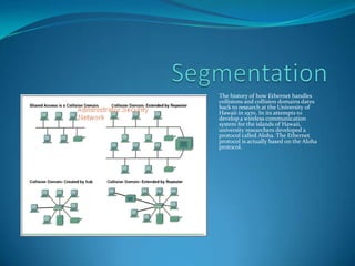
- 2. Segmentation One important skill for a networking professional is the ability to recognize collision domains. Connecting several computers to a single shared-access medium that has no other networking devices attached creates a collision domain. This situation limits the number of computers that can use the medium, also called a segment. Layer 1 devices extend but do not control collision domains. Layer 2 devices segment or divide collision domains. Controlling frame propagation using the MAC address assigned to every Ethernet device performs this function. Layer 2 devices, bridges, and switches, keep track of the MAC addresses and which segment they are on. By doing this these devices can control the flow of traffic at the Layer 2 level. This function makes networks more efficient by allowing data to be transmitted on different segments of the LAN at the same time without the frames colliding. By using bridges and switches, the collision domain is effectively broken up into smaller parts, each becoming its own collision domain. These smaller collision domains will have fewer hosts and less traffic than the original domain. The fewer hosts that exist in a collision domain, the more likely the media will be available. As long as the traffic between bridged segments is not too heavy a bridged network works well. Otherwise, the Layer 2 device can actually slow down communication and become a bottleneck itself. Layer 3 devices, like Layer 2 devices, do not forward collisions. Because of this, the use of Layer 3 devices in a network has the effect of breaking up collision domains into smaller domains. Layer 3 devices perform more functions than just breaking up a collision domain. Layer 3 devices and their functions will be covered in more depth in the section on broadcast domains.
- 3. Layer 2 broadcasts To communicate with all collision domains, protocols use broadcast and multicast frames at Layer 2 of the OSI model. When a node needs to communicate with all hosts on the network, it sends a broadcast frame with a destination MAC address 0xFFFFFFFFFFFF. This is an address to which the network interface card (NIC) of every host must respond.
- 4. Layer 2 Broadcast Layer 2 devices must flood all broadcast and multicast traffic. The accumulation of broadcast and multicast traffic from each device in the network is referred to as broadcast radiation. In some cases, the circulation of broadcast radiation can saturate the network so that there is no bandwidth left for application data. In this case, new network connections cannot be established, and existing connections may be dropped, a situation known as a broadcast storm. The probability of broadcast storms increases as the switched network grows. Because the NIC must interrupt the CPU to process each broadcast or multicast group it belongs to, broadcast radiation affects the performance of hosts in the network. Figure shows the results of tests that Cisco conducted on the effect of broadcast radiation on the CPU performance of a Sun SPARCstation 2 with a standard built-in Ethernet card. As indicated by the results shown, an IP workstation can be effectively shut down by broadcasts flooding the network. Although extreme, broadcast peaks of thousands of broadcasts per second have been observed during broadcast storms. Testing in a controlled environment with a range of broadcasts and multicasts on the network shows measurable system degradation with as few as 100 broadcasts or multicasts per second. Most often, the host does not benefit from processing the broadcast, as it is not the destination being sought. The host does not care about the service that is being advertised, or it already knows about the service. High levels of broadcast radiation can noticeably degrade host performance. The three sources of broadcasts and multicasts in IP networks are workstations, routers, and multicast applications.
- 5. Broadcast domains A broadcast domain is a grouping of collision domains that are connected by Layer 2 devices. Breaking up a LAN into multiple collision domains increases the opportunity for each host in the network to gain access to the media. This effectively reduces the chance of collisions and increases available bandwidth for every host. But broadcasts are forwarded by Layer 2 devices and if excessive, can reduce the efficiency of the entire LAN. Broadcasts have to be controlled at Layer 3, as Layer 2 and Layer 1 devices have no way of controlling them. The total size of a broadcast domain can be identified by looking at all of the collision domains that the same broadcast frame is processed by. In other words, all the nodes that are a part of that network segment bounded by a layer three device. Broadcast domains are controlled at Layer 3 because routers do not forward broadcasts. Routers actually work at Layers 1, 2, and 3. They, like all Layer 1 devices, have a physical connection to, and transmit data onto, the media. They have a Layer 2 encapsulation on all interfaces and perform just like any other Layer 2 device. It is Layer 3 that allows the router to segment broadcast domains.
- 6. Broadcast domains In order for a packet to be forwarded through a router it must have already been processed by a Layer 2 device and the frame information stripped off. Layer 3 forwarding is based on the destination IP address and not the MAC address. For a packet to be forwarded it must contain an IP address that is outside of the range of addresses assigned to the LAN and the router must have a destination to send the specific packet to in its routing table.