
Recomendados
Recomendados
Más contenido relacionado
La actualidad más candente
La actualidad más candente (15)
Similar a 2006 infiniti g35 sedan service repair manual
Similar a 2006 infiniti g35 sedan service repair manual (20)
Más de olfjsekdmmes
Más de olfjsekdmmes (20)
Último
Último (20)
2006 infiniti g35 sedan service repair manual
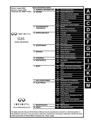
- 1. A B C D E F G H I J K M L QUICK REFERENCE INDEX A GENERAL INFORMATION GI General Information B ENGINE EM Engine Mechanical LU Engine Lubrication System CO Engine Cooling System EC Engine Control System FL Fuel System EX Exhaust System ACC Accelerator Control System C TRANSMISSION/ TRANSAXLE CL Clutch MT Manual Transmission AT Automatic Transmission D DRIVELINE/AXLE TF Transfer PR Propeller Shaft FFD Front Final Drive RFD Rear Final Drive FAX Front Axle RAX Rear Axle E SUSPENSION FSU Front Suspension RSU Rear Suspension WT Road Wheels & Tires F BRAKES BR Brake System PB Parking Brake System BRC Brake Control System G STEERING PS Power Steering System H RESTRAINTS SB Seat Belts SRS Supplemental Restraint System (SRS) I BODY BL Body, Lock & Security System GW Glasses, Window System & Mir- rors RF Roof EI Exterior & Interior IP Instrument Panel SE Seat J AIR CONDITIONER ATC Automatic Air Conditioner K ELECTRICAL SC Starting & Charging System LT Lighting System DI Driver Information System WW Wiper, Washer & Horn BCS Body Control System LAN LAN System AV Audio Visual, Navigation & Tele- phone System ACS Auto Cruise Control System PG Power Supply, Ground & Circuit Ele- ments L MAINTENANCE MA Maintenance M INDEX IDX Alphabetical Index All rights reserved. No part of this Service Manual may be reproduced or stored in a retrieval system, or transmitted in any form, or by any means, electronic, mechanical, recording or otherwise, without the prior written permission of Nissan Motor Company Ltd., Tokyo, Japan. Edition: August 2004 Revision: August 2006 Publication No. SM6E-1V35U3
- 2. This manual contains maintenance and repair procedure for the 2006 INFINITI G35. In order to assure your safety and the efficient functioning of the vehicle, this manual should be read thoroughly. It is especially important that the PRECAUTIONS in the GI section be completely understood before starting any repair task. All information in this manual is based on the latest product information at the time of publication. The right is reserved to make changes in specifi- cations and methods at any time without notice. IMPORTANT SAFETY NOTICE The proper performance of service is essential for both the safety of the technician and the efficient functioning of the vehicle. The service methods in this Service Manual are described in such a manner that the service may be performed safely and accurately. Service varies with the procedures used, the skills of the technician and the tools and parts available. Accordingly, anyone using service procedures, tools or parts which are not specifically recommended by NISSAN must first be completely satisfied that neither personal safety nor the vehicle’s safety will be jeopardized by the service method selected.
- 3. QUICK REFERENCE CHART G35 QUICK REFERENCE CHART G35 PFP:00000 ENGINE TUNE-UP DATA (VQ35DE) ELS0003W Engine model VQ35DE Firing order 1-2-3-4-5-6 Idle speed A/T (In “N” position) M/T rpm 650 ± 50 Ignition timing (BTDC at idle speed) 15° ± 5° CO% at idle 0.7 - 9.9 % and engine runs smoothly Drive Belt Deflection adjustment Unit: mm (in) Tension adjustment Unit: N (kg, Ib) Used belt New belt Used belt New belt Limit After adjustment Limit After adjustment Alternator and power steering oil pump belt 7 (0.28) 4 - 5 (0.16 - 0.20) 3.5 - 4.5 (0.138 - 0.177) 294 (30, 66) 730 - 818 (74.5 - 83.5, 164 - 184) 838 - 926 (85.5 - 94.5, 188 - 208) A/C compressor belt 12 (0.47) 9 - 10 (0.35 - 0.39) 8 - 9 (0.31 - 0.35) 196 (20, 44) 348 - 436 (35.5 - 44.5, 78 - 98) 470 - 559 (48 - 57, 106 - 126) Applied pushing force 98 N (10 kg, 22 lb) — Radiater cap relief pressure kPa (kg/cm2 , psi) 78 - 98 (0.8 - 1.0, 11 - 14) Standard Limit 59 (0.6, 9) Cooling system leakage testing pres- sure kPa (kg/cm2 , psi) 157 (1.6, 23) Compression pressure kPa (kg/cm2 , psi)/ rpm 1,270 (13.0, 184)/300 Standard Minimum 980 (10.0, 142)/300 Differential limit between cylinders 100 (1.0, 15)/300 Spark plug (Platinum-tipped type) Make NGK Standard type PLFR5A-11 Hot type PLFR4A-11 Cold type PLFR6A-11 Gap (Nominal) mm(in) 1.1 (0.043) 2006
- 4. QUICK REFERENCE CHART G35 FRONT WHEEL ALIGNMENT (Unladen* ) ELS0003X *: Fuel, engine coolant and lubricant are full. Spare tire, jack, hand tools and mats are in designated positions. *: Fuel, engine coolant and lubricant are full. Spare tire, jack, hand tools and mats are in designated positions. REAR WHEEL ALIGNMENT (Unladen*) ELS0003Y *: Fuel, engine coolant and lubricant are full. Spare tire, jack, hand tools and mats are in designated positions. AXLE 2WD AWD Camber Degree minute (Decimal degree) Minimum –0°50′ (–0.83°) –1°00′ (–1.00°) Nominal –0°05′ (–0.08°) –0°15′ (–0.25°) Maximum 0°40′ (0.67°) 0°30′ (0.50°) Left and right differ- ence 45′ (0.75°) 45′ (0.75°) Caster Degree minute (Decimal degree) Minimum 7°00′ (7.00°) 5°55′ (5.92°) Nominal 7°45′ (7.75°) 6°40′ (6.67°) Maximum 8°30′ (8.50°) 7°25′ (7.42°) Left and right differ- ence 45′ (0.75°) 45′ (0.75°) Kingpin inclination Degree minute (Decimal degree) Minimum 3°45′ (3.75°) 5°15′ (5.25°) Nominal 4°30′ (4.50°) 6°00′ (6.00°) Maximum 5°15′ (5.25°) 6°45′ (6.75°) Total toe-in Distance Minimum 0 mm (0 in) 0 mm (0 in) Nominal 1 mm (0.04 in) 1 mm (0.04 in) Maximum 2 mm (0.08 in) 2 mm (0.08 in) Angle (left wheel or right wheel) Degree minute (Decimal degree) Minimum 0°00′ (0.00°) 0°00′ (0.00°) Nominal 0°02′30″ (0.04°) 0°02′30″ (0.04°) Maximum 0°05′ (0.08°) 0°05′ (0.08°) AXLE 2WD AWD Tire 18 inch Except 18 inch Wheel turning angle (Full turn) Inner Minimum 35° 35′ (35.6°) 37° 30′ (37.5°) 38° 00′ (38.0°) Degree minute (Decimal degree) Nominal 38° 35′ (38.6°) 40° 30′ (40.5°) 41° 00′ (41.0°) Maximum 39° 35′ (39.6°) 41° 30′ (41.5°) 42° 00′ (42.0°) Outter Nominal 31° 00′ (31.0°) 32° 30′ (32.5°) 31° 40′ (31.7°) Degree minute (Decimal degree) Camber Degree minute (Decimal degree) Minimum –1°05′ (–1.08°) Nominal –0°35′ (–0.58°) Maximum –0°05′ (–0.08°) Left and right difference 45′ (0.75°) Total toe-in Distance Minimum 0.1 mm (0.004 in) Nominal 2.8 mm (0.110 in) Maximum 5.5 mm (0.217 in) Angle (left wheel or right wheel) Degree minute (Decimal degree) Minimum 0°00′ (0.00°) Nominal 0°07′ (0.12°) Maximum 0°14′ (0.23°) 2006
- 5. QUICK REFERENCE CHART G35 BRAKE ELS0003Z Unit : mm ( in ) * : Under a force of 490 N( 50 kg, 110 lb ) with the engine running. REFILL CAPACITIES ELS00040 AXLE 2WD AWD Front brake Pad repair limit thickness 2.0 (0.079) Rotor repair limit thickness 26.0 (1.024) Rear brake Pad repair limit thickness 2.0 (0.079) Rotor rrepair limit thickness 14.0 (0.551) Brake pedal free height M/T model 153.2 - 163.2 (6.03 - 6.43) A/T model 161.5 - 171.5 (6.36 - 6.75) Brake pedal depressed height* M/T model More than 90 (3.54) A/T model More than 95 (3.74) UNIT Liter US measure Fuel tank 76 20 gal Engine Coolant ( With reservoir tank ) at MAX level 8.7 9-1/4 qt Engine oil Drain and refill With oil filter change 4.7 5 qt Without oil filter change 4.4 4-5/8 qt Dry engine (Overhaul) 5.4 5-3/4 qt Transmission A/T 10.3 10-7/8 qt M/T 2.9 3-1/8 qt Transfer 1.25 2-5/8 pt Differential carrier Front 0.65 1-3/8 pt Rear 1.4 3 pt Power steering system 1.0 1-1/8 qt Air conditioning system Compressor oil 0.18 6.0 fl oz Refrigerant 0.55 kg 1.21 lb 2006
- 6. GI-1 GENERAL INFORMATION A GENERAL INFORMATION CONTENTS C D E F G H I J K L M B GI SECTION GI Revision: 2006 August 2006 G35 Sedan GENERAL INFORMATION PRECAUTIONS ..................................................... ..... 3 Description .......................................................... ..... 3 Precautions for Supplemental Restraint System (SRS) “AIR BAG” and “SEAT BELT PRE-TEN- SIONER” ............................................................. ..... 3 PrecautionsNecessaryforSteeringWheelRotation After Battery Disconnect ..................................... ..... 3 OPERATION PROCEDURE ............................ ..... 3 Precautions for NVIS/IVIS (NISSAN/INFINITI VEHICLE IMMOBILIZER SYSTEM - NATS) (If Equipped) ............................................................ ..... 4 General Precautions ........................................... ..... 4 Precautions for Three Way Catalyst .................... ..... 6 Precautions for Fuel of Automatic Transmission Models (Unleaded Premium Gasoline Recom- mended) .............................................................. ..... 6 Precautions for Fuel of Manual Transmission Mod- els (Unleaded Premium Gasoline Required) ....... ..... 6 Precautions for Multiport Fuel Injection System or Engine Control System ....................................... ..... 7 Precautions for Hoses ......................................... ..... 7 HOSE REMOVAL AND INSTALLATION .......... ..... 7 HOSE CLAMPING ........................................... ..... 7 Precautions for Engine Oils ................................. ..... 8 HEALTH PROTECTION PRECAUTIONS ........ ..... 8 Precautions for Air Conditioning .......................... ..... 8 HOW TO USE THIS MANUAL .............................. ..... 9 Description .......................................................... ..... 9 Terms .................................................................. ..... 9 Units .................................................................... ..... 9 Contents .............................................................. ..... 9 Components ........................................................ ... 10 SYMBOLS ........................................................ ... 10 How to Follow Trouble Diagnoses ....................... ....11 DESCRIPTION ................................................. ....11 HOW TO FOLLOW TEST GROUPS IN TROU- BLE DIAGNOSES ............................................ ....11 HARNESS WIRE COLOR AND CONNECTOR NUMBER INDICATION .................................... ... 12 KEY TO SYMBOLS SIGNIFYING MEASURE- MENTS OR PROCEDURES ............................ ... 13 How to Read Wiring Diagrams ............................ ... 15 CONNECTOR SYMBOLS ................................ ... 15 SAMPLE/WIRING DIAGRAM - EXAMPL - ....... ... 16 DESCRIPTION ................................................. ... 17 Abbreviations ....................................................... ... 23 SERVICEINFORMATIONFORELECTRICALINCI- DENT ...................................................................... ... 24 How to Check Terminal ........................................ ... 24 CONNECTOR AND TERMINAL PIN KIT ......... ... 24 HOW TO PROBE CONNECTORS ................... ... 24 Howto Perform Efficient Diagnosis foran Electrical Incident ................................................................ ... 27 WORK FLOW ................................................... ... 27 INCIDENT SIMULATION TESTS ..................... ... 27 CIRCUIT INSPECTION .................................... ... 30 Control Units and Electrical Parts ........................ ... 35 PRECAUTIONS ............................................... ... 35 CONSULT-II CHECKING SYSTEM ....................... ... 37 Description ........................................................... ... 37 Function and System Application ........................ ... 37 Nickel Metal Hydride Battery Replacement ......... ... 37 Checking Equipment ........................................... ... 38 CONSULT-II Start Procedure ............................... ... 38 CONSULT-II Data Link Connector (DLC) Circuit . ... 39 INSPECTION PROCEDURE ........................... ... 39 CIRCUIT DIAGRAM ......................................... ... 40 LIFTING POINT ...................................................... ... 41 Commercial Service Tools ................................... ... 41 Garage Jack and Safety Stand ............................ ... 41 2-Pole Lift ............................................................ ... 42 Board-On Lift ....................................................... ... 43 TOW TRUCK TOWING .......................................... ... 44 Tow Truck Towing ................................................ ... 44 TWO WHEEL DRIVE MODELS ....................... ... 44 ALL WHEEL DRIVE MODELS ......................... ... 45 Vehicle Recovery (Freeing a Stuck Vehicle) ........ ... 45 FRONT ............................................................. ... 45 REAR ............................................................... ... 45
- 7. GI-2 Revision: 2006 August 2006 G35 Sedan TIGHTENING TORQUE OF STANDARD BOLTS . ... 46 Tightening Torque Table ...................................... ... 46 RECOMMENDED CHEMICAL PRODUCTS AND SEALANTS ............................................................ ... 47 Recommended Chemical Products and Sealants... 47 IDENTIFICATION INFORMATION ......................... ... 48 Model Variation .................................................... ... 48 IDENTIFICATION NUMBER ............................. ... 49 IDENTIFICATION PLATE ................................. ...49 ENGINE SERIAL NUMBER .............................. ...50 AUTOMATIC TRANSMISSION NUMBER ........ ...50 MANUAL TRANSMISSION NUMBER .............. ...50 Dimensions .......................................................... ...51 Wheels & Tires ..................................................... ...51 TERMINOLOGY ..................................................... ...52 SAE J1930 Terminology List ................................ ...52
- 8. PRECAUTIONS GI-3 C D E F G H I J K L M B GI Revision: 2006 August 2006 G35 Sedan PRECAUTIONS PFP:00001 Description NAS0002C Observe the following precautions to ensure safe and proper servicing. These precautions are not described in each individual section. Precautions for Supplemental Restraint System (SRS) “AIR BAG” and “SEAT BELT PRE-TENSIONER” NAS0002D The Supplemental Restraint System such as “AIR BAG” and “SEAT BELT PRE-TENSIONER”, used along with a front seat belt, helps to reduce the risk or severity of injury to the driver and front passenger for certain types of collision. This system includes seat belt switch inputs and dual stage front air bag modules. The SRS system uses the seat belt switches to determine the front air bag deployment, and may only deploy one front air bag, depending on the severity of a collision and whether the front occupants are belted or unbelted. Information necessary to service the system safely is included in the SRS and SB section of this Service Man- ual. WARNING: ● To avoid rendering the SRS inoperative, which could increase the risk of personal injury or death in the event of a collision which would result in air bag inflation, all maintenance must be per- formed by an authorized NISSAN/INFINITI dealer. ● Improper maintenance, including incorrect removal and installation of the SRS, can lead to per- sonal injury caused by unintentional activation of the system. For removal of Spiral Cable and Air Bag Module, see the SRS section. ● Do not use electrical test equipment on any circuit related to the SRS unless instructed to in this Service Manual. SRS wiring harnesses can be identified by yellow and/or orange harnesses or harness connectors. Precautions Necessary for Steering Wheel Rotation After Battery Disconnect NAS0002E NOTE: ● This Procedure is applied only to models with Intelligent Key system and NVIS/IVIS (NISSAN/INFINITI VEHICLE IMMOBILIZER SYSTEM - NATS). ● Remove and install all control units after disconnecting both battery cables with the ignition knob in the ″LOCK″ position. ● Always use CONSULT-II to perform self-diagnosis as a part of each function inspection after finishing work. If DTC is detected, perform trouble diagnosis according to self-diagnostic results. For models equipped with the Intelligent Key system and NVIS/IVIS, an electrically controlled steering lock mechanism is adopted on the key cylinder. For this reason, if the battery is disconnected or if the battery is discharged, the steering wheel will lock and steering wheel rotation will become impossible. If steering wheel rotation is required when battery power is interrupted, follow the procedure below before starting the repair operation. OPERATION PROCEDURE 1. Connect both battery cables. NOTE: Supply power using jumper cables if battery is discharged. 2. Use the Intelligent Key or mechanical key to turn the ignition switch to the ″ACC″ position. At this time, the steering lock will be released. 3. Disconnect both battery cables. The steering lock will remain released and the steering wheel can be rotated. 4. Perform the necessary repair operation. 5. When the repair work is completed, return the ignition switch to the ″LOCK″ position before connecting the battery cables. (At this time, the steering lock mechanism will engage.) 6. Perform a self-diagnosis check of all control units using CONSULT-II.
- 9. GI-4 PRECAUTIONS Revision: 2006 August 2006 G35 Sedan Precautions for NVIS/IVIS (NISSAN/INFINITI VEHICLE IMMOBILIZER SYSTEM - NATS) (If Equipped) NAS0002F NVIS/IVIS (NATS) will immobilize the engine if someone tries to start it without the registered key of NVIS/IVIS (NATS). Both of the originally supplied ignition key IDs have been NVIS/IVIS (NATS) registered. The security indicator is located on the instrument panel. The indicator blinks when the immobilizer system is functioning. Therefore, NVIS/IVIS (NATS) warns outsiders that the vehicle is equipped with the anti-theft system. ● When NVIS/IVIS (NATS) detects trouble, the security indicator lamp lights up while ignition switch is in "ON" position. This lighting up indicates that the anti-theft is not functioning, so prompt service is required. ● When servicing NVIS/IVIS (NATS) (trouble diagnoses, system initialization and additional registration of other NVIS/IVIS (NATS) ignition key IDs), CONSULT-II hardware and CONSULT-II NVIS/IVIS (NATS) software is necessary. Regarding the procedures of NVIS/IVIS (NATS) initialization and NVIS/IVIS (NATS) ignition key ID regis- tration, refer to CONSULT-II operation manual, NVIS/IVIS (NATS). Therefore, CONSULT-II NVIS/IVIS (NATS) software (program card and operation manual) must be kept strictly confidential to maintain the integrity of the anti-theft function. ● When servicing NVIS/IVIS (NATS) (trouble diagnoses, system initialization and additional registration of other NVIS/IVIS (NATS) ignition key IDs), it may be necessary to re-register original key identification. Therefore, be sure to receive all keys from vehicle owner. A maximum of four or five key IDs can be regis- tered into NVIS/IVIS (NATS). ● When failing to start the engine first time using the key of NVIS/IVIS (NATS), start as follows. 1. Leave the ignition key in "ON" position for approximately 5 seconds. 2. Turn ignition key to "OFF" or "LOCK" position and wait approximately 5 seconds. 3. Repeat step 1 and 2 again. 4. Restart the engine while keeping the key separate from any others on key-chain. General Precautions NAS0002G ● Do not operate the engine for an extended period of time without proper exhaust ventilation. Keep the work area well ventilated and free of any flammable materials. Special care should be taken when handling any flam- mable or poisonous materials, such as gasoline, refrigerant gas, etc. When working in a pit or other enclosed area, be sure to properly ventilate the area before working with hazardous mate- rials. Do not smoke while working on the vehicle. ● Before jacking up the vehicle, apply wheel chocks or other tire blocks to the wheels to prevent the vehicle from moving. After jacking up the vehicle, support the vehicle weight with safety stands at the points designated for proper lifting before working on the vehicle. These operations should be done on a level surface. ● When removing a heavy component such as the engine or tran- saxle/transmission, be careful not to lose your balance and drop them. Also, do not allow them to strike adjacent parts, especially the brake tubes and master cylinder. SGI285 SGI231
- 10. PRECAUTIONS GI-5 C D E F G H I J K L M B GI Revision: 2006 August 2006 G35 Sedan ● Before starting repairs which do not require battery power: Turn off ignition switch. Disconnect the negative battery terminal. ● If the battery terminals are disconnected, recorded memory of radio and each control unit is erased. ● Battery posts, terminals and related accessories contain lead and lead compounds. Wash hands after handling. ● To prevent serious burns: Avoid contact with hot metal parts. Do not remove the radiator cap when the engine is hot. ● Dispose of or recycle drained oil or the solvent used for cleaning parts in an appropriate manner. ● Do not attempt to top off the fuel tank after the fuel pump nozzle shuts off automatically. Continued refueling may cause fuel overflow, resulting in fuel spray and possibly a fire. ● Clean all disassembled parts in the designated liquid or solvent prior to inspection or assembly. ● Replace oil seals, gaskets, packings, O-rings, locking washers, cotter pins, self-locking nuts, etc. with new ones. ● Replace inner and outer races of tapered roller bearings and needle bearings as a set. ● Arrange the disassembled parts in accordance with their assembled locations and sequence. ● Do not touch the terminals of electrical components which use microcomputers (such as ECM). Static electricity may damage internal electronic components. ● After disconnecting vacuum or air hoses, attach a tag to indicate the proper connection. ● Use only the fluids and lubricants specified in this manual. ● Use approved bonding agent, sealants or their equivalents when required. ● Use hand tools, power tools (disassembly only) and recom- mended special tools where specified for safe and efficient ser- vice repairs. ● When repairing the fuel, oil, water, vacuum or exhaust systems, check all affected lines for leaks. ● Before servicing the vehicle: Protect fenders, upholstery and carpeting with appropriate cov- ers. Take caution that keys, buckles or buttons do not scratch paint. SEF289H SGI233 PBIC0190E SGI234
- 11. GI-6 PRECAUTIONS Revision: 2006 August 2006 G35 Sedan WARNING: To prevent ECM from storing the diagnostic trouble codes, do not carelessly disconnect the harness connectors which are related to the engine control system and TCM (transmission control module) system. The connectors should be disconnected only when working according to the WORK FLOW of TROUBLE DIAGNOSES in EC and AT sections. Precautions for Three Way Catalyst NAS0002H If a large amount of unburned fuel flows into the catalyst, the catalyst temperature will be excessively high. To prevent this, follow the instructions. ● Use unleaded gasoline only. Leaded gasoline will seriously damage the three way catalyst. ● When checking for ignition spark or measuring engine compression, make tests quickly and only when necessary. ● Do not run engine when the fuel tank level is low, otherwise the engine may misfire, causing damage to the catalyst. Do not place the vehicle on flammable material. Keep flammable material off the exhaust pipe and the three way catalyst. Precautions for Fuel of Automatic Transmission Models (Unleaded Premium Gasoline Recommended) NAS0002I Use unleaded regular gasoline with an octane rating of at least 87 AKI (Anti-Knock Index) number (Research octane number 91). For improved vehicle performance, NISSAN/INFINITI recommend the use of unleaded premium gasoline with an octane rating of at least 91 AKI number (Research octane number 96). CAUTION: Do not use leaded gasoline. Using leaded gasoline will damage the three way catalyst. Do not use E- 85fuel (85% fuel ethanol, 15% unleaded gasoline) unless the vehicle is specifically designed for E-854 fuel (i.e. Flexible Fuel Vehicle - FFV models). Using a fuel other than that specified could adversely affect the emission control devices and systems, and could also affect the warranty coverage validity. Precautions for Fuel of Manual Transmission Models (Unleaded Premium Gaso- line Required) NAS0002J Use unleaded premium gasoline with an octane rating of at least 91 AKI (Anti-Knock Index) number (Research octane number 96). If unleaded premium gasoline is not available, unleaded regular gasoline with an octane rating of at least 87 AKI number (Research octane number 91) can be used, but only under the following precautions: ● have the fuel tank filled only partially with unleaded regular gasoline, and fill up with unleaded premium gasoline as soon as possible. ● avoid full throttle driving and abrupt acceleration. However, for maximum vehicle performance, the use of unleaded premium gasoline is recommended. CAUTION: Do not use leaded gasoline. Using leaded gasoline will damage the three way catalyst. Do not use E-85 fuel (85% fuel ethanol, 15% unleaded gasoline) unless the vehicle is specifically designed for E-85 fuel (i.e. Flexible Fuel Vehicle - FFV models). Using a fuel other than that specified could adversely affect the emission control devices and systems, and could also affect the warranty coverage validity.
- 12. PRECAUTIONS GI-7 C D E F G H I J K L M B GI Revision: 2006 August 2006 G35 Sedan Precautions for Multiport Fuel Injection System or Engine Control System NAS0002K ● Before connecting or disconnecting any harness connector for the multiport fuel injection system or ECM: Turn ignition switch to “OFF” position. Disconnect negative battery terminal. Otherwise, there may be damage to ECM. ● Before disconnecting pressurized fuel line from fuel pump to injectors, be sure to release fuel pressure. ● Be careful not to jar components such as ECM and mass air flow sensor. Precautions for Hoses NAS0002L HOSE REMOVAL AND INSTALLATION ● To prevent damage to rubber hose, do not pry off rubber hose with tapered tool or screwdriver. ● To reinstall the rubber hose securely, make sure that hose inser- tion length and orientation is correct. (If tube is equipped with hose stopper, insert rubber hose into tube until it butts up against hose stopper.) HOSE CLAMPING ● If old rubber hose is re-used, install hose clamp in its original position (at the indentation where the old clamp was). If there is a trace of tube bulging left on the old rubber hose, align rubber hose at that position. ● Discard old clamps; replace with new ones. SGI787 SMA019D SMA020D SMA021D
- 13. Thank you very much for your reading. Please Click Here. Then Get COMPLETE MANUAL. NO WAITING NOTE: If there is no response to click on the link above, please download the PDF document first and then click on it.
- 14. GI-8 PRECAUTIONS Revision: 2006 August 2006 G35 Sedan ● After installing plate clamps, apply force to them in the direction of the arrow, tightening rubber hose equally all around. Precautions for Engine Oils NAS0002M Prolonged and repeated contact with used engine oil may cause skin cancer. Try to avoid direct skin contact with used oil. If skin contact is made, wash thoroughly with soap or hand cleaner as soon as possible. HEALTH PROTECTION PRECAUTIONS ● Avoid prolonged and repeated contact with oils, particularly used engine oils. ● Wear protective clothing, including impervious gloves where practicable. ● Do not put oily rags in pockets. ● Avoid contaminating clothes, particularly underpants, with oil. ● Heavily soiled clothing and oil-impregnated footwear should not be worn. Overalls must be cleaned regu- larly. ● First aid treatment should be obtained immediately for open cuts and wounds. ● Use barrier creams, applying them before each work period, to help the removal of oil from the skin. ● Wash with soap and water to ensure all oil is removed (skin cleansers and nail brushes will help). Prepa- rations containing lanolin replace the natural skin oils which have been removed. ● Do not use gasoline, kerosene, diesel fuel, gas oil, thinners or solvents for cleaning skin. ● If skin disorders develop, obtain medical advice without delay. ● Where practical, degrease components prior to handling. ● Where there is a risk of eye contact, eye protection should be worn, for example, chemical goggles or face shields; in addition an eye wash facility should be provided. Precautions for Air Conditioning NAS0002N Use an approved refrigerant recovery unit any time the air conditioning system must be discharged. Refer to ATC/MTC section “HFC-134a (R-134a) Service Procedure”, “REFRIGERANT LINES” for specific instructions. SMA022D
- 15. HOW TO USE THIS MANUAL GI-9 C D E F G H I J K L M B GI Revision: 2006 August 2006 G35 Sedan HOW TO USE THIS MANUAL PFP:00008 Description NAS0002O This volume explains “Removal, Disassembly, Installation, Inspection and Adjustment” and “Trouble Diag- noses”. Terms NAS0002P ● The captions WARNING and CAUTION warn you of steps that must be followed to prevent personal injury and/or damage to some part of the vehicle. WARNING indicates the possibility of personal injury if instructions are not followed. CAUTION indicates the possibility of component damage if instructions are not followed. BOLD TYPED STATEMENTS except WARNING and CAUTION give you helpful information. Standard value:Tolerance at inspection and adjustment. Limit value:The maximum or minimum limit value that should not be exceeded at inspection and adjust- ment. Units NAS0002Q ● The UNITS given in this manual are primarily expressed as the SI UNIT (International System of Unit), and alternatively expressed in the metric system and in the yard/pound system. Also with regard to tightening torque of bolts and nuts, there are descriptions both about range and about the standard tightening torque. “Example” Range Standard Contents NAS0002R ● ALPHABETICAL INDEX is provided at the end of this manual so that you can rapidly find the item and page you are searching for. ● A QUICK REFERENCE INDEX, a black tab (e.g. ) is provided on the first page. You can quickly find the first page of each section by matching it to the section's black tab. ● THE CONTENTS are listed on the first page of each section. ● THE TITLE is indicated on the upper portion of each page and shows the part or system. ● THE PAGE NUMBER of each section consists of two or three letters which designate the particular sec- tion and a number (e.g. “BR-5”). ● THE SMALL ILLUSTRATIONS show the important steps such as inspection, use of special tools, knacks of work and hidden or tricky steps which are not shown in the previous large illustrations. Assembly, inspection and adjustment procedures for the complicated units such as the automatic tran- saxle or transmission, etc. are presented in a step-by-step format where necessary. Outer Socket Lock Nut : 59 - 78 N·m (6.0 - 8.0 kg-m, 43 - 58 ft-lb) Drive Shaft Installation Bolt : 44.3 N·m (4.5 kg-m, 33 ft-lb)
- 16. GI-10 HOW TO USE THIS MANUAL Revision: 2006 August 2006 G35 Sedan Components NAS0002S ● THE LARGE ILLUSTRATIONS are exploded views (see the following) and contain tightening torques, lubrication points, section number of the PARTS CATALOG (e.g. SEC. 440) and other information neces- sary to perform repairs. The illustrations should be used in reference to service matters only. When ordering parts, refer to the appropriate PARTS CATALOG . Components shown in an illustration may be identified by a circled number. When this style of illustration is used, the text description of the components will follow the illustration. SYMBOLS 1. Union bolt 2. Copper washer 3. Brake hose 4. Cap 5. Bleed valve 6. Sliding pin bolt 7. Piston seal 8. Piston 9. Piston boot 10. Cylinder body 11. Sliding pin 12. Torque member mounting bolt 13. Washer 14. Sliding pin boot 15. Bushing 16. Torque member 17. Inner shim cover 18. Inner shim 19. Inner pad 20. Pad retainer 21. Pad wear sensor 22. Outer pad 23. Outer shim 24. Outer shim cover 1: PBC (Poly Butyl Cuprysil) grease or silicone-based grease 2: Rubber grease : Brake fluid Refer to GI section for additional symbol definitions. SFIA2959E SAIA0749E
- 17. HOW TO USE THIS MANUAL GI-11 C D E F G H I J K L M B GI Revision: 2006 August 2006 G35 Sedan How to Follow Trouble Diagnoses NAS0002T DESCRIPTION NOTICE: Trouble diagnoses indicate work procedures required to diagnose problems effectively. Observe the following instructions before diagnosing. 1. Before performing trouble diagnoses, read the “Preliminary Check”, the “Symptom Chart” or the “Work Flow”. 2. After repairs, re-check that the problem has been completely eliminated. 3. Refer to Component Parts and Harness Connector Location for the Systems described in each section for identification/location of components and harness connectors. 4. Refer to the Circuit Diagram for quick pinpoint check. If you need to check circuit continuity between harness connectors in more detail, such as when a sub-harness is used, refer to Wiring Diagram in each individual section and Harness Layout in PG section for identification of harness connectors. 5. When checking circuit continuity, ignition switch should be OFF. 6. Before checking voltage at connectors, check battery voltage. 7. After accomplishing the Diagnostic Procedures and Electrical Components Inspection, make sure that all harness connectors are reconnected as they were. HOW TO FOLLOW TEST GROUPS IN TROUBLE DIAGNOSES 1. Work and diagnostic procedure Start to diagnose a problem using procedures indicated in enclosed test groups. 2. Questions and required results Questions and required results are indicated in bold type in test group. The meaning of are as follows: SAIA0256E