SlideShare una empresa de Scribd logo
1 de 26
Descargar para leer sin conexión
EE DEPT. ,SSCE 1
CHAPTER 1
1. INTRODUCTION
The 220kv GSS Madri, Udaipur is a grid of Rajasthan vidhyut vitran Nigam limited
(RVVNL). This grid substation is main supplier of electricity in Udaipur district. The total grid
capacity is 200MVA.
Government of Rajasthan on 19th July 2000, issued a gazette notification unbundling
Rajasthan State Electricity Board into Rajasthan Rajya Vidyut Utpadan Nigam Ltd., which will
be the generation Company; Rajasthan Rajya Vidyut Prasaran Nigam Ltd., which will be the
transmission Company and the three regional distribution companies namely Jaipur Vidyut
Vitran Nigam Ltd., ; Ajmer Vidyut Vitran Nigam Ltd. and Jodhpur Vidyut Vitran Nigam
Limited.
Fig. No. (1.1) location of GSS
.
EE DEPT. ,SSCE 2
CHAPTER 2
2. INCOMMING AND OUTGOING LINES OF MADRI
Table No. (2.1) Incoming and Outgoing
INCOMING
LINES 220KV
OUTGOING LINES
220 KV
INCOMING
LINES
132KV
OUTGOING
LINES 132 KV
OUTGOING
LINES
33KV
1.DEBARI 1.BANSWARA 1.DEBARI 1.DEBARI 1.HIRAN
MAGRI,SEC-4-
1
2.ZAWAR MINES 2.ZAWAR MINES 2.HIRAN
MAGRI,SEC-4-
2
3.PRATAP
NAGAR
3.PRATAPNAGA
R
3.SAVINA-1
4.RSMM 4.SAVINA-2
5.RELIANCE
CHEMOTEX
5.MIA-1
6.MIA-2
7.MATOON-1
8.MATOON-2
EE DEPT. ,SSCE 3
CHAPTER 3
3. TRANSFORMERS
3.1 DEFINATION:
Transformer is a static device by means of which electric power in one circuit is transformed
into electric power of same frequency in another circuit.
3.2 Transformers used in GSS:
Fig. No. (3.1) 220/132 KV, 100 MVA Transformer
Fig. No. (3.2) 132/33 KV40/50 MVA Transformer
EE DEPT. ,SSCE 4
Fig. No. (3.3) 132/33 KV20/25 MVA Transformer
3.3 Transformer parts:
Core:
In an electrical power transformer, there are primary, secondary and may be tertiary windings.
The performance of a transformer mainly depends upon the flux linkages between these
windings. For efficient flux linking between these windings, one low reluctance magnetic path
common to all windings should be provided in the transformer.
Windings:
The windings consist of the current-carrying conductors wound around the sections of the
core, and these must be properly insulated, supported and cooled to withstand operational and
test conditions.
Conservator tank:
This is a cylindrical tank mounted on supporting structure on the roof the transformer main
tank. The main function of conservator tank of transformer is to provide adequate space for
expansion of oil inside the transformer.
Fig. No. (3.4) Conservator tank
EE DEPT. ,SSCE 5
Breather:
Whenever electrical power transformer is loaded, the temperature of the transformer insulating
oil increases, consequently the volume of the oil is increased. As the volume of the oil is
increased, the air above the oil level in conservator will come out.. The natural air always
consists of more or less moisture in it and this moisture can be mixed up with oil if it is allowed
to enter into the transformer
Fig. No. (3.5) Breather:
Cooling equipment:
The radiator of transformer accelerates the cooling rate of transformer. Thus, it plays a vital
role in increasing loading capacity of an electrical transformer. This is basic function of radiator
of an electrical power transformer.
Fig. No. (3.6) Cooling equipment:
EE DEPT. ,SSCE 6
CHAPTER 4
4. EARTHING
The Earthing is of two principal types viz.
 Neutral Earthing and
 Equipment Body Earthing
The neutral point of star-connected 3-phase winding of power transformers is connected to
low resistance ground, such a connection is called 'Neutral grounding'. It gives advantages of
stable neutral point, relatively simple earth fault relaying, discharge of over-voltages to earth
due to lightning, control over earth fault current etc.
SPECEFICATION OF TRANSFORMER:
Fig. No. (4.1) 40/50 MVA Transformer
Fig. No. (4.2) 100 MVA Transformer:
EE DEPT. ,SSCE 7
CHAPTER 5
5. SWITCH YARD
5.1 Single line diagram (SLD):
Fig. No. (5.1) Single line diagram
EE DEPT. ,SSCE 8
5.2 YARD VIEW OF 220/132KV
Fig. No. (5.2) YARD VIEW OF 220/132KV
5.3 EQUIPMENT
ISOLATOR
Fig. No. (5.3) Isolators
5.4 LIGHTENING ARRESTOR
A surge arrester or lightning arrester is a device connected between line and earth, i.e., in
parallel with the equipment to be protected at the substation. It limits the magnitude of
lightning and switching over voltages at the substation and provides a low resistance path for
the surge current to flow to the ground.
EE DEPT. ,SSCE 9
Fig. No. (5.4) LIGHTENING ARRESTOR
5.6 CIRCUIT BREAKERS
SF6 Circuit Breaker:
SF6 is a heavy chemically inert nontoxic noninflammable gas. Its other
properties, which make it ideal for circuit breaking, are:
 At atmospheric pressure its dielectric strength is two to three times that of air.
Because of excellent insulating properties of the gas, reduced electrical clearances
are needed.
 Its heat transferability at atmospheric pressure is 2 to 2.5 times that of air; therefore
smaller conductor sizes needed.
Fig. No. (5.5) SF6 Circuit Breaker
EE DEPT. ,SSCE 10
Advantage of SF6 Circuit Breaker
 Low gas velocity and pressure employed prevent current chopping; capacity currents
are interrupted without restriking.
 There is no exhaust of high pressure gas to atmosphere, and their operation is silent.
 No carbon deposition takes place and as such, there is no insulation tracking.
 The smaller size of conductor and clearances lead to small overall breaker size; and
these have ample overload margin.
VACUUM CIRCUIT BREAKER:
In such breakers vacuum is used as the arc quenching medium. Since vacuum offer the highest
insulating strength. It has for superior arc quenching properties than any other medium.
Fig. No. (5.6) VACUUM CIRCUIT BREAKER
5.7 INSTRUMENT TRANSFORMER:
CURRENT TRANSFORMER:
These instrument transformers are connected in AC power circuits to feed the current coils of
indicating and metering instruments (ammeter, wattmeter’s, and watt hour meters) and
protective relays. Thus the CTs Borden the limits of measurements and maintain a watch over
the currents flowing in the circuit and over the power loads. In high voltage installation CTs in
addition to above, also isolate the indicating and metering instruments from high voltage. The
current transformer basically consists of an iron core on which are wound a primary and one
or two secondary windings
EE DEPT. ,SSCE 11
Fig. No. (5.7) CURRENT TRANSFORMER:
SPECIFICATION OF C.T.:
Fig. No. (5.8) SPECIFICATION OF C.T
POTENTIAL TRANSFORMER:
The potential transformers are employed for voltage above 380 volts to feed the potential coils
of indicating and metering instruments (volt meters, wattmeter’s, and watt hour meters) and
relays.
The primary winding of the potential transformers is connected to the main bus-bars of the
switch gear installation and to the secondary windings; various indicating and metering
instruments and relays are connected.
EE DEPT. ,SSCE 12
Fig. No. (5.9) POTENTIAL TRANSFORMER
5.8 CAPACITOR VOLTAGE TRANSFORMER CVT:
 Capacitor voltage transformer (C.V.T) can be effectively employed as potential
source of measuring protection carrier communication and other function of an
available for system voltage 33 KV to 400 KV
 The performance of capacitance voltage transformer is inferior to that of electro
magnet voltage transformer. Its performance affected by the
Rating of CVT:
Fig. No. (5.10) CVT
EE DEPT. ,SSCE 13
Advantage of CVT:
 Simple design and easy installation.
 Frequency independence voltage distribution.
 Provides isolation between the high voltage terminal and low voltage metering.
5.9 LINE TRAP/WAVE TRAP:
Line trap also is known as Wave trap. What it does is trapping the high frequency
communication signals sent on the line from the remote substation and diverting them to the
telecom/teleportation panel in the substation control room (through coupling capacitor and
LMU).
Fig. No. (5.11) LINE TRAP/WAVE TRAP
6. PROTECTION OF TRANSFORMER:
Buchholz Relay:
The Buchholz relay is fitted in the pipe leading to the conservator. The gas gets collected in the upper
portion of the relay, thereby the oil in the relay drops down. The float, floating in the oil in the relay
tilts down with the lowering oil level. While doing so the mercury switch attached to the float is closed
and the mercury switch closes the alarm circuit. The testing of gas gives clue regarding the type of
insulation failure.
When a serious short circuit occurs in the transformer, the pressure in the tank increases. The
oil rushes towards the conservator. While doing so the it passes through the Buchholz relay.
The baffles (plates) in the relay get pressed by the rushing oil. Thereby they close another
switch which in turn closes the trip circuit of circuit-breaker.
EE DEPT. ,SSCE 14
Fig. No. (5.12) Buchholz Relay
Differential Protection
The 'Differential protection' responds to the vector deference between two similar quantities.
In protection of transformer, CT's are connected at each end of the transformer. The CT
secondary are connected in star of delta and between the CT's of each end. The CT connections
and CT ratios are such that currents fed into the pilot wires from both the ends are equal during
normal conditions and for through fault
EE DEPT. ,SSCE 15
CHAPTER 6
6. PLCC SECTION
 PLCC is used for communication between stations. In power station, receiving stations
and substations telephones are provided. These are connected to carrier current
equipment and conversion can be carried out by means of ‘Power Line Carrier
Communication. Each end of the line is provided with identical carrier current
equipment consisting of transmitter, receiver, line-tuning unit, master oscillator, power
amplifier, etc.
 The carrier equipment is connected to the transmission line through 'coupling capacitor'
which is of such a capacitance that it offers low reactance to carrier frequency but high
reactance to power frequency. 'Line trap unit' is inserted between bus bar and
connection of coupling capacitor to the line. It is a parallel tuned circuit comprising L
and C. The unit prevents the high frequency signals from entering the neighboring line,
and the carrier currents flow only in the protected line.
 In a PLCC panel, there are three sections transmitter, receiver and speech sections. At
the time of communication 'speech section' connects both transmitter and receiver to
the telephone.
EE DEPT. ,SSCE 16
CHAPTER 7
7. DC BATTERY SYSTEM
Nests for (110v DC supply), one set is used for main supply and other is used for CB and
control room operation.
Fig. No. (7.1) DC BATTERY SYSTEM
EE DEPT. ,SSCE 17
CHAPTER 8
8. LOAD FLOW DIAGRAM
Fig. No. (8.1) LOAD FLOW DIAGRAM
EE DEPT. ,SSCE 18
CHAPTER 9
9. REACTIVE POWER MANAGEMENT (power factor
improvement)
9.1 CAPACITOR BANK:
The capacitor gives following functions
1. Voltage rise
2. Energy storage
3. Power factor improvement
 Three capacitor banks of 7.2 MVAR are used for power and voltage improvement.
When the voltage level due to lagging load, the capacitor bank gets connected in EH
line and capacitive reactance is more than inductive reactance of circuit and hence
impedance of the line is reduced and the line voltage is maintained to desired level.
Fig. No. (9.1) CAPACITOR BANK
EE DEPT. ,SSCE 19
CHAPTER 10
10. PROTECTIVE RELAY SYSTEM
10.1 OVER CURRENT RELAY
A digital overcurrent relay is type of protective relay which operates when the load current
exceeds a pickup value. In a typical application the over current relay is connected to current
transformer and calibrated to operate at or above a specific current level. When the relay
operates, one or more contacts will operate and energize to trip (open) a circuit breaker. There
are two basic forms of overcurrent relays: the instantaneous type and the time-delay type.
The instantaneous overcurrent relay is designed to operate with no intentional time delay when
the current exceed the relay setting. None less, the operating time of this type of relay can vary
significantly. It may be as low as 0.016 seconds or as high as 0.1 seconds.
The time-overcurrent relay has an operating characteristic such that its operating time varies
inversely as the current flowing in the relay. It is the backup relay for the 220KV and 132KV
system. It is also not present in the 33kv system.
10.2 EARTH FAULT PROTECTION RELAY
Earth-fault relay is used to protect feeder against faults involving ground. It is connected
commonly to the three phases. The value at which it gets tripped is kept very low so that a
small fault can be easily detected. It is also the backup relay for the 220KV and 132KV system.
It is also not present the 33kv system.
10.3 DISTANCE RELAY
The working principle of distance relay or impedance relay is very simple. There is one voltage
element potential transformer and a current element fed from current transformer of the system.
The deflecting torque is produced by secondary current of CT and restoring torque is produced
by voltage of potential transformer. In normal operating condition, restoring torque is more
than deflecting torque. Hence relay will not operate
EE DEPT. ,SSCE 20
CHAPTER 11
11. LOAD DISPATCH CENTER (LDC)
11.1 NATIONAL LOAD DISPATCH CENTER
The main functions assigned to NLDC are:
 Supervision over the Regional Load Dispatch Centers.
 Scheduling and dispatch of electricity over the inter-regional links in- accordance with
grid standards specified by the authority and grid code specified by central
 Dissemination of information relating to operations of transmission system in
accordance with directions or regulations issued by central government from time
to time.
11.2 Regional Load Dispatch centers
The main responsibilities of RLDCs are:
 System parameters and security.
 To ensure the integrated operation of the power system grid in the respective
region.
 System studies, planning and contingency analysis.
 Daily scheduling and operational planning.
Fig. No. (11.1) Regional Load Dispatch center
EE DEPT. ,SSCE 21
CHAPTER 12
12. MAINTENANCE SCHEDULE:
12.1 FOR LIGHTING ARRESTOR:
Table No. (12.1) FOR LIGHTING ARRESTOR
ITEM NO FREQUENCY ITEM TO BE
INSPECTED
INSCEPTION ACTION REQUIRRED IF
INSPECTION SHOWS
UNSATISFACTORY
CONDITON
1 2 3 4 5
1 Quarterly Surge counter Reading of
Surge counter
Normal counting rate is 0-5
counts a year. More than 10
counts is abnormal
2 Half yearly Surge
Arrestor:
cleaning
3 Half yearly LA Measurement
of insulation
Resistance
The basic value more than
1000 M Ω with a 100
megger.
4 Half LA Measure Earth
resistance and
check earth
connection.
5 yearly LA Check with
current leakage
meter
A change of grading
current of more than 500
12.2 FOR CURRENT TRANSFORMER:
Table No. (12.2) FOR CURRENT TRANSFORMER
ITEM
NO
FREQUENCY ITEM TO BE
INSPECTED
INSCEPTION ACTION REQUIRRED IF
INSPECTION SHOWS
UNSATISFACTORY
CONDITON
1 2 3 4 5
EE DEPT. ,SSCE 22
1 Daily Junction box Close/open If open than closed
2 Monthly Oil leakage checking If necessary add oil and plug
leakage
3 Monthly Healthiness of
Junction box
Checking If not proper replace gasket
4 Monthly Oil level in CT Checking
5 Monthly CT Cleaning If necessary add oil and plug
leakage
6 Half yearly CT Checking Compare with guaranteed
value, if low take up with
manufacturer
7 Half yearly Primary
connection
I.R. measurement
DA ratio
Compare with guaranteed
value, if low take up with
manufacturer
8 Half yearly Secondary
conection
Measurement of
Tan delta &
capacitance
9 Half yearly Continuity of
CT Secondary
wiring
tightening
10 Half yearly Oil level gauge Tightening/
cleaning
11 Half yearly CT Secondary
Resistnce
Checking
12 Yearly CT Checking
13 Yearly CT Magnetization
characteristics.
14 Yearly CT CT ratio test
15 Yearly OIL D.G.A
EE DEPT. ,SSCE 23
12.3 FOR CVT (capacitor voltage transformer):
Table No. (12.3) FOR CVT (capacitor voltage transformer)
ITEM
NO
FREQUENCY ITEM TO BE
INSPECTED
INSCEPTION ACTION REQUIRRED
IF INSPECTION
SHOWS
UNSATISFACTORY
CONDITON
1 2 3 4 5
1 Weekly Base unit Oil level If necessary add oil and
plug leakage
2 Weekly Top
unitearthing of
HF point
Oil level If necessary add oil and
plug leakage
3 Quarterly Dust deposits Oil level
4 Quarterly Oil leaks Visual checking If crack than replace
5 Quarterly Metring point Checking Plug the leakage
6 Quarterly Healthiness of
gasskets
CVT terminal
voltage
7 Quarterly Tightness of
terminal
Checking
8 Half Yearly All connection Cleaning &
tightening
9 Half Yearly Junction box Cleaning &
tightening
10 Half Yearly Capacitor
stacks
Cleaning &
tightening
11 Yearly CVT Tan delta
measurement of
CVT
If temp. high. Replace
CVT
EE DEPT. ,SSCE 24
12 Yearly Oil Testing of EMU
tank oil for BDV
Compare with
guaranteed values and
take action as
recommended
13 Yearly If BDV is low replace oil
by new one
12.4 FOR SF6 CIRCUIT BREAKER:
Table No. (12.4) FOR SF6 CIRCUIT BREAKER
ITEM
NO
FREQUENCY ITEM TO BE
INSPECTED
INSCEPTION ACTION
REQUIRRED IF
INSPECTION
SHOWS
UNSATISFACTORY
CONDITON
1 2 3 4 5
1 Daily Status of
closing
Closing spring shall
be in charged
condition
If not charge the
closing spring
2 Monthly SF6 gas is
pressure if
pressure
gauge is
provide
Filling pressure If low check the SF6
gas leakage
3 Monthly Operation
status
Check the no of
operations
If there has been no
operation of breaker in
the past month
4 Quarterly Insulator Clean the isolators
and check for any
cracks
Replaced the cracked
insulator
5 Quarterly Clamp and
connector
Tightining all the
clamp and
connectors on the
breaker
Replace the damage
clamps and nuts and
bolts
EE DEPT. ,SSCE 25
6 Quarterly Operation of
breaker
Check the mannual
operation also
electrical operation
for local
Check the control
wring and mechanism
7 Quarterly Operation of
breaker
Lubricate all the
moving parts
Replaced the defactive
parts
8 Quarterly SF6gas
monitring
circuits
Tighten all the
connection on the
terminal blocks
Replaced the damaged
scrobes on the terminal
blocks
9 Quarterly Operation
counter
Check that it is
working
Rectify defect on
replaced
10 Quarterly Air
compressor
Check oil level and
oil quality
Adjust tension if
required
11 Half Yearly For
penumatic
operated
mechaism
Mannualoperation
of air compressor
Adjust the pressure
switch if required
12 Half Yearly For hydrallic
operated
mechaism
Check the pressure
marking time
Adjust the pressure
switch if required
13 Yearly Opening and
closing
timings
Measurethe
oppening and
closing
Time on the circuit
breaker
14 Yearly Foundation
bolts
Check the tightness Tighten fondation
bolts if required
15 Yearly Earthing Check the tightness
of the earthing
connection
tightness of the
earthing connection
16 Yearly Spring
charging
Check the tightness
of wire connection
Replaced the old out
bushes
EE DEPT. ,SSCE 26
CONCLUSION
In conclusion to all the mentioned design aspects of the 220/132KV sub-station there are
several other factors that are needed to be considered. This includes socio-economic factor of
the surrounding locality, political developments, union of workers and contractors. Economic
factors become chief aspect in any project which can take a prolonged period to complete. An
assumption of price hike of all the materials to a higher precision is needed to be made in order
to estimate the budget of this project. The mechanical and civil designs are also an essential
part of any electrical substation design. Thus a lot of other engineering brains in those fields
are also employed for the construction. Experts in the field of commerce and law are also
employed to meet the various challenges that may rise up.

Más contenido relacionado

La actualidad más candente

substation 220 kv
substation 220 kv substation 220 kv
substation 220 kv student
 
Substation Training presentation
Substation Training presentationSubstation Training presentation
Substation Training presentationKamal Mittal
 
Industrial summer training on 220 kv substation ppt
Industrial summer training on 220 kv substation pptIndustrial summer training on 220 kv substation ppt
Industrial summer training on 220 kv substation pptAshutosh Srivastava
 
Report on industrial summer training on 220 kv substation
Report  on industrial summer training on 220 kv substationReport  on industrial summer training on 220 kv substation
Report on industrial summer training on 220 kv substationAshutosh Srivastava
 
SWITCHYARD EQUIPMENTS & PROTECTION SYSTEMS
SWITCHYARD EQUIPMENTS & PROTECTION SYSTEMSSWITCHYARD EQUIPMENTS & PROTECTION SYSTEMS
SWITCHYARD EQUIPMENTS & PROTECTION SYSTEMSPartha Parida
 
SUB-STATION DESIGN AND PROTECTION (AN OVERVIEW)
SUB-STATION DESIGN AND PROTECTION  (AN OVERVIEW)SUB-STATION DESIGN AND PROTECTION  (AN OVERVIEW)
SUB-STATION DESIGN AND PROTECTION (AN OVERVIEW)Ameh Messiah Edache
 
Presentation on 132/33 KVSubstation Training
Presentation on 132/33 KVSubstation Training Presentation on 132/33 KVSubstation Training
Presentation on 132/33 KVSubstation Training Sakshi Rastogi
 
220 KV Switchyard general overview
220 KV Switchyard general overview220 KV Switchyard general overview
220 KV Switchyard general overviewThien Huynh
 
Transformers protection, an introduction
Transformers protection, an introductionTransformers protection, an introduction
Transformers protection, an introductionH. Kheir
 
220 kV GSS Mansarovar Jaipur (RVPNL) Training PPT SM54
220 kV GSS Mansarovar Jaipur (RVPNL) Training PPT SM54220 kV GSS Mansarovar Jaipur (RVPNL) Training PPT SM54
220 kV GSS Mansarovar Jaipur (RVPNL) Training PPT SM54Subhash Mahla
 
PPT ON 220KV GSS
PPT ON 220KV GSSPPT ON 220KV GSS
PPT ON 220KV GSSMohitkalal4
 
220KV Substation Training Report
220KV Substation Training Report220KV Substation Training Report
220KV Substation Training ReportSWAPNILKUMARGUPTA
 
Ppt of current transformer
Ppt of current transformerPpt of current transformer
Ppt of current transformerROOPAL PANCHOLI
 

La actualidad más candente (20)

33kv substation
33kv substation33kv substation
33kv substation
 
substation 220 kv
substation 220 kv substation 220 kv
substation 220 kv
 
Substation Training presentation
Substation Training presentationSubstation Training presentation
Substation Training presentation
 
Industrial summer training on 220 kv substation ppt
Industrial summer training on 220 kv substation pptIndustrial summer training on 220 kv substation ppt
Industrial summer training on 220 kv substation ppt
 
Report on industrial summer training on 220 kv substation
Report  on industrial summer training on 220 kv substationReport  on industrial summer training on 220 kv substation
Report on industrial summer training on 220 kv substation
 
SWITCHYARD EQUIPMENTS & PROTECTION SYSTEMS
SWITCHYARD EQUIPMENTS & PROTECTION SYSTEMSSWITCHYARD EQUIPMENTS & PROTECTION SYSTEMS
SWITCHYARD EQUIPMENTS & PROTECTION SYSTEMS
 
132 kv
132 kv132 kv
132 kv
 
SUB-STATION DESIGN AND PROTECTION (AN OVERVIEW)
SUB-STATION DESIGN AND PROTECTION  (AN OVERVIEW)SUB-STATION DESIGN AND PROTECTION  (AN OVERVIEW)
SUB-STATION DESIGN AND PROTECTION (AN OVERVIEW)
 
220 Kv / 132 Kv GSS PPT
220 Kv / 132 Kv GSS PPT220 Kv / 132 Kv GSS PPT
220 Kv / 132 Kv GSS PPT
 
Presentation on 132/33 KVSubstation Training
Presentation on 132/33 KVSubstation Training Presentation on 132/33 KVSubstation Training
Presentation on 132/33 KVSubstation Training
 
220 KV Switchyard general overview
220 KV Switchyard general overview220 KV Switchyard general overview
220 KV Switchyard general overview
 
Transformers protection, an introduction
Transformers protection, an introductionTransformers protection, an introduction
Transformers protection, an introduction
 
220 kV GSS Mansarovar Jaipur (RVPNL) Training PPT SM54
220 kV GSS Mansarovar Jaipur (RVPNL) Training PPT SM54220 kV GSS Mansarovar Jaipur (RVPNL) Training PPT SM54
220 kV GSS Mansarovar Jaipur (RVPNL) Training PPT SM54
 
132 33kv substation
132 33kv substation132 33kv substation
132 33kv substation
 
PPT ON 220KV GSS
PPT ON 220KV GSSPPT ON 220KV GSS
PPT ON 220KV GSS
 
220 kv gss dausa
220 kv gss dausa220 kv gss dausa
220 kv gss dausa
 
220KV Substation Training Report
220KV Substation Training Report220KV Substation Training Report
220KV Substation Training Report
 
Streamer theory
Streamer theoryStreamer theory
Streamer theory
 
Ppt of current transformer
Ppt of current transformerPpt of current transformer
Ppt of current transformer
 
132 kV uppcl
132 kV uppcl132 kV uppcl
132 kV uppcl
 

Similar a grid sub-station training Report

Vocational Training Report ( Sealdah Power House)
Vocational Training Report ( Sealdah Power House)Vocational Training Report ( Sealdah Power House)
Vocational Training Report ( Sealdah Power House)shovandey07
 
220kv sub station kishangarh bas, alwar
220kv sub station kishangarh bas, alwar220kv sub station kishangarh bas, alwar
220kv sub station kishangarh bas, alwarDevendra khairiya
 
substation internship report
substation internship report substation internship report
substation internship report Arun Thapa
 
220kvgss-180808104033 (1).pdf
220kvgss-180808104033 (1).pdf220kvgss-180808104033 (1).pdf
220kvgss-180808104033 (1).pdfSinghJi18
 
Presentation 2014
Presentation 2014Presentation 2014
Presentation 2014pinki199319
 
A ZVS Interleaved Boost AC/DC Converter Using Super Capacitor Power for Hybri...
A ZVS Interleaved Boost AC/DC Converter Using Super Capacitor Power for Hybri...A ZVS Interleaved Boost AC/DC Converter Using Super Capacitor Power for Hybri...
A ZVS Interleaved Boost AC/DC Converter Using Super Capacitor Power for Hybri...IJMER
 
Equipments in switchyard and its protection
Equipments in switchyard and its protectionEquipments in switchyard and its protection
Equipments in switchyard and its protectionJayashree Behera
 
Indusrtrial training ppt (1).pptx
Indusrtrial training ppt (1).pptxIndusrtrial training ppt (1).pptx
Indusrtrial training ppt (1).pptxSNEHAKANWAR1
 
project report on plc based load sharing
project report on plc based load sharingproject report on plc based load sharing
project report on plc based load sharingVivek Arun
 
Report on 220kv substation at Jassure
Report on 220kv substation at JassureReport on 220kv substation at Jassure
Report on 220kv substation at JassureShuvam Pathania
 
Presentation training
Presentation trainingPresentation training
Presentation trainingSrajan Raj
 
ppt on summer training on uppcl
ppt on summer training on uppclppt on summer training on uppcl
ppt on summer training on uppclSunny Daksh
 
220 kv Sub-station Summer Training ppt
220 kv Sub-station Summer Training ppt220 kv Sub-station Summer Training ppt
220 kv Sub-station Summer Training pptShubham Patel
 
220 KV Substation Operation & Maintenance
220 KV Substation Operation & Maintenance220 KV Substation Operation & Maintenance
220 KV Substation Operation & MaintenanceHimansu Pradhan
 
VFD Maintenance for technicians and supervisors
VFD Maintenance for technicians and supervisorsVFD Maintenance for technicians and supervisors
VFD Maintenance for technicians and supervisorsRenchieCastillanesPa
 

Similar a grid sub-station training Report (20)

Vocational Training Report ( Sealdah Power House)
Vocational Training Report ( Sealdah Power House)Vocational Training Report ( Sealdah Power House)
Vocational Training Report ( Sealdah Power House)
 
220kv sub station kishangarh bas, alwar
220kv sub station kishangarh bas, alwar220kv sub station kishangarh bas, alwar
220kv sub station kishangarh bas, alwar
 
substation internship report
substation internship report substation internship report
substation internship report
 
220kvgss-180808104033 (1).pdf
220kvgss-180808104033 (1).pdf220kvgss-180808104033 (1).pdf
220kvgss-180808104033 (1).pdf
 
Presentation 2014
Presentation 2014Presentation 2014
Presentation 2014
 
Gss ppt by kanhaiya
Gss ppt  by kanhaiyaGss ppt  by kanhaiya
Gss ppt by kanhaiya
 
A ZVS Interleaved Boost AC/DC Converter Using Super Capacitor Power for Hybri...
A ZVS Interleaved Boost AC/DC Converter Using Super Capacitor Power for Hybri...A ZVS Interleaved Boost AC/DC Converter Using Super Capacitor Power for Hybri...
A ZVS Interleaved Boost AC/DC Converter Using Super Capacitor Power for Hybri...
 
Equipments in switchyard and its protection
Equipments in switchyard and its protectionEquipments in switchyard and its protection
Equipments in switchyard and its protection
 
Indusrtrial training ppt (1).pptx
Indusrtrial training ppt (1).pptxIndusrtrial training ppt (1).pptx
Indusrtrial training ppt (1).pptx
 
finalseminar.docx
finalseminar.docxfinalseminar.docx
finalseminar.docx
 
project report on plc based load sharing
project report on plc based load sharingproject report on plc based load sharing
project report on plc based load sharing
 
Report on 220kv substation at Jassure
Report on 220kv substation at JassureReport on 220kv substation at Jassure
Report on 220kv substation at Jassure
 
Summer Training presentation on 132/33 KV sub-station Minto park, Allahabad
Summer Training presentation on 132/33 KV sub-station Minto park, AllahabadSummer Training presentation on 132/33 KV sub-station Minto park, Allahabad
Summer Training presentation on 132/33 KV sub-station Minto park, Allahabad
 
Presentation training
Presentation trainingPresentation training
Presentation training
 
ppt on summer training on uppcl
ppt on summer training on uppclppt on summer training on uppcl
ppt on summer training on uppcl
 
rough.pptx
rough.pptxrough.pptx
rough.pptx
 
Ashish.pptx
Ashish.pptxAshish.pptx
Ashish.pptx
 
220 kv Sub-station Summer Training ppt
220 kv Sub-station Summer Training ppt220 kv Sub-station Summer Training ppt
220 kv Sub-station Summer Training ppt
 
220 KV Substation Operation & Maintenance
220 KV Substation Operation & Maintenance220 KV Substation Operation & Maintenance
220 KV Substation Operation & Maintenance
 
VFD Maintenance for technicians and supervisors
VFD Maintenance for technicians and supervisorsVFD Maintenance for technicians and supervisors
VFD Maintenance for technicians and supervisors
 

Más de ravi kant

MEMS technology technical seminar report
MEMS technology technical seminar report MEMS technology technical seminar report
MEMS technology technical seminar report ravi kant
 
smart meter technical seminar report
smart meter technical seminar reportsmart meter technical seminar report
smart meter technical seminar reportravi kant
 
Smart energy metering system
Smart energy metering systemSmart energy metering system
Smart energy metering systemravi kant
 
indian railway training report
indian railway training reportindian railway training report
indian railway training reportravi kant
 
BSNL training report
BSNL training reportBSNL training report
BSNL training reportravi kant
 
kota thermal power plant
kota thermal power plantkota thermal power plant
kota thermal power plantravi kant
 
RRVUN hydro power plant
RRVUN hydro power plantRRVUN hydro power plant
RRVUN hydro power plantravi kant
 
Vedanta Hindustan zinc training
Vedanta Hindustan zinc trainingVedanta Hindustan zinc training
Vedanta Hindustan zinc trainingravi kant
 
Thermal power plant
Thermal power plantThermal power plant
Thermal power plantravi kant
 
Ntpc kahalgaon training report
Ntpc kahalgaon training reportNtpc kahalgaon training report
Ntpc kahalgaon training reportravi kant
 
Circuit breaker presentation
Circuit breaker presentationCircuit breaker presentation
Circuit breaker presentationravi kant
 
Aditya birla cement training report
Aditya birla cement training reportAditya birla cement training report
Aditya birla cement training reportravi kant
 
Hindustan zinc report
Hindustan zinc reportHindustan zinc report
Hindustan zinc reportravi kant
 
Hindustan zinc report
Hindustan zinc reportHindustan zinc report
Hindustan zinc reportravi kant
 

Más de ravi kant (15)

MEMS technology technical seminar report
MEMS technology technical seminar report MEMS technology technical seminar report
MEMS technology technical seminar report
 
smart meter technical seminar report
smart meter technical seminar reportsmart meter technical seminar report
smart meter technical seminar report
 
Smart energy metering system
Smart energy metering systemSmart energy metering system
Smart energy metering system
 
indian railway training report
indian railway training reportindian railway training report
indian railway training report
 
BSNL training report
BSNL training reportBSNL training report
BSNL training report
 
kota thermal power plant
kota thermal power plantkota thermal power plant
kota thermal power plant
 
RRVUN hydro power plant
RRVUN hydro power plantRRVUN hydro power plant
RRVUN hydro power plant
 
Vedanta Hindustan zinc training
Vedanta Hindustan zinc trainingVedanta Hindustan zinc training
Vedanta Hindustan zinc training
 
Thermal power plant
Thermal power plantThermal power plant
Thermal power plant
 
Ntpc kahalgaon training report
Ntpc kahalgaon training reportNtpc kahalgaon training report
Ntpc kahalgaon training report
 
Circuit breaker presentation
Circuit breaker presentationCircuit breaker presentation
Circuit breaker presentation
 
Aditya birla cement training report
Aditya birla cement training reportAditya birla cement training report
Aditya birla cement training report
 
Hindustan zinc report
Hindustan zinc reportHindustan zinc report
Hindustan zinc report
 
Hindustan zinc report
Hindustan zinc reportHindustan zinc report
Hindustan zinc report
 
GSS ppt
GSS pptGSS ppt
GSS ppt
 

Último

Design For Accessibility: Getting it right from the start
Design For Accessibility: Getting it right from the startDesign For Accessibility: Getting it right from the start
Design For Accessibility: Getting it right from the startQuintin Balsdon
 
Unit 4_Part 1 CSE2001 Exception Handling and Function Template and Class Temp...
Unit 4_Part 1 CSE2001 Exception Handling and Function Template and Class Temp...Unit 4_Part 1 CSE2001 Exception Handling and Function Template and Class Temp...
Unit 4_Part 1 CSE2001 Exception Handling and Function Template and Class Temp...drmkjayanthikannan
 
Wadi Rum luxhotel lodge Analysis case study.pptx
Wadi Rum luxhotel lodge Analysis case study.pptxWadi Rum luxhotel lodge Analysis case study.pptx
Wadi Rum luxhotel lodge Analysis case study.pptxNadaHaitham1
 
Hostel management system project report..pdf
Hostel management system project report..pdfHostel management system project report..pdf
Hostel management system project report..pdfKamal Acharya
 
Thermal Engineering Unit - I & II . ppt
Thermal Engineering  Unit - I & II . pptThermal Engineering  Unit - I & II . ppt
Thermal Engineering Unit - I & II . pptDineshKumar4165
 
A Study of Urban Area Plan for Pabna Municipality
A Study of Urban Area Plan for Pabna MunicipalityA Study of Urban Area Plan for Pabna Municipality
A Study of Urban Area Plan for Pabna MunicipalityMorshed Ahmed Rahath
 
Online food ordering system project report.pdf
Online food ordering system project report.pdfOnline food ordering system project report.pdf
Online food ordering system project report.pdfKamal Acharya
 
Computer Lecture 01.pptxIntroduction to Computers
Computer Lecture 01.pptxIntroduction to ComputersComputer Lecture 01.pptxIntroduction to Computers
Computer Lecture 01.pptxIntroduction to ComputersMairaAshraf6
 
S1S2 B.Arch MGU - HOA1&2 Module 3 -Temple Architecture of Kerala.pptx
S1S2 B.Arch MGU - HOA1&2 Module 3 -Temple Architecture of Kerala.pptxS1S2 B.Arch MGU - HOA1&2 Module 3 -Temple Architecture of Kerala.pptx
S1S2 B.Arch MGU - HOA1&2 Module 3 -Temple Architecture of Kerala.pptxSCMS School of Architecture
 
Navigating Complexity: The Role of Trusted Partners and VIAS3D in Dassault Sy...
Navigating Complexity: The Role of Trusted Partners and VIAS3D in Dassault Sy...Navigating Complexity: The Role of Trusted Partners and VIAS3D in Dassault Sy...
Navigating Complexity: The Role of Trusted Partners and VIAS3D in Dassault Sy...Arindam Chakraborty, Ph.D., P.E. (CA, TX)
 
Verification of thevenin's theorem for BEEE Lab (1).pptx
Verification of thevenin's theorem for BEEE Lab (1).pptxVerification of thevenin's theorem for BEEE Lab (1).pptx
Verification of thevenin's theorem for BEEE Lab (1).pptxchumtiyababu
 
Block diagram reduction techniques in control systems.ppt
Block diagram reduction techniques in control systems.pptBlock diagram reduction techniques in control systems.ppt
Block diagram reduction techniques in control systems.pptNANDHAKUMARA10
 
Generative AI or GenAI technology based PPT
Generative AI or GenAI technology based PPTGenerative AI or GenAI technology based PPT
Generative AI or GenAI technology based PPTbhaskargani46
 
Online electricity billing project report..pdf
Online electricity billing project report..pdfOnline electricity billing project report..pdf
Online electricity billing project report..pdfKamal Acharya
 
Double Revolving field theory-how the rotor develops torque
Double Revolving field theory-how the rotor develops torqueDouble Revolving field theory-how the rotor develops torque
Double Revolving field theory-how the rotor develops torqueBhangaleSonal
 
GEAR TRAIN- BASIC CONCEPTS AND WORKING PRINCIPLE
GEAR TRAIN- BASIC CONCEPTS AND WORKING PRINCIPLEGEAR TRAIN- BASIC CONCEPTS AND WORKING PRINCIPLE
GEAR TRAIN- BASIC CONCEPTS AND WORKING PRINCIPLEselvakumar948
 
Moment Distribution Method For Btech Civil
Moment Distribution Method For Btech CivilMoment Distribution Method For Btech Civil
Moment Distribution Method For Btech CivilVinayVitekari
 

Último (20)

Design For Accessibility: Getting it right from the start
Design For Accessibility: Getting it right from the startDesign For Accessibility: Getting it right from the start
Design For Accessibility: Getting it right from the start
 
FEA Based Level 3 Assessment of Deformed Tanks with Fluid Induced Loads
FEA Based Level 3 Assessment of Deformed Tanks with Fluid Induced LoadsFEA Based Level 3 Assessment of Deformed Tanks with Fluid Induced Loads
FEA Based Level 3 Assessment of Deformed Tanks with Fluid Induced Loads
 
Integrated Test Rig For HTFE-25 - Neometrix
Integrated Test Rig For HTFE-25 - NeometrixIntegrated Test Rig For HTFE-25 - Neometrix
Integrated Test Rig For HTFE-25 - Neometrix
 
Unit 4_Part 1 CSE2001 Exception Handling and Function Template and Class Temp...
Unit 4_Part 1 CSE2001 Exception Handling and Function Template and Class Temp...Unit 4_Part 1 CSE2001 Exception Handling and Function Template and Class Temp...
Unit 4_Part 1 CSE2001 Exception Handling and Function Template and Class Temp...
 
Wadi Rum luxhotel lodge Analysis case study.pptx
Wadi Rum luxhotel lodge Analysis case study.pptxWadi Rum luxhotel lodge Analysis case study.pptx
Wadi Rum luxhotel lodge Analysis case study.pptx
 
Hostel management system project report..pdf
Hostel management system project report..pdfHostel management system project report..pdf
Hostel management system project report..pdf
 
Thermal Engineering Unit - I & II . ppt
Thermal Engineering  Unit - I & II . pptThermal Engineering  Unit - I & II . ppt
Thermal Engineering Unit - I & II . ppt
 
A Study of Urban Area Plan for Pabna Municipality
A Study of Urban Area Plan for Pabna MunicipalityA Study of Urban Area Plan for Pabna Municipality
A Study of Urban Area Plan for Pabna Municipality
 
Call Girls in South Ex (delhi) call me [🔝9953056974🔝] escort service 24X7
Call Girls in South Ex (delhi) call me [🔝9953056974🔝] escort service 24X7Call Girls in South Ex (delhi) call me [🔝9953056974🔝] escort service 24X7
Call Girls in South Ex (delhi) call me [🔝9953056974🔝] escort service 24X7
 
Online food ordering system project report.pdf
Online food ordering system project report.pdfOnline food ordering system project report.pdf
Online food ordering system project report.pdf
 
Computer Lecture 01.pptxIntroduction to Computers
Computer Lecture 01.pptxIntroduction to ComputersComputer Lecture 01.pptxIntroduction to Computers
Computer Lecture 01.pptxIntroduction to Computers
 
S1S2 B.Arch MGU - HOA1&2 Module 3 -Temple Architecture of Kerala.pptx
S1S2 B.Arch MGU - HOA1&2 Module 3 -Temple Architecture of Kerala.pptxS1S2 B.Arch MGU - HOA1&2 Module 3 -Temple Architecture of Kerala.pptx
S1S2 B.Arch MGU - HOA1&2 Module 3 -Temple Architecture of Kerala.pptx
 
Navigating Complexity: The Role of Trusted Partners and VIAS3D in Dassault Sy...
Navigating Complexity: The Role of Trusted Partners and VIAS3D in Dassault Sy...Navigating Complexity: The Role of Trusted Partners and VIAS3D in Dassault Sy...
Navigating Complexity: The Role of Trusted Partners and VIAS3D in Dassault Sy...
 
Verification of thevenin's theorem for BEEE Lab (1).pptx
Verification of thevenin's theorem for BEEE Lab (1).pptxVerification of thevenin's theorem for BEEE Lab (1).pptx
Verification of thevenin's theorem for BEEE Lab (1).pptx
 
Block diagram reduction techniques in control systems.ppt
Block diagram reduction techniques in control systems.pptBlock diagram reduction techniques in control systems.ppt
Block diagram reduction techniques in control systems.ppt
 
Generative AI or GenAI technology based PPT
Generative AI or GenAI technology based PPTGenerative AI or GenAI technology based PPT
Generative AI or GenAI technology based PPT
 
Online electricity billing project report..pdf
Online electricity billing project report..pdfOnline electricity billing project report..pdf
Online electricity billing project report..pdf
 
Double Revolving field theory-how the rotor develops torque
Double Revolving field theory-how the rotor develops torqueDouble Revolving field theory-how the rotor develops torque
Double Revolving field theory-how the rotor develops torque
 
GEAR TRAIN- BASIC CONCEPTS AND WORKING PRINCIPLE
GEAR TRAIN- BASIC CONCEPTS AND WORKING PRINCIPLEGEAR TRAIN- BASIC CONCEPTS AND WORKING PRINCIPLE
GEAR TRAIN- BASIC CONCEPTS AND WORKING PRINCIPLE
 
Moment Distribution Method For Btech Civil
Moment Distribution Method For Btech CivilMoment Distribution Method For Btech Civil
Moment Distribution Method For Btech Civil
 

grid sub-station training Report

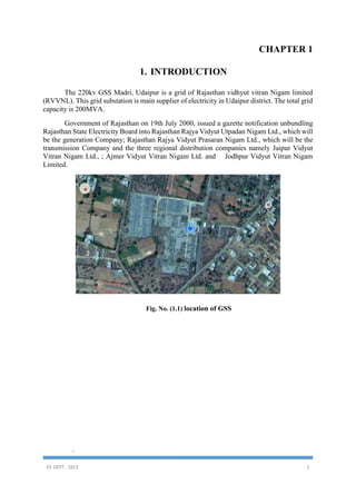
  • 1. EE DEPT. ,SSCE 1 CHAPTER 1 1. INTRODUCTION The 220kv GSS Madri, Udaipur is a grid of Rajasthan vidhyut vitran Nigam limited (RVVNL). This grid substation is main supplier of electricity in Udaipur district. The total grid capacity is 200MVA. Government of Rajasthan on 19th July 2000, issued a gazette notification unbundling Rajasthan State Electricity Board into Rajasthan Rajya Vidyut Utpadan Nigam Ltd., which will be the generation Company; Rajasthan Rajya Vidyut Prasaran Nigam Ltd., which will be the transmission Company and the three regional distribution companies namely Jaipur Vidyut Vitran Nigam Ltd., ; Ajmer Vidyut Vitran Nigam Ltd. and Jodhpur Vidyut Vitran Nigam Limited. Fig. No. (1.1) location of GSS .
  • 2. EE DEPT. ,SSCE 2 CHAPTER 2 2. INCOMMING AND OUTGOING LINES OF MADRI Table No. (2.1) Incoming and Outgoing INCOMING LINES 220KV OUTGOING LINES 220 KV INCOMING LINES 132KV OUTGOING LINES 132 KV OUTGOING LINES 33KV 1.DEBARI 1.BANSWARA 1.DEBARI 1.DEBARI 1.HIRAN MAGRI,SEC-4- 1 2.ZAWAR MINES 2.ZAWAR MINES 2.HIRAN MAGRI,SEC-4- 2 3.PRATAP NAGAR 3.PRATAPNAGA R 3.SAVINA-1 4.RSMM 4.SAVINA-2 5.RELIANCE CHEMOTEX 5.MIA-1 6.MIA-2 7.MATOON-1 8.MATOON-2
  • 3. EE DEPT. ,SSCE 3 CHAPTER 3 3. TRANSFORMERS 3.1 DEFINATION: Transformer is a static device by means of which electric power in one circuit is transformed into electric power of same frequency in another circuit. 3.2 Transformers used in GSS: Fig. No. (3.1) 220/132 KV, 100 MVA Transformer Fig. No. (3.2) 132/33 KV40/50 MVA Transformer
  • 4. EE DEPT. ,SSCE 4 Fig. No. (3.3) 132/33 KV20/25 MVA Transformer 3.3 Transformer parts: Core: In an electrical power transformer, there are primary, secondary and may be tertiary windings. The performance of a transformer mainly depends upon the flux linkages between these windings. For efficient flux linking between these windings, one low reluctance magnetic path common to all windings should be provided in the transformer. Windings: The windings consist of the current-carrying conductors wound around the sections of the core, and these must be properly insulated, supported and cooled to withstand operational and test conditions. Conservator tank: This is a cylindrical tank mounted on supporting structure on the roof the transformer main tank. The main function of conservator tank of transformer is to provide adequate space for expansion of oil inside the transformer. Fig. No. (3.4) Conservator tank
  • 5. EE DEPT. ,SSCE 5 Breather: Whenever electrical power transformer is loaded, the temperature of the transformer insulating oil increases, consequently the volume of the oil is increased. As the volume of the oil is increased, the air above the oil level in conservator will come out.. The natural air always consists of more or less moisture in it and this moisture can be mixed up with oil if it is allowed to enter into the transformer Fig. No. (3.5) Breather: Cooling equipment: The radiator of transformer accelerates the cooling rate of transformer. Thus, it plays a vital role in increasing loading capacity of an electrical transformer. This is basic function of radiator of an electrical power transformer. Fig. No. (3.6) Cooling equipment:
  • 6. EE DEPT. ,SSCE 6 CHAPTER 4 4. EARTHING The Earthing is of two principal types viz.  Neutral Earthing and  Equipment Body Earthing The neutral point of star-connected 3-phase winding of power transformers is connected to low resistance ground, such a connection is called 'Neutral grounding'. It gives advantages of stable neutral point, relatively simple earth fault relaying, discharge of over-voltages to earth due to lightning, control over earth fault current etc. SPECEFICATION OF TRANSFORMER: Fig. No. (4.1) 40/50 MVA Transformer Fig. No. (4.2) 100 MVA Transformer:
  • 7. EE DEPT. ,SSCE 7 CHAPTER 5 5. SWITCH YARD 5.1 Single line diagram (SLD): Fig. No. (5.1) Single line diagram
  • 8. EE DEPT. ,SSCE 8 5.2 YARD VIEW OF 220/132KV Fig. No. (5.2) YARD VIEW OF 220/132KV 5.3 EQUIPMENT ISOLATOR Fig. No. (5.3) Isolators 5.4 LIGHTENING ARRESTOR A surge arrester or lightning arrester is a device connected between line and earth, i.e., in parallel with the equipment to be protected at the substation. It limits the magnitude of lightning and switching over voltages at the substation and provides a low resistance path for the surge current to flow to the ground.
  • 9. EE DEPT. ,SSCE 9 Fig. No. (5.4) LIGHTENING ARRESTOR 5.6 CIRCUIT BREAKERS SF6 Circuit Breaker: SF6 is a heavy chemically inert nontoxic noninflammable gas. Its other properties, which make it ideal for circuit breaking, are:  At atmospheric pressure its dielectric strength is two to three times that of air. Because of excellent insulating properties of the gas, reduced electrical clearances are needed.  Its heat transferability at atmospheric pressure is 2 to 2.5 times that of air; therefore smaller conductor sizes needed. Fig. No. (5.5) SF6 Circuit Breaker
  • 10. EE DEPT. ,SSCE 10 Advantage of SF6 Circuit Breaker  Low gas velocity and pressure employed prevent current chopping; capacity currents are interrupted without restriking.  There is no exhaust of high pressure gas to atmosphere, and their operation is silent.  No carbon deposition takes place and as such, there is no insulation tracking.  The smaller size of conductor and clearances lead to small overall breaker size; and these have ample overload margin. VACUUM CIRCUIT BREAKER: In such breakers vacuum is used as the arc quenching medium. Since vacuum offer the highest insulating strength. It has for superior arc quenching properties than any other medium. Fig. No. (5.6) VACUUM CIRCUIT BREAKER 5.7 INSTRUMENT TRANSFORMER: CURRENT TRANSFORMER: These instrument transformers are connected in AC power circuits to feed the current coils of indicating and metering instruments (ammeter, wattmeter’s, and watt hour meters) and protective relays. Thus the CTs Borden the limits of measurements and maintain a watch over the currents flowing in the circuit and over the power loads. In high voltage installation CTs in addition to above, also isolate the indicating and metering instruments from high voltage. The current transformer basically consists of an iron core on which are wound a primary and one or two secondary windings
  • 11. EE DEPT. ,SSCE 11 Fig. No. (5.7) CURRENT TRANSFORMER: SPECIFICATION OF C.T.: Fig. No. (5.8) SPECIFICATION OF C.T POTENTIAL TRANSFORMER: The potential transformers are employed for voltage above 380 volts to feed the potential coils of indicating and metering instruments (volt meters, wattmeter’s, and watt hour meters) and relays. The primary winding of the potential transformers is connected to the main bus-bars of the switch gear installation and to the secondary windings; various indicating and metering instruments and relays are connected.
  • 12. EE DEPT. ,SSCE 12 Fig. No. (5.9) POTENTIAL TRANSFORMER 5.8 CAPACITOR VOLTAGE TRANSFORMER CVT:  Capacitor voltage transformer (C.V.T) can be effectively employed as potential source of measuring protection carrier communication and other function of an available for system voltage 33 KV to 400 KV  The performance of capacitance voltage transformer is inferior to that of electro magnet voltage transformer. Its performance affected by the Rating of CVT: Fig. No. (5.10) CVT
  • 13. EE DEPT. ,SSCE 13 Advantage of CVT:  Simple design and easy installation.  Frequency independence voltage distribution.  Provides isolation between the high voltage terminal and low voltage metering. 5.9 LINE TRAP/WAVE TRAP: Line trap also is known as Wave trap. What it does is trapping the high frequency communication signals sent on the line from the remote substation and diverting them to the telecom/teleportation panel in the substation control room (through coupling capacitor and LMU). Fig. No. (5.11) LINE TRAP/WAVE TRAP 6. PROTECTION OF TRANSFORMER: Buchholz Relay: The Buchholz relay is fitted in the pipe leading to the conservator. The gas gets collected in the upper portion of the relay, thereby the oil in the relay drops down. The float, floating in the oil in the relay tilts down with the lowering oil level. While doing so the mercury switch attached to the float is closed and the mercury switch closes the alarm circuit. The testing of gas gives clue regarding the type of insulation failure. When a serious short circuit occurs in the transformer, the pressure in the tank increases. The oil rushes towards the conservator. While doing so the it passes through the Buchholz relay. The baffles (plates) in the relay get pressed by the rushing oil. Thereby they close another switch which in turn closes the trip circuit of circuit-breaker.
  • 14. EE DEPT. ,SSCE 14 Fig. No. (5.12) Buchholz Relay Differential Protection The 'Differential protection' responds to the vector deference between two similar quantities. In protection of transformer, CT's are connected at each end of the transformer. The CT secondary are connected in star of delta and between the CT's of each end. The CT connections and CT ratios are such that currents fed into the pilot wires from both the ends are equal during normal conditions and for through fault
  • 15. EE DEPT. ,SSCE 15 CHAPTER 6 6. PLCC SECTION  PLCC is used for communication between stations. In power station, receiving stations and substations telephones are provided. These are connected to carrier current equipment and conversion can be carried out by means of ‘Power Line Carrier Communication. Each end of the line is provided with identical carrier current equipment consisting of transmitter, receiver, line-tuning unit, master oscillator, power amplifier, etc.  The carrier equipment is connected to the transmission line through 'coupling capacitor' which is of such a capacitance that it offers low reactance to carrier frequency but high reactance to power frequency. 'Line trap unit' is inserted between bus bar and connection of coupling capacitor to the line. It is a parallel tuned circuit comprising L and C. The unit prevents the high frequency signals from entering the neighboring line, and the carrier currents flow only in the protected line.  In a PLCC panel, there are three sections transmitter, receiver and speech sections. At the time of communication 'speech section' connects both transmitter and receiver to the telephone.
  • 16. EE DEPT. ,SSCE 16 CHAPTER 7 7. DC BATTERY SYSTEM Nests for (110v DC supply), one set is used for main supply and other is used for CB and control room operation. Fig. No. (7.1) DC BATTERY SYSTEM
  • 17. EE DEPT. ,SSCE 17 CHAPTER 8 8. LOAD FLOW DIAGRAM Fig. No. (8.1) LOAD FLOW DIAGRAM
  • 18. EE DEPT. ,SSCE 18 CHAPTER 9 9. REACTIVE POWER MANAGEMENT (power factor improvement) 9.1 CAPACITOR BANK: The capacitor gives following functions 1. Voltage rise 2. Energy storage 3. Power factor improvement  Three capacitor banks of 7.2 MVAR are used for power and voltage improvement. When the voltage level due to lagging load, the capacitor bank gets connected in EH line and capacitive reactance is more than inductive reactance of circuit and hence impedance of the line is reduced and the line voltage is maintained to desired level. Fig. No. (9.1) CAPACITOR BANK
  • 19. EE DEPT. ,SSCE 19 CHAPTER 10 10. PROTECTIVE RELAY SYSTEM 10.1 OVER CURRENT RELAY A digital overcurrent relay is type of protective relay which operates when the load current exceeds a pickup value. In a typical application the over current relay is connected to current transformer and calibrated to operate at or above a specific current level. When the relay operates, one or more contacts will operate and energize to trip (open) a circuit breaker. There are two basic forms of overcurrent relays: the instantaneous type and the time-delay type. The instantaneous overcurrent relay is designed to operate with no intentional time delay when the current exceed the relay setting. None less, the operating time of this type of relay can vary significantly. It may be as low as 0.016 seconds or as high as 0.1 seconds. The time-overcurrent relay has an operating characteristic such that its operating time varies inversely as the current flowing in the relay. It is the backup relay for the 220KV and 132KV system. It is also not present in the 33kv system. 10.2 EARTH FAULT PROTECTION RELAY Earth-fault relay is used to protect feeder against faults involving ground. It is connected commonly to the three phases. The value at which it gets tripped is kept very low so that a small fault can be easily detected. It is also the backup relay for the 220KV and 132KV system. It is also not present the 33kv system. 10.3 DISTANCE RELAY The working principle of distance relay or impedance relay is very simple. There is one voltage element potential transformer and a current element fed from current transformer of the system. The deflecting torque is produced by secondary current of CT and restoring torque is produced by voltage of potential transformer. In normal operating condition, restoring torque is more than deflecting torque. Hence relay will not operate
  • 20. EE DEPT. ,SSCE 20 CHAPTER 11 11. LOAD DISPATCH CENTER (LDC) 11.1 NATIONAL LOAD DISPATCH CENTER The main functions assigned to NLDC are:  Supervision over the Regional Load Dispatch Centers.  Scheduling and dispatch of electricity over the inter-regional links in- accordance with grid standards specified by the authority and grid code specified by central  Dissemination of information relating to operations of transmission system in accordance with directions or regulations issued by central government from time to time. 11.2 Regional Load Dispatch centers The main responsibilities of RLDCs are:  System parameters and security.  To ensure the integrated operation of the power system grid in the respective region.  System studies, planning and contingency analysis.  Daily scheduling and operational planning. Fig. No. (11.1) Regional Load Dispatch center
  • 21. EE DEPT. ,SSCE 21 CHAPTER 12 12. MAINTENANCE SCHEDULE: 12.1 FOR LIGHTING ARRESTOR: Table No. (12.1) FOR LIGHTING ARRESTOR ITEM NO FREQUENCY ITEM TO BE INSPECTED INSCEPTION ACTION REQUIRRED IF INSPECTION SHOWS UNSATISFACTORY CONDITON 1 2 3 4 5 1 Quarterly Surge counter Reading of Surge counter Normal counting rate is 0-5 counts a year. More than 10 counts is abnormal 2 Half yearly Surge Arrestor: cleaning 3 Half yearly LA Measurement of insulation Resistance The basic value more than 1000 M Ω with a 100 megger. 4 Half LA Measure Earth resistance and check earth connection. 5 yearly LA Check with current leakage meter A change of grading current of more than 500 12.2 FOR CURRENT TRANSFORMER: Table No. (12.2) FOR CURRENT TRANSFORMER ITEM NO FREQUENCY ITEM TO BE INSPECTED INSCEPTION ACTION REQUIRRED IF INSPECTION SHOWS UNSATISFACTORY CONDITON 1 2 3 4 5
  • 22. EE DEPT. ,SSCE 22 1 Daily Junction box Close/open If open than closed 2 Monthly Oil leakage checking If necessary add oil and plug leakage 3 Monthly Healthiness of Junction box Checking If not proper replace gasket 4 Monthly Oil level in CT Checking 5 Monthly CT Cleaning If necessary add oil and plug leakage 6 Half yearly CT Checking Compare with guaranteed value, if low take up with manufacturer 7 Half yearly Primary connection I.R. measurement DA ratio Compare with guaranteed value, if low take up with manufacturer 8 Half yearly Secondary conection Measurement of Tan delta & capacitance 9 Half yearly Continuity of CT Secondary wiring tightening 10 Half yearly Oil level gauge Tightening/ cleaning 11 Half yearly CT Secondary Resistnce Checking 12 Yearly CT Checking 13 Yearly CT Magnetization characteristics. 14 Yearly CT CT ratio test 15 Yearly OIL D.G.A
  • 23. EE DEPT. ,SSCE 23 12.3 FOR CVT (capacitor voltage transformer): Table No. (12.3) FOR CVT (capacitor voltage transformer) ITEM NO FREQUENCY ITEM TO BE INSPECTED INSCEPTION ACTION REQUIRRED IF INSPECTION SHOWS UNSATISFACTORY CONDITON 1 2 3 4 5 1 Weekly Base unit Oil level If necessary add oil and plug leakage 2 Weekly Top unitearthing of HF point Oil level If necessary add oil and plug leakage 3 Quarterly Dust deposits Oil level 4 Quarterly Oil leaks Visual checking If crack than replace 5 Quarterly Metring point Checking Plug the leakage 6 Quarterly Healthiness of gasskets CVT terminal voltage 7 Quarterly Tightness of terminal Checking 8 Half Yearly All connection Cleaning & tightening 9 Half Yearly Junction box Cleaning & tightening 10 Half Yearly Capacitor stacks Cleaning & tightening 11 Yearly CVT Tan delta measurement of CVT If temp. high. Replace CVT
  • 24. EE DEPT. ,SSCE 24 12 Yearly Oil Testing of EMU tank oil for BDV Compare with guaranteed values and take action as recommended 13 Yearly If BDV is low replace oil by new one 12.4 FOR SF6 CIRCUIT BREAKER: Table No. (12.4) FOR SF6 CIRCUIT BREAKER ITEM NO FREQUENCY ITEM TO BE INSPECTED INSCEPTION ACTION REQUIRRED IF INSPECTION SHOWS UNSATISFACTORY CONDITON 1 2 3 4 5 1 Daily Status of closing Closing spring shall be in charged condition If not charge the closing spring 2 Monthly SF6 gas is pressure if pressure gauge is provide Filling pressure If low check the SF6 gas leakage 3 Monthly Operation status Check the no of operations If there has been no operation of breaker in the past month 4 Quarterly Insulator Clean the isolators and check for any cracks Replaced the cracked insulator 5 Quarterly Clamp and connector Tightining all the clamp and connectors on the breaker Replace the damage clamps and nuts and bolts
  • 25. EE DEPT. ,SSCE 25 6 Quarterly Operation of breaker Check the mannual operation also electrical operation for local Check the control wring and mechanism 7 Quarterly Operation of breaker Lubricate all the moving parts Replaced the defactive parts 8 Quarterly SF6gas monitring circuits Tighten all the connection on the terminal blocks Replaced the damaged scrobes on the terminal blocks 9 Quarterly Operation counter Check that it is working Rectify defect on replaced 10 Quarterly Air compressor Check oil level and oil quality Adjust tension if required 11 Half Yearly For penumatic operated mechaism Mannualoperation of air compressor Adjust the pressure switch if required 12 Half Yearly For hydrallic operated mechaism Check the pressure marking time Adjust the pressure switch if required 13 Yearly Opening and closing timings Measurethe oppening and closing Time on the circuit breaker 14 Yearly Foundation bolts Check the tightness Tighten fondation bolts if required 15 Yearly Earthing Check the tightness of the earthing connection tightness of the earthing connection 16 Yearly Spring charging Check the tightness of wire connection Replaced the old out bushes
  • 26. EE DEPT. ,SSCE 26 CONCLUSION In conclusion to all the mentioned design aspects of the 220/132KV sub-station there are several other factors that are needed to be considered. This includes socio-economic factor of the surrounding locality, political developments, union of workers and contractors. Economic factors become chief aspect in any project which can take a prolonged period to complete. An assumption of price hike of all the materials to a higher precision is needed to be made in order to estimate the budget of this project. The mechanical and civil designs are also an essential part of any electrical substation design. Thus a lot of other engineering brains in those fields are also employed for the construction. Experts in the field of commerce and law are also employed to meet the various challenges that may rise up.