SlideShare una empresa de Scribd logo
1 de 22
Descargar para leer sin conexión
EE DEPT. SSCE 1
CHAPTER-1
1. INTRODUCTION
1.1 Mahi Hydel Power Station
The Mahi River is flowing in the southern part of Rajasthan near Banswara.The power
potential of this river has been exploited by constructing#following#two#Power#Houses:-
Table No.-1
Mahi Power House-I (2x25MW) Mahi Power House -II (2 x 45MW)
FRL 281.5M(923ft.) Up Stream reservoir level 220.5M(723.5ft)
Live storage capacity 65.45TMCuft Live storage capacity 1.53Million
cubic(54.4MCft)
Mahi Hydel Power Station is R.V.U.N.Ltd. Major Hydel generating station situated on river
Mahi near Banswara town, comprising of 2-phases of installed capacity 140MW.
Table No.-2
Stage Unit No. Capacity(MW)
Cost(Rs.
Core)
Synchronizing Date
I 1 25
68
22.1.1986
2 25 6.2.1986
II 1 45
119
15.2.1989
HYDEL POWER
STATIONS:-
2 45
17.9.1989
EE DEPT. SSCE 2
Fig. 1.1 Mahi Hydel Power Station
1.2Mahi Hydel Power Station (140 MW):
Two power houses are operating under this power station having total installed capacity
of 140 MW (2x25 & 2x45 MW). During last three years there had been appreciable decrease
in the power generation from this plant due to scanty rains in the region. The details of total
energy generated from this power station during last five years are as under:-
Table No.-3
Year Energy generated(MU)
1999-00 143.12
2000-01 36.37
2001-02 68.59
2002-03 22.06
2003-04 191.63
1.3 Proposed Anas Reservoir
Anas Dam
 Location – 4.0 KM U/S in river Anas to PH2 near village Gararia
 Length – 8 KM
 Type – Gated spill way
 T.B.L. – EL. 231.50 M
 F.R.L. – EL 228.50 M
 M.D.D.L. – EL 216.6 M
 Catchment Area – 1840 Sq. Miles
 Live Storage – 40 TMC
 Dead Storage – 9 TMC
Hydel Channel
 Length – 9 KM
 Discharge – 31.15 CUMECS
 Bed width – 7.0 M
EE DEPT. SSCE 3
 Side slope – 1:1
 Bed slope – 1 in 6000
 F.S.D. – 3.06 M

1.4 PLANT SPECIFICATION’S:- (2 X 45 MW)
• Capacity of machines : 2 x 45 MW.
• Type of turbine : FRANCIS[VERTICAL SHAFFT]
• Date of commissioning of Unit I : 22-1-1986.
• Date of commissioning of Unit II : 06-2-1986.
• Date of dedication of Nation : 13-2-1986.
• Type of generator : UMBRELLA Type.
• Capacity of generator : 27.778 MVA.
At 11 kV, 0.9pf, lag.
• Rated Speed : 250 rpm
• Capacity of power transformer : 11/132 kV,
31.5 MVA, 3-Ø.
1.5 ELEMENTARY DESCRIPTION OF “MAHI HYDRO POWER
STATION”
Definition:
A generating station which utilizes the potential energy of water at a high level for the
generation of electrical energy is known as a hydroelectric power station.
It contains the following of the elements:-
1. Dam:
A dam is barrier which stores water and creates water head. Dams are built of
concrete or stone masonry, earth or rock hill. The type of arrangement depends upon
the topography of the sight.
2. Penstock:
Penstock is open or closed conduits which carry water to the turbines. They are
generally made of reinforced concrete or steel. Concrete penstock is suitable for low or
medium as greater pressure causes rapid deterioration of concrete.
 Number – 2 nos.
 Length
o Unit 1 – 360.7 M
o Unit 2 – 361.2 M
 Diameter – 5 M
 Designed Discharge – 64.2 CUMECS
 Tunnel – 108 M
 EL at Intake – EL. 20 M
o EL at Power House – EL. 130 M
EE DEPT. SSCE 4
 Steel Plates – 16 MM to 25 MM
3. Reservoir:
It is constructed behind the dam to store water. From here the water takes to
turbine through the penstock. The generation depends upon the head of the water behind
dam. Generally the required head is about 281m
4. Water turbines:
Water turbines are used to convert the energy of falling water into electrical
energy. Here the water turbine used is FRANCIS type turbine; it is a reaction turbine
in which water enters the runner partly with pressure energy and partly with velocity
head.
5. Generating Units:
An alternator is connected with the shaft of turbine. The alternator used is of 3-
phase silent pole type, it is used for low speed. When shaft of water turbine starts to
rotate the generator also rotate and electricity is produced.
1.6 HYDROPOWER GENERATING STATIONS:-
Hydropower generating stations convert the energy of moving water into electrical
energy by means of a hydraulic turbine coupled to a synchronous generator. The power that
can be extracted from a waterfall depends upon its height and rate of flow. Therefore, the size
and physical location of a hydropower station depends on these two factors.
The available hydropower can be calculated by the following equation:
Where,
P = Available water power (kW)
q = Water rate of flow (m3/s)
h = Head of water (m)
9.8 = Coefficient used to take care of units.
The mechanical power output of the turbine is actually less than the value calculated by
the preceding equation. This is due to friction losses in the water conduits, turbine casing, and
the turbine itself. However, the efficiency of large hydraulic turbines is between 90 and 94
percent. The generator efficiency is even higher, ranging from 97 to 99 percent, depending on
the size of the generator.
Hydropower stations can be divided into three groups based on the head of water:
1. High-head development
2. Medium-head development
3. Low-head development
EE DEPT. SSCE 5
Fig.: 1.2 One-line diagram of electric-power system
High-head developments have heads in excess of 300 m, and high-speed turbines are
used. Such generating stations can be found in mountainous regions, and the amount of
impounded water is usually small. Medium-head developments have heads between 30 m and
300 m, and medium speed turbines are used. The generating station is typically fed by a large
reservoir of water retained by dikes and a dam. A large amount of water is usually.
EE DEPT. SSCE 6
CHAPTER-2
2. ELECTRICITY
Electrical#equipment#is dangerous if handled incorrectly; therefore, we
must observe all applicable safety pre-cautions when working with or around electrical
equipment. We will discuss basic concepts of electricity, electrical terms, electrical equipment,
and applicable safety precautions.
2.1 How is electricity made?
There are actually several ways of making electricity. Each technique involves the use
of a turbine to roll and renovate kinetic energy into electricity. Electricity is made when a
turbine moves a huge magnet around an extremely large wire. This movement provides to thrill
the wire. Electricity is then further pushed away from this generator by way of individual
transformers. Steam, combustion gases, and other water are usually used to turn turbines for
the generating electricity. Wind might as well be used. When steam is used, vestige fuels, such
as lubricate, gas, or coal, are frequently burned for the reason of generating steam from water.
The steam is then used to rotate the turbine and make electricity.
At times nuclear energy is also made use to generate steam to turn turbines. When
nuclear power is made used, uranium is rip apart, making heat energy. The heat energy is
functional to water, making steam for use in turning a turbine. Combustion gases might as well
be made use to make electricity. In usual such cases, a gas turbine are engaged in burning
natural gas or may be with low-sulfur oil. The fuel is mixed with condensed air and burned in
combustion chambers. In these chambers, high-pressure combustion gases shape up and are
then functional to the turbine, causing it to turn.
Sometimes water is made use when one wants to create electricity. In such a case, water
is made to drop on the blades of a turbine, rotating it. This needs an extremely large amount of
water, which is generally obtained from a pool or a lake. The body of water should be situated
higher than the turbine in order to turn its massive blades.
EE DEPT. SSCE 7
CHAPTER-3
3. How Hydropower Plants Work
Worldwide, hydropower plants produce about 24 percent of the world's electricity and supply
more than 1 billion people with power. The world's hydropower plants output a combined total
of 675,000 megawatts, the energy equivalent of 3.6 billion barrels of oil, according to the National
Renewable Energy Laboratory. There are more than 2,000 hydropower plants operating in the
United States, making hydropower the country's largest renewable energy source.
In this edition of HowStuffWorks, we'll take a look at how falling water creates energy and learn
about the hydrologic cycle that creates the water flow essential for hydropower. You will also
get a glimpse at one unique application of hydropower that may affect your daily life.
3.1 The Power of Water
When watching a river roll by, it's hard to imagine the force it's carrying. If you have ever been
white-water rafting, then you've felt a small part of the river's power. White-water rapids are
created as a river, carrying a large amount of water downhill, bottlenecks through a narrow
passageway. As the river is forced through this opening, its flow quickens. Floods are another
example of how much force a tremendous volume of water can have.
Hydropower plants harness water's energy and use simple mechanics to convert that energy into
electricity. Hydropower plants are actually based on a rather simple concept -- water flowing
through a dam turns a turbine, which turns a generator. :
Fig. 1.3 Most hydropower plants
EE DEPT. SSCE 8
Dam –
Most hydropower plants rely on a dam that holds back water, creating a large reservoir. Often,
this reservoir is used as a recreational lake, such as Lake Roosevelt at the Grand Coulee Dam in
Washington State.
Intake –
Gates on the dam open and gravity pulls the water through the penstock, a pipeline that leads to
the turbine. Water builds up pressure as it flows through this pipe.
Turbine –
The water strikes and turns the large blades of a turbine, which is attached to a generator above
it by way of a shaft. The most common type of turbine for hydropower plants is the Francis
Turbine, which looks like a big disc with curved blades. A turbine can weigh as much as 172
tons and turn at a rate of 90 revolutions per minute (rpm), according to the Foundation for Water
& Energy Education (FWEE).
Generators –
As the turbine blades turn, so do a series of magnets inside the generator. Giant magnets rotate
past copper coils, producing alternating current (AC) by moving electrons. (You'll learn more
about how the generator works later.)
Transformer –
The transformer inside the powerhouse takes the AC and converts it to higher-voltage current.
Power lines –
Out of every power plant come four wires: the three phases of power being produced
simultaneously plus a neutral or ground common to all three. (Read How Power Distribution Grids
Work to learn more about power line transmission.)
Outflow –
Used water is carried through pipelines, called tailraces, and re-enters the river downstream. The
water in the reservoir is considered stored energy. When the gates open, the water flowing
through the penstock becomes kinetic energy because it's in motion. The amount of electricity
that is generated is determined by several factors. Two of those factors are the volume of water
flow and the amount of hydraulic head. The head refers to the distance between the water surface
and the turbines. As the head and flow increase, so does the electricity generated. The head is
usually dependent upon the amount of water in the reservoir.
Pumped Storage
The majority of hydropower plants work in the manner described above. However, there's
EE DEPT. SSCE 9
another type of hydropower plant, called the pumped-storage plant. In a conventional
hydropower plant, the water from the reservoir flows through the plant, exits and is carried
down stream. A pumped-storage plant has two reservoirs:
Upper reservoir –
Like a conventional hydropower plant, a dam creates a reservoir. The water in this reservoir
flows through the hydropower plant to create electricity.
Lower reservoir - Water exiting the hydropower plant flows into a lower reservoir rather
than re-entering the river and flowing downstream.
Using a reversible turbine, the plant can pump water back to the upper reservoir. This is done in
off-peak hours. Essentially, the second reservoir refills the upper reservoir. By pumping water
back to the upper reservoir, the plant has more water to generate electricity during periods of
peak consumption.
3.2 Inside the Generator
The heart of the hydroelectric power plant is the generator. Most hydropower plants have several
of these generators.
Fig-1.4 The generators
The generator, as you might have guessed, generates the electricity. The basic process of
generating electricity in this manner is to rotate a series of magnets inside coils of wire.
EE DEPT. SSCE 10
=This process moves electrons, which produces electrical current.
TheHoover Dam has a total of 17 generators, each of which can generate up to 133 megawatts.
The total capacity of the Hoover Dam hydropower plant is 2,074 megawatts. Each generator is
made of certain basic parts:
Shaft
Excitor
Rotor
Stator
As the turbine turns, the excitor sends an electrical current to the rotor. The rotor is a series of
large electromegnets that spins inside a tightly-wound coil of copper wire, called the stator. The
magnetic field between the coil and the magnets creates an electric current.
In the Hoover Dam, a current of 16,500 volts moves from the generator to the transformer, where
the current ramps up to 230,000 volts before being transmitted.
EE DEPT. SSCE 11
CHAPTER-4
4. POWER TRANSFORMER
4.1 TRASNFORMER CONSTRUCTION:
There are two basic types of core assembly, core form and shell form. In the core form,
the windings are wrapped around the core, and the only return path for the flux is through the
center of the core. Since the core is located entirely inside the windings, it adds a little to the
structural integrity of the transformer’s frame. Core construction is desirable when
compactness is a major requirement. Figure Z-6 illustrates a number of core type configurations
for both single and multi-phase transformers.
Fig 1.5 -power transformer
This manu-aclontaions a generalized overview of the fundamentals of transformer
theory and operation. The transformer is one of the most reliable pieces of electrical distribution
equipment. It has no moving parts, requires minimal maintenance, and is capable of
withstanding overloads, surges, faults, and physical abuse that may damage or destroy other
items in the circuit. Often, the electrical event that burns up a motor, opens a circuit breaker,
or blows a fuse has a subtle effect on the transformer. Although the transformer may continue
to operate as before, repeat occurrences of such damaging electrical events, or lack of even
minimal maintenance can greatly accelerate the evenhml failure of the transformer.
The fact that a transformer continues to operate satisfactorily in spite of neglect and
abuse is a testament to its durability. However, this durability is no excuse for not providing
the proper care. Most of the effects of aging, faults, or abuse can be detected and corrected by
a comprehensive maintenance#and#testing#program.
EE DEPT. SSCE 12
4.2 COSERVATOR TANK:
[A]. Conservator or expansion type tanks use a separate tank to minimize the contact
between the transformer oil and the outside air (see figure). This conservator tank is usually
between 3 and 10 percent of the main tank’s size. The main tank is completely filed with oil,
and a small conservator tank is mounted above the main tank level. A sump system is used to
connect the two tanks, and only the conservator tank is allowed to be in contact with the outside
of transformer oil flow.
Fig. 1.6 COSERVATOR TANK
[B]. although this design minimizes contact with the oil in the main tank, the auxiliary
tank’s oil is subjected to a higher degree of contamination because it is making up for the
expansion and contraction of the main tank. Dangerous gases can form in the head space of the
auxiliary tank, and extreme caution should be exercised when working around this type of
transformer. The auxiliary tank’s oil must be changed periodically, along with a periodic
draining of the sump.
4.3 BUSHINGS:
The leads from the primary and secondary windings most be safely brought through the
tank to form a terminal connection point for the lie and load connections. The bushing insulator
is constructed to minimize the stresses at these points, and to provide a convenient connection
point
EE DEPT. SSCE 13
The bushing is designed to insulate a conductor from a barrier, such as a transformer lid, and
to safely conduct current from one side of the barrier to the other. Not only must the bushing
insulate the live lead from the tank surfaces, but it must also preserve the integrity of the tank’s
seal and not allow any water, air, or other outside contaminants to enter the tank.
Fig.1.7 - bushing
[A]. here are several types of bushing construction; they are usually distinguished by their
voltage ratings, although the classifications do overlap:
1. Solid (high alumina) ceramic-(up to w5kv).
2. Porcelain-oil filled (25 to 69Kv).
3. Porcelain-compound (epoxy) filled (25 to 69kV).
4. Porcelain--synthetic resin bonded paper-filled (34.5 to 115kV).
5. Porcelain-oil-impregnated paper-filled (above 69kV, but especially above 275kv).
[B]. For outdoor applications, the distance over the outside surface of the bushing is
increased by adding “petticoats” or “watersheds” to increase the creep age distance between
the line terminal and the tank. Contaminants will collect on the surfaces of the bushing and
form a conductive path. When this creep age distance is bridged by contaminants, the voltage
will flashover between the tank and the conductor. This is the reason why bushings must be
kept clean and free of contaminants.
[C]. Transformer bushings have traditionally been externally clad in porcelain because
of its excellent electrical and mechanical qualities. Porcelain insulators are generally oil-filled
beyond 35 kV to take advantage of the oil’s high dielectric strength. There are a number of
EE DEPT. SSCE 14
newer materials being used for bushings, including: fiberglass, epoxy, synthetic rubbers,
Teflon, and silica compounds. These materials have been in use for a relatively short tile, and
the manufacturer’s instructional literature should be consulted when working with these
bushings.
[D].Maintenance. Bushings require little maintenance other than an occasional
cleaning and checking the connections. Bushings should be inspected for cracks and chips, and
if found, should be touched-up with Glyptic paint or a similar type compound. Because,
bushings are often called on to support a potion of the line cable’s weight, it is important to
verify that any cracks have not influenced the mechanical strength of the bushing assembly.
[E]. Testing. Most bushings are provided with a voltage tap to allow for power factor
testing of the insulator. If they have no tap, then the power factor test must be performed using
the “hot collar” attachment of the test set. The insulation resistance-dielectric absorption test
can also be performed between the conductor and the ground connection.
4.4 LIGHTNING ARRESTERS:
Most transformer installations are subject to surge voltages originating from lightning
disturbances, switching operations, or circuit faults. Some of these transient conditions may
create abnormally high voltages from turn to turn, winding to winding, and from winding to
ground. The lightning arrester is designed and positioned so as to intercept and reduce the surge
voltage#before#it#reaches#the#electrical#system.
[A]. Construction. Lightning arresters are similar to big voltage bushings in both
appearance and construction. They use a porcelain exterior shell to provide insulation and
mechanical strength, and they use a dielectric filler material (oil, epoxy, or other materials) to
increase the dielectric strength (see Figure). Lightning arresters, however, are called on to
insulate normal operating voltages, and to conduct high level surges to ground. In its simplest
form, a lightning arrester is nothing more than a controlled gap across which normal operating
voltages cannot jump. When the voltages exceeds a predetermined level, it will be directed to
ground, away from the various components (including the transformer) of the circuit. There are
many variations to this construction. Some arresters use a series of capacitances to achieve a
controlled resistance value, while other types use a dielectric element to act as a valve material
that will throttle the surge current and divert it to ground.
EE DEPT. SSCE 15
[B]. Mechanism. Lightning arresters use petticoats to increase the creep age distances
across the outer sm. face to ground. Lightning arresters should be kept clean to prevent surface
contaminants from forming a flashover path. Lightning arresters have a metallic connection on
top and bottom. The connectors should be kept free of corrosion.
Fig-1.8 lightining arrestor
[C]. Testing. Lightning arresters are sometimes constructed by stacking a series of the
capacitive/dielectric elements to achieve the desired voltage rating. Power factor testing is
usually conducted across each of the individual elements, and, much like the power factor test
on the transformer’s windings, a ratio is computed between the real and apparent current values
to determine the power factor. A standard insulation resistance- dielectric absorption test can
also be performed on the lightning arrester between the line connection and ground.
4.5CURRENT TRANSFORMER:
(A) CONNECTION’s
(B) TOP VIEW OF C.T.
(C) POSITION ON TRANSFORMER (Location)
(D) C.T. OPEN FOR MENTINANCE
The primary winding of a current transformer
A current transformer is specified as being 600 A, 5 A class C200. Determine its
characteristics. This designation is based on ANSI Std. C57.13–1978. 600 A is the continuous
primary current rating, 5 A is the continuous secondary current rating, and the turns ratio is
600/5=120. C is the accuracy class, as defined in the standard. The number following the C,
which in this case is 200, is the voltage that the CT will deliver to the rated burden impedance
at 20 times rated current without exceeding 10 percent error. Therefore, the rated burden
impedance is This CT is able to deliver up to 100 A secondary current to load burdens of up to
EE DEPT. SSCE 16
20 with less than 10 percent error. Note that the primary source of error is the saturation of the
CT iron core and that 200 V will be approximately the knee voltage on the CT saturation curve.
This implies that higher burden impedances can be driven by CT’s which will not experience
fault duties of 20 times rated current, for example.
A typical wave CT connection is shown in Fig. The neutral points of the CT’s are tied
together, forming a residual point. Four wires, the three-phase leads and the residual, are taken
to the relay and instrument location. The three-phase currents are fed to protective relays or
meters, which are connected in series. After these, the phases are connected to form and tied
back to the residual.
EE DEPT. SSCE 17
CHAPTER-5
5. GENERATORS
5.1 AC GENERATORS:-
AC generators are also called alternators. In an ac generator, the field rotates, and the
armature is stationary. To avoid confusion, the rotating members of dc generators are called
armatures; in ac generators, they are called rotors. The general construction of ac generators is
somewhat simpler than that of dc generators. An ac generator, like a dc generator, has magnetic
fields and an armature. In a small ac generator the armature revolves, the field is stationary, and
no commentator is required. In a large ac generator, the field revolves and the armature is
wound on the stationary member or stator. The principal advantages of the revolving-field
generators over the revolving-armature generators are two essential parts of a dc generator: are
as follows: The yoke and field windings, which are the load current from the stator is stationary,
and connected directly to the external circuit the armature, which rotates without
using a commentator.
5.2 GENERATOR:-
Technical parameters of generator
 Type of product – 5 V 596/152-24
 Speed – 250 rpm
 Runaway speed – 475 rpm
 Power factor – 0.9 lag
 Rated voltage – 11 KV
 Rated output – 45 MW
 Rated Output at Rated Voltage Zero Leading p.f. (Sync. Con. Operation) – 32
MVAR
 Rated frequency – 50 Hz
 Flying wheel effect of the rotating parts GD2
– Tonne M2 2100
 Armature winding resistance per phase at 75 o
C – 0.0086 Ω
 Resistance of winding per phase at 15 o
C – 0.00693 Ω
 Resistance of field winding at 75 o
C – 0.164 Ω
 Resistance of rotor field winding at 15 o
C – 0.121 Ω
5.3 STATOR:
The stator core and winding are housed in a fabricated steel frame made in four sections.
The stator core is built of vanished segmental silicon steel laminations held in the frame by
dovetailed key bars, welded to the frame. The core is divided into the packets by narrow radial
steel spears, thus forming ventilating ducts leading from the stator core to the outside periphery.
The core is clamped between the bottom frame plate and segmental flanges on the top by means
of through bolts.
 Stator Core inside diameter – 5250 mm
 Stator Core outside diameter – 5960 mm
 Gross Length of core – 1520 mm
 Net Length of core – 1162 mm
EE DEPT. SSCE 18
 Total weight of Iron – 50,000 Kgs
 Total no. of slots – 306
Calculated Capacitance of Stator Winding per phase – 0.36 MF
The stator winding is of the double layer three turned diamond pulled coil type,
assembled in open slots. Each coil is made of a number of insulated copper strands, with a
semi-rebel transposition in the end of Epoxy Movolac glass Mica paper tapes and flexible Mica
flakes taps in the end winding. All the coils are identical and interchangeable. Temperature
sensors of resistance type are inserted between coil sides in all three phases to provide a
continuous indication of coil temperature.
5.4 ROTOR:
The rotor is of the friction held type and is built up of thin sheet steel laminations rigidly
clamped between steel and plates by a large number of through bolts. The clamping force in
the rim is such that the fractional forces between the laminations prevent them from slipping
relative to one another at any speed up to and including runway.
The spider which supports the rim is of fabricated steel construction with dished arms from a
central hub. The lower plane is machined to fit on top of the generator shaft. The driving torque
is transmitted from the shaft to the spider by radial keys. This method of construction permits
the lifting of rotor independent of the shaft. The weight of the rim and poles is supported on
the heavy steel bars welded on the outer end of the spider arms.
 No. of poles – 24
 Weight of Copper in field winding in pole – 360 Kgs
 Width and Height of the pole body – 345 Х 212 mm
 Total weight of rotor – 15,5,000 Kgs
 No. of brushes per collector ring – 16
 Types of Collector Ring Brush - Electro Graphite Carlooun Brush

The field poles are built up of sheet steel punching clamped between steel and plates
and secured to the rim by two T-head projections on each punching and end plate. These
projections engage with corresponding slots in the rotor rim. Two pairs of tapered keys driven
along the slots pull the poles down on the rim.
Each pole carries a field coil made from straight lengths of copper straps, dovetailed and brazed
at the ends. At intervals down each coil, the copper is increased in width to from fins for
improved cooling. The inter turn insulation is of epoxy resign bonded asbestos paper and the
insulation between the coil and pole body is epoxy glass fabric bored.
In addition, each pole is equipped with six damper bars of circular cross section made of high
conductivity copper embedded in semi-closed slots in the pole face, which are brazed at each
end into copper punching clamped between pole and end plates. Axial flow aero-fill type fans
are mounted at each end of the rotor. A polished steel segmental brake track is bolted to the
bottom of the spider hub.
5.5 AIR COOLER:
Each of the twin shades of air coolers consists of a nest of admiralty Brass cubes wound
with copper wire covered in a mild steel frame. The tube ends are roller expanded into Brass
plates on which are mounted the inlet and return end water boxes fabricated from mild steel.
The thickness of water box includes generous corrosion allowance and these are internally
subdivided to provide for multiple water passes for requisite flow pattern. The inlet water box
is filled with vent valve and with drain valve. The differential thermal expansion between tubes
EE DEPT. SSCE 19
and frame is absorbed by the action of neoprene packing between the frame and the tube plate.
The coolers are provided with support foot plates at the bottom for baling down to the concrete
foundations. A drip tray is provided below the cooler for collecting any condensate.
5.6 OIL COOLERS:
Each of the four plug-in-type oil coolers consists of a bank of 'U' shapes admiralty Brass
tube with Copper wire carried in a Steel frame with inlet end terminating in a rolled Brass tube
plate and the other 'U' end supported in a tube support fixed frame. The tube rollers expanded
into the tube plate. The water box which is of mild steel fabrication is belted to the tube plate
and amply proportional to reduce turbulence and pressure drop. The differential thermal
expansion between tube and frame is absorbed by the 'U' shaped tubes.
5.7 GENERATOR TYPES AND DRIVES:-
A large amount of electricity is required to power machinery that supplies to Drives.
Fig.1.9 -generator
5.8 PERMANENT MAGNET GENERATOR (P M G):
The PMG provides a 3-Ø low voltage supply to the turbine governed at a frequency directly
related to the speed of the set. Provision has been made for synchronizing its voltage to that of
main generator during its excitation, if required for turbine governor operation.
EE DEPT. SSCE 20
5.9 PERMANENT MAGNET GENERATOR
 Type – PMG 104/0.24
 Capacity – 250 VA
 Voltage – 110 V
 Current – 1.3 Amp
 Speed – 250 rpm
 Frequency – 50 Hz
5.10 COLLECTOR RINGS AND BRUSH GEARS:
The collector rings are attached to and are insulated from the fabricated steel shaft
mounted on the spider. The leads from the collector to the field run along the shaft and joined
at suitable points to facilitate dismantling of the rotor.
A DC generator is a rotating machine that changes mechanical energy to electrical energy.
The power output depends on the size and design of the dc generator. A typical
dc generator is shown in figure.
Fig.-1.10 D.C Excitor
5.11 D.C. EXCITOR: -
» Rated output 255 kW.
» Rated voltage 178 V.
» Ceiling voltage 279 V-max.
» Rated speed 250 rpm.
» Exciter response ratio 1.5 p.v.
» No. of poles 8
» Max. Temperature rise at rated output at armature winding, armature core field
winding
And Core, =70°c.
EE DEPT. SSCE 21
» Armature circuit resistance= 0.0179 at 75°c
» No. of Brushes -8*5=40
» Exciter field current at rated output= 40.8amp. (MCR=55.7 amp.).
EE DEPT. SSCE 22
CHAPTER-6
6. CONCLUSION
A student gets theoretical knowledge from classroom and gets practical knowledge
from industrial training. When these two aspects of theoretical knowledge and practical
experience together then a student is full equipped to secure his best.
In conducting the project study in an industry, students get exposed and have knowledge of
real situation in the work field and gains experience from them. The object of the summer
training cum project is to provide an opportunity to experience the practical aspect of
Technology in any organization. It provides a chance to get the feel of the organization and its
function.
I have privilege taking my practical training at " MAHI HYDRO POWER HOUSE - I
" where power generation takes place in bulk. The fact that Hydro energy is the major source
of power generation itself shows the importance of Hydro power generation in India
In Hydro power plants, the potential energy of water is utilized by the turbine to rotate
coil at high torque. The torque so produced is used in driving the coil coupled to generators
and thus in generating ELECTRICAL ENERGY.

Más contenido relacionado

La actualidad más candente

La actualidad más candente (20)

Pumped storage hydro power plant
Pumped storage hydro power plantPumped storage hydro power plant
Pumped storage hydro power plant
 
RAPS
RAPSRAPS
RAPS
 
Micro hydro power plant
Micro hydro power plantMicro hydro power plant
Micro hydro power plant
 
Hydro Electric Power Plant | Hydel Power Plant
Hydro Electric Power Plant | Hydel Power PlantHydro Electric Power Plant | Hydel Power Plant
Hydro Electric Power Plant | Hydel Power Plant
 
Hydro power plant
Hydro power plantHydro power plant
Hydro power plant
 
Hydro power plant
Hydro power plantHydro power plant
Hydro power plant
 
Hydropower projects in Jammu and Kashmir
Hydropower projects in Jammu and KashmirHydropower projects in Jammu and Kashmir
Hydropower projects in Jammu and Kashmir
 
Hydro power plant
Hydro power plantHydro power plant
Hydro power plant
 
HYDRO POWER STATION
HYDRO POWER STATIONHYDRO POWER STATION
HYDRO POWER STATION
 
Hydro electric power plant
Hydro electric power plantHydro electric power plant
Hydro electric power plant
 
NPCIL RAWATBHATA PPT
NPCIL RAWATBHATA PPTNPCIL RAWATBHATA PPT
NPCIL RAWATBHATA PPT
 
Hydro power plant
Hydro power plantHydro power plant
Hydro power plant
 
Ppt for power plant
Ppt for power plantPpt for power plant
Ppt for power plant
 
Rps plant
Rps plantRps plant
Rps plant
 
RAPS
RAPSRAPS
RAPS
 
Kotmale power station
Kotmale power stationKotmale power station
Kotmale power station
 
MAHI HYDEL POWER PLANT REPORT
MAHI HYDEL POWER PLANT REPORTMAHI HYDEL POWER PLANT REPORT
MAHI HYDEL POWER PLANT REPORT
 
Generation of Electrical Power - Power Plants and Transmission Systems.
Generation of Electrical Power - Power Plants and Transmission Systems.Generation of Electrical Power - Power Plants and Transmission Systems.
Generation of Electrical Power - Power Plants and Transmission Systems.
 
NPCIL-Summer Training Report-2015
NPCIL-Summer Training Report-2015NPCIL-Summer Training Report-2015
NPCIL-Summer Training Report-2015
 
summer training report on nuclear power corporation of india
summer training  report on nuclear power corporation of indiasummer training  report on nuclear power corporation of india
summer training report on nuclear power corporation of india
 

Similar a RRVUN hydro power plant

Hydro Electric Power Plant
Hydro Electric Power Plant Hydro Electric Power Plant
Hydro Electric Power Plant ANKIT KUMAR
 
Hydro power plant presentation project by pratik diyora 100420106008
Hydro power plant presentation project by pratik diyora 100420106008Hydro power plant presentation project by pratik diyora 100420106008
Hydro power plant presentation project by pratik diyora 100420106008Pratik Diyora
 
Hydro Power Plant
Hydro Power PlantHydro Power Plant
Hydro Power Planttavinav
 
l1intro to hydroelectric power
  l1intro to hydroelectric power  l1intro to hydroelectric power
l1intro to hydroelectric powerGhassan Hadi
 
Hydroelectric power plant
Hydroelectric power plantHydroelectric power plant
Hydroelectric power plantMuddassar Awan
 
Hydroelectric power plant
Hydroelectric power plantHydroelectric power plant
Hydroelectric power plantMuddassar Awan
 
T&S_ppt final for Hydro Electric Power Plant Presentation
T&S_ppt final for Hydro Electric Power Plant PresentationT&S_ppt final for Hydro Electric Power Plant Presentation
T&S_ppt final for Hydro Electric Power Plant PresentationVishalChavan937224
 
PRINCIPLES OF HYDROPOWER ENGINEERING
PRINCIPLES OF HYDROPOWERENGINEERINGPRINCIPLES OF HYDROPOWERENGINEERING
PRINCIPLES OF HYDROPOWER ENGINEERINGArkan Hamza Gardi
 
introduction to hydroelectric power
 introduction  to hydroelectric power introduction  to hydroelectric power
introduction to hydroelectric powerGhassan Hadi
 
Report on-water-turbines
Report on-water-turbinesReport on-water-turbines
Report on-water-turbinesKANAIYABHATT
 
Lecture 18-DE.pdf
Lecture  18-DE.pdfLecture  18-DE.pdf
Lecture 18-DE.pdfshaymaa17
 

Similar a RRVUN hydro power plant (20)

Hydro Electric Power Plant
Hydro Electric Power Plant Hydro Electric Power Plant
Hydro Electric Power Plant
 
Hydro power plant presentation project by pratik diyora 100420106008
Hydro power plant presentation project by pratik diyora 100420106008Hydro power plant presentation project by pratik diyora 100420106008
Hydro power plant presentation project by pratik diyora 100420106008
 
Hydro power plant
Hydro power plantHydro power plant
Hydro power plant
 
Tidal energy
Tidal energyTidal energy
Tidal energy
 
Hydro Power Plant
Hydro Power PlantHydro Power Plant
Hydro Power Plant
 
hydro power plant
hydro power planthydro power plant
hydro power plant
 
l1intro to hydroelectric power
  l1intro to hydroelectric power  l1intro to hydroelectric power
l1intro to hydroelectric power
 
Hydroelectric power plant
Hydroelectric power plantHydroelectric power plant
Hydroelectric power plant
 
Hydroelectric power plant
Hydroelectric power plantHydroelectric power plant
Hydroelectric power plant
 
Hydroelectric powerplant
Hydroelectric powerplant Hydroelectric powerplant
Hydroelectric powerplant
 
T&S_ppt final for Hydro Electric Power Plant Presentation
T&S_ppt final for Hydro Electric Power Plant PresentationT&S_ppt final for Hydro Electric Power Plant Presentation
T&S_ppt final for Hydro Electric Power Plant Presentation
 
Hydro Power Plants
Hydro Power PlantsHydro Power Plants
Hydro Power Plants
 
PRINCIPLES OF HYDROPOWER ENGINEERING
PRINCIPLES OF HYDROPOWERENGINEERINGPRINCIPLES OF HYDROPOWERENGINEERING
PRINCIPLES OF HYDROPOWER ENGINEERING
 
introduction to hydroelectric power
 introduction  to hydroelectric power introduction  to hydroelectric power
introduction to hydroelectric power
 
science project.pptx
science project.pptxscience project.pptx
science project.pptx
 
Hydro power
Hydro powerHydro power
Hydro power
 
Report on-water-turbines
Report on-water-turbinesReport on-water-turbines
Report on-water-turbines
 
Hydro electric power plant
Hydro electric power plantHydro electric power plant
Hydro electric power plant
 
Lecture 18-DE.pdf
Lecture  18-DE.pdfLecture  18-DE.pdf
Lecture 18-DE.pdf
 
Hydropower
HydropowerHydropower
Hydropower
 

Más de ravi kant

MEMS technology technical seminar report
MEMS technology technical seminar report MEMS technology technical seminar report
MEMS technology technical seminar report ravi kant
 
smart meter technical seminar report
smart meter technical seminar reportsmart meter technical seminar report
smart meter technical seminar reportravi kant
 
Smart energy metering system
Smart energy metering systemSmart energy metering system
Smart energy metering systemravi kant
 
indian railway training report
indian railway training reportindian railway training report
indian railway training reportravi kant
 
BSNL training report
BSNL training reportBSNL training report
BSNL training reportravi kant
 
kota thermal power plant
kota thermal power plantkota thermal power plant
kota thermal power plantravi kant
 
Vedanta Hindustan zinc training
Vedanta Hindustan zinc trainingVedanta Hindustan zinc training
Vedanta Hindustan zinc trainingravi kant
 
Thermal power plant
Thermal power plantThermal power plant
Thermal power plantravi kant
 
Ntpc kahalgaon training report
Ntpc kahalgaon training reportNtpc kahalgaon training report
Ntpc kahalgaon training reportravi kant
 
Circuit breaker presentation
Circuit breaker presentationCircuit breaker presentation
Circuit breaker presentationravi kant
 
Aditya birla cement training report
Aditya birla cement training reportAditya birla cement training report
Aditya birla cement training reportravi kant
 
Hindustan zinc report
Hindustan zinc reportHindustan zinc report
Hindustan zinc reportravi kant
 
Hindustan zinc report
Hindustan zinc reportHindustan zinc report
Hindustan zinc reportravi kant
 
grid sub-station training Report
grid sub-station training Report grid sub-station training Report
grid sub-station training Report ravi kant
 

Más de ravi kant (15)

MEMS technology technical seminar report
MEMS technology technical seminar report MEMS technology technical seminar report
MEMS technology technical seminar report
 
smart meter technical seminar report
smart meter technical seminar reportsmart meter technical seminar report
smart meter technical seminar report
 
Smart energy metering system
Smart energy metering systemSmart energy metering system
Smart energy metering system
 
indian railway training report
indian railway training reportindian railway training report
indian railway training report
 
BSNL training report
BSNL training reportBSNL training report
BSNL training report
 
kota thermal power plant
kota thermal power plantkota thermal power plant
kota thermal power plant
 
Vedanta Hindustan zinc training
Vedanta Hindustan zinc trainingVedanta Hindustan zinc training
Vedanta Hindustan zinc training
 
Thermal power plant
Thermal power plantThermal power plant
Thermal power plant
 
Ntpc kahalgaon training report
Ntpc kahalgaon training reportNtpc kahalgaon training report
Ntpc kahalgaon training report
 
Circuit breaker presentation
Circuit breaker presentationCircuit breaker presentation
Circuit breaker presentation
 
Aditya birla cement training report
Aditya birla cement training reportAditya birla cement training report
Aditya birla cement training report
 
Hindustan zinc report
Hindustan zinc reportHindustan zinc report
Hindustan zinc report
 
Hindustan zinc report
Hindustan zinc reportHindustan zinc report
Hindustan zinc report
 
GSS ppt
GSS pptGSS ppt
GSS ppt
 
grid sub-station training Report
grid sub-station training Report grid sub-station training Report
grid sub-station training Report
 

Último

UNIT - IV - Air Compressors and its Performance
UNIT - IV - Air Compressors and its PerformanceUNIT - IV - Air Compressors and its Performance
UNIT - IV - Air Compressors and its Performancesivaprakash250
 
Booking open Available Pune Call Girls Pargaon 6297143586 Call Hot Indian Gi...
Booking open Available Pune Call Girls Pargaon  6297143586 Call Hot Indian Gi...Booking open Available Pune Call Girls Pargaon  6297143586 Call Hot Indian Gi...
Booking open Available Pune Call Girls Pargaon 6297143586 Call Hot Indian Gi...Call Girls in Nagpur High Profile
 
Online banking management system project.pdf
Online banking management system project.pdfOnline banking management system project.pdf
Online banking management system project.pdfKamal Acharya
 
Unit 2- Effective stress & Permeability.pdf
Unit 2- Effective stress & Permeability.pdfUnit 2- Effective stress & Permeability.pdf
Unit 2- Effective stress & Permeability.pdfRagavanV2
 
Unleashing the Power of the SORA AI lastest leap
Unleashing the Power of the SORA AI lastest leapUnleashing the Power of the SORA AI lastest leap
Unleashing the Power of the SORA AI lastest leapRishantSharmaFr
 
XXXXXXXXXXXXXXXXXXXXXXXXXXXXXXXXXXXXXXXXXXXXXXXXXXXX
XXXXXXXXXXXXXXXXXXXXXXXXXXXXXXXXXXXXXXXXXXXXXXXXXXXXXXXXXXXXXXXXXXXXXXXXXXXXXXXXXXXXXXXXXXXXXXXXXXXXXXXX
XXXXXXXXXXXXXXXXXXXXXXXXXXXXXXXXXXXXXXXXXXXXXXXXXXXXssuser89054b
 
FULL ENJOY Call Girls In Mahipalpur Delhi Contact Us 8377877756
FULL ENJOY Call Girls In Mahipalpur Delhi Contact Us 8377877756FULL ENJOY Call Girls In Mahipalpur Delhi Contact Us 8377877756
FULL ENJOY Call Girls In Mahipalpur Delhi Contact Us 8377877756dollysharma2066
 
Thermal Engineering -unit - III & IV.ppt
Thermal Engineering -unit - III & IV.pptThermal Engineering -unit - III & IV.ppt
Thermal Engineering -unit - III & IV.pptDineshKumar4165
 
Block diagram reduction techniques in control systems.ppt
Block diagram reduction techniques in control systems.pptBlock diagram reduction techniques in control systems.ppt
Block diagram reduction techniques in control systems.pptNANDHAKUMARA10
 
Thermal Engineering Unit - I & II . ppt
Thermal Engineering  Unit - I & II . pptThermal Engineering  Unit - I & II . ppt
Thermal Engineering Unit - I & II . pptDineshKumar4165
 
Double rodded leveling 1 pdf activity 01
Double rodded leveling 1 pdf activity 01Double rodded leveling 1 pdf activity 01
Double rodded leveling 1 pdf activity 01KreezheaRecto
 
KubeKraft presentation @CloudNativeHooghly
KubeKraft presentation @CloudNativeHooghlyKubeKraft presentation @CloudNativeHooghly
KubeKraft presentation @CloudNativeHooghlysanyuktamishra911
 
AKTU Computer Networks notes --- Unit 3.pdf
AKTU Computer Networks notes ---  Unit 3.pdfAKTU Computer Networks notes ---  Unit 3.pdf
AKTU Computer Networks notes --- Unit 3.pdfankushspencer015
 
Intro To Electric Vehicles PDF Notes.pdf
Intro To Electric Vehicles PDF Notes.pdfIntro To Electric Vehicles PDF Notes.pdf
Intro To Electric Vehicles PDF Notes.pdfrs7054576148
 
Work-Permit-Receiver-in-Saudi-Aramco.pptx
Work-Permit-Receiver-in-Saudi-Aramco.pptxWork-Permit-Receiver-in-Saudi-Aramco.pptx
Work-Permit-Receiver-in-Saudi-Aramco.pptxJuliansyahHarahap1
 
University management System project report..pdf
University management System project report..pdfUniversity management System project report..pdf
University management System project report..pdfKamal Acharya
 
notes on Evolution Of Analytic Scalability.ppt
notes on Evolution Of Analytic Scalability.pptnotes on Evolution Of Analytic Scalability.ppt
notes on Evolution Of Analytic Scalability.pptMsecMca
 

Último (20)

UNIT - IV - Air Compressors and its Performance
UNIT - IV - Air Compressors and its PerformanceUNIT - IV - Air Compressors and its Performance
UNIT - IV - Air Compressors and its Performance
 
FEA Based Level 3 Assessment of Deformed Tanks with Fluid Induced Loads
FEA Based Level 3 Assessment of Deformed Tanks with Fluid Induced LoadsFEA Based Level 3 Assessment of Deformed Tanks with Fluid Induced Loads
FEA Based Level 3 Assessment of Deformed Tanks with Fluid Induced Loads
 
Booking open Available Pune Call Girls Pargaon 6297143586 Call Hot Indian Gi...
Booking open Available Pune Call Girls Pargaon  6297143586 Call Hot Indian Gi...Booking open Available Pune Call Girls Pargaon  6297143586 Call Hot Indian Gi...
Booking open Available Pune Call Girls Pargaon 6297143586 Call Hot Indian Gi...
 
Online banking management system project.pdf
Online banking management system project.pdfOnline banking management system project.pdf
Online banking management system project.pdf
 
Unit 2- Effective stress & Permeability.pdf
Unit 2- Effective stress & Permeability.pdfUnit 2- Effective stress & Permeability.pdf
Unit 2- Effective stress & Permeability.pdf
 
Unleashing the Power of the SORA AI lastest leap
Unleashing the Power of the SORA AI lastest leapUnleashing the Power of the SORA AI lastest leap
Unleashing the Power of the SORA AI lastest leap
 
XXXXXXXXXXXXXXXXXXXXXXXXXXXXXXXXXXXXXXXXXXXXXXXXXXXX
XXXXXXXXXXXXXXXXXXXXXXXXXXXXXXXXXXXXXXXXXXXXXXXXXXXXXXXXXXXXXXXXXXXXXXXXXXXXXXXXXXXXXXXXXXXXXXXXXXXXXXXX
XXXXXXXXXXXXXXXXXXXXXXXXXXXXXXXXXXXXXXXXXXXXXXXXXXXX
 
Cara Menggugurkan Sperma Yang Masuk Rahim Biyar Tidak Hamil
Cara Menggugurkan Sperma Yang Masuk Rahim Biyar Tidak HamilCara Menggugurkan Sperma Yang Masuk Rahim Biyar Tidak Hamil
Cara Menggugurkan Sperma Yang Masuk Rahim Biyar Tidak Hamil
 
FULL ENJOY Call Girls In Mahipalpur Delhi Contact Us 8377877756
FULL ENJOY Call Girls In Mahipalpur Delhi Contact Us 8377877756FULL ENJOY Call Girls In Mahipalpur Delhi Contact Us 8377877756
FULL ENJOY Call Girls In Mahipalpur Delhi Contact Us 8377877756
 
Thermal Engineering -unit - III & IV.ppt
Thermal Engineering -unit - III & IV.pptThermal Engineering -unit - III & IV.ppt
Thermal Engineering -unit - III & IV.ppt
 
Block diagram reduction techniques in control systems.ppt
Block diagram reduction techniques in control systems.pptBlock diagram reduction techniques in control systems.ppt
Block diagram reduction techniques in control systems.ppt
 
Thermal Engineering Unit - I & II . ppt
Thermal Engineering  Unit - I & II . pptThermal Engineering  Unit - I & II . ppt
Thermal Engineering Unit - I & II . ppt
 
Double rodded leveling 1 pdf activity 01
Double rodded leveling 1 pdf activity 01Double rodded leveling 1 pdf activity 01
Double rodded leveling 1 pdf activity 01
 
KubeKraft presentation @CloudNativeHooghly
KubeKraft presentation @CloudNativeHooghlyKubeKraft presentation @CloudNativeHooghly
KubeKraft presentation @CloudNativeHooghly
 
AKTU Computer Networks notes --- Unit 3.pdf
AKTU Computer Networks notes ---  Unit 3.pdfAKTU Computer Networks notes ---  Unit 3.pdf
AKTU Computer Networks notes --- Unit 3.pdf
 
Intro To Electric Vehicles PDF Notes.pdf
Intro To Electric Vehicles PDF Notes.pdfIntro To Electric Vehicles PDF Notes.pdf
Intro To Electric Vehicles PDF Notes.pdf
 
(INDIRA) Call Girl Bhosari Call Now 8617697112 Bhosari Escorts 24x7
(INDIRA) Call Girl Bhosari Call Now 8617697112 Bhosari Escorts 24x7(INDIRA) Call Girl Bhosari Call Now 8617697112 Bhosari Escorts 24x7
(INDIRA) Call Girl Bhosari Call Now 8617697112 Bhosari Escorts 24x7
 
Work-Permit-Receiver-in-Saudi-Aramco.pptx
Work-Permit-Receiver-in-Saudi-Aramco.pptxWork-Permit-Receiver-in-Saudi-Aramco.pptx
Work-Permit-Receiver-in-Saudi-Aramco.pptx
 
University management System project report..pdf
University management System project report..pdfUniversity management System project report..pdf
University management System project report..pdf
 
notes on Evolution Of Analytic Scalability.ppt
notes on Evolution Of Analytic Scalability.pptnotes on Evolution Of Analytic Scalability.ppt
notes on Evolution Of Analytic Scalability.ppt
 

RRVUN hydro power plant

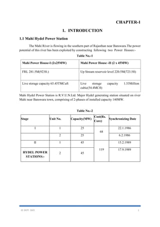
  • 1. EE DEPT. SSCE 1 CHAPTER-1 1. INTRODUCTION 1.1 Mahi Hydel Power Station The Mahi River is flowing in the southern part of Rajasthan near Banswara.The power potential of this river has been exploited by constructing#following#two#Power#Houses:- Table No.-1 Mahi Power House-I (2x25MW) Mahi Power House -II (2 x 45MW) FRL 281.5M(923ft.) Up Stream reservoir level 220.5M(723.5ft) Live storage capacity 65.45TMCuft Live storage capacity 1.53Million cubic(54.4MCft) Mahi Hydel Power Station is R.V.U.N.Ltd. Major Hydel generating station situated on river Mahi near Banswara town, comprising of 2-phases of installed capacity 140MW. Table No.-2 Stage Unit No. Capacity(MW) Cost(Rs. Core) Synchronizing Date I 1 25 68 22.1.1986 2 25 6.2.1986 II 1 45 119 15.2.1989 HYDEL POWER STATIONS:- 2 45 17.9.1989
  • 2. EE DEPT. SSCE 2 Fig. 1.1 Mahi Hydel Power Station 1.2Mahi Hydel Power Station (140 MW): Two power houses are operating under this power station having total installed capacity of 140 MW (2x25 & 2x45 MW). During last three years there had been appreciable decrease in the power generation from this plant due to scanty rains in the region. The details of total energy generated from this power station during last five years are as under:- Table No.-3 Year Energy generated(MU) 1999-00 143.12 2000-01 36.37 2001-02 68.59 2002-03 22.06 2003-04 191.63 1.3 Proposed Anas Reservoir Anas Dam  Location – 4.0 KM U/S in river Anas to PH2 near village Gararia  Length – 8 KM  Type – Gated spill way  T.B.L. – EL. 231.50 M  F.R.L. – EL 228.50 M  M.D.D.L. – EL 216.6 M  Catchment Area – 1840 Sq. Miles  Live Storage – 40 TMC  Dead Storage – 9 TMC Hydel Channel  Length – 9 KM  Discharge – 31.15 CUMECS  Bed width – 7.0 M
  • 3. EE DEPT. SSCE 3  Side slope – 1:1  Bed slope – 1 in 6000  F.S.D. – 3.06 M  1.4 PLANT SPECIFICATION’S:- (2 X 45 MW) • Capacity of machines : 2 x 45 MW. • Type of turbine : FRANCIS[VERTICAL SHAFFT] • Date of commissioning of Unit I : 22-1-1986. • Date of commissioning of Unit II : 06-2-1986. • Date of dedication of Nation : 13-2-1986. • Type of generator : UMBRELLA Type. • Capacity of generator : 27.778 MVA. At 11 kV, 0.9pf, lag. • Rated Speed : 250 rpm • Capacity of power transformer : 11/132 kV, 31.5 MVA, 3-Ø. 1.5 ELEMENTARY DESCRIPTION OF “MAHI HYDRO POWER STATION” Definition: A generating station which utilizes the potential energy of water at a high level for the generation of electrical energy is known as a hydroelectric power station. It contains the following of the elements:- 1. Dam: A dam is barrier which stores water and creates water head. Dams are built of concrete or stone masonry, earth or rock hill. The type of arrangement depends upon the topography of the sight. 2. Penstock: Penstock is open or closed conduits which carry water to the turbines. They are generally made of reinforced concrete or steel. Concrete penstock is suitable for low or medium as greater pressure causes rapid deterioration of concrete.  Number – 2 nos.  Length o Unit 1 – 360.7 M o Unit 2 – 361.2 M  Diameter – 5 M  Designed Discharge – 64.2 CUMECS  Tunnel – 108 M  EL at Intake – EL. 20 M o EL at Power House – EL. 130 M
  • 4. EE DEPT. SSCE 4  Steel Plates – 16 MM to 25 MM 3. Reservoir: It is constructed behind the dam to store water. From here the water takes to turbine through the penstock. The generation depends upon the head of the water behind dam. Generally the required head is about 281m 4. Water turbines: Water turbines are used to convert the energy of falling water into electrical energy. Here the water turbine used is FRANCIS type turbine; it is a reaction turbine in which water enters the runner partly with pressure energy and partly with velocity head. 5. Generating Units: An alternator is connected with the shaft of turbine. The alternator used is of 3- phase silent pole type, it is used for low speed. When shaft of water turbine starts to rotate the generator also rotate and electricity is produced. 1.6 HYDROPOWER GENERATING STATIONS:- Hydropower generating stations convert the energy of moving water into electrical energy by means of a hydraulic turbine coupled to a synchronous generator. The power that can be extracted from a waterfall depends upon its height and rate of flow. Therefore, the size and physical location of a hydropower station depends on these two factors. The available hydropower can be calculated by the following equation: Where, P = Available water power (kW) q = Water rate of flow (m3/s) h = Head of water (m) 9.8 = Coefficient used to take care of units. The mechanical power output of the turbine is actually less than the value calculated by the preceding equation. This is due to friction losses in the water conduits, turbine casing, and the turbine itself. However, the efficiency of large hydraulic turbines is between 90 and 94 percent. The generator efficiency is even higher, ranging from 97 to 99 percent, depending on the size of the generator. Hydropower stations can be divided into three groups based on the head of water: 1. High-head development 2. Medium-head development 3. Low-head development
  • 5. EE DEPT. SSCE 5 Fig.: 1.2 One-line diagram of electric-power system High-head developments have heads in excess of 300 m, and high-speed turbines are used. Such generating stations can be found in mountainous regions, and the amount of impounded water is usually small. Medium-head developments have heads between 30 m and 300 m, and medium speed turbines are used. The generating station is typically fed by a large reservoir of water retained by dikes and a dam. A large amount of water is usually.
  • 6. EE DEPT. SSCE 6 CHAPTER-2 2. ELECTRICITY Electrical#equipment#is dangerous if handled incorrectly; therefore, we must observe all applicable safety pre-cautions when working with or around electrical equipment. We will discuss basic concepts of electricity, electrical terms, electrical equipment, and applicable safety precautions. 2.1 How is electricity made? There are actually several ways of making electricity. Each technique involves the use of a turbine to roll and renovate kinetic energy into electricity. Electricity is made when a turbine moves a huge magnet around an extremely large wire. This movement provides to thrill the wire. Electricity is then further pushed away from this generator by way of individual transformers. Steam, combustion gases, and other water are usually used to turn turbines for the generating electricity. Wind might as well be used. When steam is used, vestige fuels, such as lubricate, gas, or coal, are frequently burned for the reason of generating steam from water. The steam is then used to rotate the turbine and make electricity. At times nuclear energy is also made use to generate steam to turn turbines. When nuclear power is made used, uranium is rip apart, making heat energy. The heat energy is functional to water, making steam for use in turning a turbine. Combustion gases might as well be made use to make electricity. In usual such cases, a gas turbine are engaged in burning natural gas or may be with low-sulfur oil. The fuel is mixed with condensed air and burned in combustion chambers. In these chambers, high-pressure combustion gases shape up and are then functional to the turbine, causing it to turn. Sometimes water is made use when one wants to create electricity. In such a case, water is made to drop on the blades of a turbine, rotating it. This needs an extremely large amount of water, which is generally obtained from a pool or a lake. The body of water should be situated higher than the turbine in order to turn its massive blades.
  • 7. EE DEPT. SSCE 7 CHAPTER-3 3. How Hydropower Plants Work Worldwide, hydropower plants produce about 24 percent of the world's electricity and supply more than 1 billion people with power. The world's hydropower plants output a combined total of 675,000 megawatts, the energy equivalent of 3.6 billion barrels of oil, according to the National Renewable Energy Laboratory. There are more than 2,000 hydropower plants operating in the United States, making hydropower the country's largest renewable energy source. In this edition of HowStuffWorks, we'll take a look at how falling water creates energy and learn about the hydrologic cycle that creates the water flow essential for hydropower. You will also get a glimpse at one unique application of hydropower that may affect your daily life. 3.1 The Power of Water When watching a river roll by, it's hard to imagine the force it's carrying. If you have ever been white-water rafting, then you've felt a small part of the river's power. White-water rapids are created as a river, carrying a large amount of water downhill, bottlenecks through a narrow passageway. As the river is forced through this opening, its flow quickens. Floods are another example of how much force a tremendous volume of water can have. Hydropower plants harness water's energy and use simple mechanics to convert that energy into electricity. Hydropower plants are actually based on a rather simple concept -- water flowing through a dam turns a turbine, which turns a generator. : Fig. 1.3 Most hydropower plants
  • 8. EE DEPT. SSCE 8 Dam – Most hydropower plants rely on a dam that holds back water, creating a large reservoir. Often, this reservoir is used as a recreational lake, such as Lake Roosevelt at the Grand Coulee Dam in Washington State. Intake – Gates on the dam open and gravity pulls the water through the penstock, a pipeline that leads to the turbine. Water builds up pressure as it flows through this pipe. Turbine – The water strikes and turns the large blades of a turbine, which is attached to a generator above it by way of a shaft. The most common type of turbine for hydropower plants is the Francis Turbine, which looks like a big disc with curved blades. A turbine can weigh as much as 172 tons and turn at a rate of 90 revolutions per minute (rpm), according to the Foundation for Water & Energy Education (FWEE). Generators – As the turbine blades turn, so do a series of magnets inside the generator. Giant magnets rotate past copper coils, producing alternating current (AC) by moving electrons. (You'll learn more about how the generator works later.) Transformer – The transformer inside the powerhouse takes the AC and converts it to higher-voltage current. Power lines – Out of every power plant come four wires: the three phases of power being produced simultaneously plus a neutral or ground common to all three. (Read How Power Distribution Grids Work to learn more about power line transmission.) Outflow – Used water is carried through pipelines, called tailraces, and re-enters the river downstream. The water in the reservoir is considered stored energy. When the gates open, the water flowing through the penstock becomes kinetic energy because it's in motion. The amount of electricity that is generated is determined by several factors. Two of those factors are the volume of water flow and the amount of hydraulic head. The head refers to the distance between the water surface and the turbines. As the head and flow increase, so does the electricity generated. The head is usually dependent upon the amount of water in the reservoir. Pumped Storage The majority of hydropower plants work in the manner described above. However, there's
  • 9. EE DEPT. SSCE 9 another type of hydropower plant, called the pumped-storage plant. In a conventional hydropower plant, the water from the reservoir flows through the plant, exits and is carried down stream. A pumped-storage plant has two reservoirs: Upper reservoir – Like a conventional hydropower plant, a dam creates a reservoir. The water in this reservoir flows through the hydropower plant to create electricity. Lower reservoir - Water exiting the hydropower plant flows into a lower reservoir rather than re-entering the river and flowing downstream. Using a reversible turbine, the plant can pump water back to the upper reservoir. This is done in off-peak hours. Essentially, the second reservoir refills the upper reservoir. By pumping water back to the upper reservoir, the plant has more water to generate electricity during periods of peak consumption. 3.2 Inside the Generator The heart of the hydroelectric power plant is the generator. Most hydropower plants have several of these generators. Fig-1.4 The generators The generator, as you might have guessed, generates the electricity. The basic process of generating electricity in this manner is to rotate a series of magnets inside coils of wire.
  • 10. EE DEPT. SSCE 10 =This process moves electrons, which produces electrical current. TheHoover Dam has a total of 17 generators, each of which can generate up to 133 megawatts. The total capacity of the Hoover Dam hydropower plant is 2,074 megawatts. Each generator is made of certain basic parts: Shaft Excitor Rotor Stator As the turbine turns, the excitor sends an electrical current to the rotor. The rotor is a series of large electromegnets that spins inside a tightly-wound coil of copper wire, called the stator. The magnetic field between the coil and the magnets creates an electric current. In the Hoover Dam, a current of 16,500 volts moves from the generator to the transformer, where the current ramps up to 230,000 volts before being transmitted.
  • 11. EE DEPT. SSCE 11 CHAPTER-4 4. POWER TRANSFORMER 4.1 TRASNFORMER CONSTRUCTION: There are two basic types of core assembly, core form and shell form. In the core form, the windings are wrapped around the core, and the only return path for the flux is through the center of the core. Since the core is located entirely inside the windings, it adds a little to the structural integrity of the transformer’s frame. Core construction is desirable when compactness is a major requirement. Figure Z-6 illustrates a number of core type configurations for both single and multi-phase transformers. Fig 1.5 -power transformer This manu-aclontaions a generalized overview of the fundamentals of transformer theory and operation. The transformer is one of the most reliable pieces of electrical distribution equipment. It has no moving parts, requires minimal maintenance, and is capable of withstanding overloads, surges, faults, and physical abuse that may damage or destroy other items in the circuit. Often, the electrical event that burns up a motor, opens a circuit breaker, or blows a fuse has a subtle effect on the transformer. Although the transformer may continue to operate as before, repeat occurrences of such damaging electrical events, or lack of even minimal maintenance can greatly accelerate the evenhml failure of the transformer. The fact that a transformer continues to operate satisfactorily in spite of neglect and abuse is a testament to its durability. However, this durability is no excuse for not providing the proper care. Most of the effects of aging, faults, or abuse can be detected and corrected by a comprehensive maintenance#and#testing#program.
  • 12. EE DEPT. SSCE 12 4.2 COSERVATOR TANK: [A]. Conservator or expansion type tanks use a separate tank to minimize the contact between the transformer oil and the outside air (see figure). This conservator tank is usually between 3 and 10 percent of the main tank’s size. The main tank is completely filed with oil, and a small conservator tank is mounted above the main tank level. A sump system is used to connect the two tanks, and only the conservator tank is allowed to be in contact with the outside of transformer oil flow. Fig. 1.6 COSERVATOR TANK [B]. although this design minimizes contact with the oil in the main tank, the auxiliary tank’s oil is subjected to a higher degree of contamination because it is making up for the expansion and contraction of the main tank. Dangerous gases can form in the head space of the auxiliary tank, and extreme caution should be exercised when working around this type of transformer. The auxiliary tank’s oil must be changed periodically, along with a periodic draining of the sump. 4.3 BUSHINGS: The leads from the primary and secondary windings most be safely brought through the tank to form a terminal connection point for the lie and load connections. The bushing insulator is constructed to minimize the stresses at these points, and to provide a convenient connection point
  • 13. EE DEPT. SSCE 13 The bushing is designed to insulate a conductor from a barrier, such as a transformer lid, and to safely conduct current from one side of the barrier to the other. Not only must the bushing insulate the live lead from the tank surfaces, but it must also preserve the integrity of the tank’s seal and not allow any water, air, or other outside contaminants to enter the tank. Fig.1.7 - bushing [A]. here are several types of bushing construction; they are usually distinguished by their voltage ratings, although the classifications do overlap: 1. Solid (high alumina) ceramic-(up to w5kv). 2. Porcelain-oil filled (25 to 69Kv). 3. Porcelain-compound (epoxy) filled (25 to 69kV). 4. Porcelain--synthetic resin bonded paper-filled (34.5 to 115kV). 5. Porcelain-oil-impregnated paper-filled (above 69kV, but especially above 275kv). [B]. For outdoor applications, the distance over the outside surface of the bushing is increased by adding “petticoats” or “watersheds” to increase the creep age distance between the line terminal and the tank. Contaminants will collect on the surfaces of the bushing and form a conductive path. When this creep age distance is bridged by contaminants, the voltage will flashover between the tank and the conductor. This is the reason why bushings must be kept clean and free of contaminants. [C]. Transformer bushings have traditionally been externally clad in porcelain because of its excellent electrical and mechanical qualities. Porcelain insulators are generally oil-filled beyond 35 kV to take advantage of the oil’s high dielectric strength. There are a number of
  • 14. EE DEPT. SSCE 14 newer materials being used for bushings, including: fiberglass, epoxy, synthetic rubbers, Teflon, and silica compounds. These materials have been in use for a relatively short tile, and the manufacturer’s instructional literature should be consulted when working with these bushings. [D].Maintenance. Bushings require little maintenance other than an occasional cleaning and checking the connections. Bushings should be inspected for cracks and chips, and if found, should be touched-up with Glyptic paint or a similar type compound. Because, bushings are often called on to support a potion of the line cable’s weight, it is important to verify that any cracks have not influenced the mechanical strength of the bushing assembly. [E]. Testing. Most bushings are provided with a voltage tap to allow for power factor testing of the insulator. If they have no tap, then the power factor test must be performed using the “hot collar” attachment of the test set. The insulation resistance-dielectric absorption test can also be performed between the conductor and the ground connection. 4.4 LIGHTNING ARRESTERS: Most transformer installations are subject to surge voltages originating from lightning disturbances, switching operations, or circuit faults. Some of these transient conditions may create abnormally high voltages from turn to turn, winding to winding, and from winding to ground. The lightning arrester is designed and positioned so as to intercept and reduce the surge voltage#before#it#reaches#the#electrical#system. [A]. Construction. Lightning arresters are similar to big voltage bushings in both appearance and construction. They use a porcelain exterior shell to provide insulation and mechanical strength, and they use a dielectric filler material (oil, epoxy, or other materials) to increase the dielectric strength (see Figure). Lightning arresters, however, are called on to insulate normal operating voltages, and to conduct high level surges to ground. In its simplest form, a lightning arrester is nothing more than a controlled gap across which normal operating voltages cannot jump. When the voltages exceeds a predetermined level, it will be directed to ground, away from the various components (including the transformer) of the circuit. There are many variations to this construction. Some arresters use a series of capacitances to achieve a controlled resistance value, while other types use a dielectric element to act as a valve material that will throttle the surge current and divert it to ground.
  • 15. EE DEPT. SSCE 15 [B]. Mechanism. Lightning arresters use petticoats to increase the creep age distances across the outer sm. face to ground. Lightning arresters should be kept clean to prevent surface contaminants from forming a flashover path. Lightning arresters have a metallic connection on top and bottom. The connectors should be kept free of corrosion. Fig-1.8 lightining arrestor [C]. Testing. Lightning arresters are sometimes constructed by stacking a series of the capacitive/dielectric elements to achieve the desired voltage rating. Power factor testing is usually conducted across each of the individual elements, and, much like the power factor test on the transformer’s windings, a ratio is computed between the real and apparent current values to determine the power factor. A standard insulation resistance- dielectric absorption test can also be performed on the lightning arrester between the line connection and ground. 4.5CURRENT TRANSFORMER: (A) CONNECTION’s (B) TOP VIEW OF C.T. (C) POSITION ON TRANSFORMER (Location) (D) C.T. OPEN FOR MENTINANCE The primary winding of a current transformer A current transformer is specified as being 600 A, 5 A class C200. Determine its characteristics. This designation is based on ANSI Std. C57.13–1978. 600 A is the continuous primary current rating, 5 A is the continuous secondary current rating, and the turns ratio is 600/5=120. C is the accuracy class, as defined in the standard. The number following the C, which in this case is 200, is the voltage that the CT will deliver to the rated burden impedance at 20 times rated current without exceeding 10 percent error. Therefore, the rated burden impedance is This CT is able to deliver up to 100 A secondary current to load burdens of up to
  • 16. EE DEPT. SSCE 16 20 with less than 10 percent error. Note that the primary source of error is the saturation of the CT iron core and that 200 V will be approximately the knee voltage on the CT saturation curve. This implies that higher burden impedances can be driven by CT’s which will not experience fault duties of 20 times rated current, for example. A typical wave CT connection is shown in Fig. The neutral points of the CT’s are tied together, forming a residual point. Four wires, the three-phase leads and the residual, are taken to the relay and instrument location. The three-phase currents are fed to protective relays or meters, which are connected in series. After these, the phases are connected to form and tied back to the residual.
  • 17. EE DEPT. SSCE 17 CHAPTER-5 5. GENERATORS 5.1 AC GENERATORS:- AC generators are also called alternators. In an ac generator, the field rotates, and the armature is stationary. To avoid confusion, the rotating members of dc generators are called armatures; in ac generators, they are called rotors. The general construction of ac generators is somewhat simpler than that of dc generators. An ac generator, like a dc generator, has magnetic fields and an armature. In a small ac generator the armature revolves, the field is stationary, and no commentator is required. In a large ac generator, the field revolves and the armature is wound on the stationary member or stator. The principal advantages of the revolving-field generators over the revolving-armature generators are two essential parts of a dc generator: are as follows: The yoke and field windings, which are the load current from the stator is stationary, and connected directly to the external circuit the armature, which rotates without using a commentator. 5.2 GENERATOR:- Technical parameters of generator  Type of product – 5 V 596/152-24  Speed – 250 rpm  Runaway speed – 475 rpm  Power factor – 0.9 lag  Rated voltage – 11 KV  Rated output – 45 MW  Rated Output at Rated Voltage Zero Leading p.f. (Sync. Con. Operation) – 32 MVAR  Rated frequency – 50 Hz  Flying wheel effect of the rotating parts GD2 – Tonne M2 2100  Armature winding resistance per phase at 75 o C – 0.0086 Ω  Resistance of winding per phase at 15 o C – 0.00693 Ω  Resistance of field winding at 75 o C – 0.164 Ω  Resistance of rotor field winding at 15 o C – 0.121 Ω 5.3 STATOR: The stator core and winding are housed in a fabricated steel frame made in four sections. The stator core is built of vanished segmental silicon steel laminations held in the frame by dovetailed key bars, welded to the frame. The core is divided into the packets by narrow radial steel spears, thus forming ventilating ducts leading from the stator core to the outside periphery. The core is clamped between the bottom frame plate and segmental flanges on the top by means of through bolts.  Stator Core inside diameter – 5250 mm  Stator Core outside diameter – 5960 mm  Gross Length of core – 1520 mm  Net Length of core – 1162 mm
  • 18. EE DEPT. SSCE 18  Total weight of Iron – 50,000 Kgs  Total no. of slots – 306 Calculated Capacitance of Stator Winding per phase – 0.36 MF The stator winding is of the double layer three turned diamond pulled coil type, assembled in open slots. Each coil is made of a number of insulated copper strands, with a semi-rebel transposition in the end of Epoxy Movolac glass Mica paper tapes and flexible Mica flakes taps in the end winding. All the coils are identical and interchangeable. Temperature sensors of resistance type are inserted between coil sides in all three phases to provide a continuous indication of coil temperature. 5.4 ROTOR: The rotor is of the friction held type and is built up of thin sheet steel laminations rigidly clamped between steel and plates by a large number of through bolts. The clamping force in the rim is such that the fractional forces between the laminations prevent them from slipping relative to one another at any speed up to and including runway. The spider which supports the rim is of fabricated steel construction with dished arms from a central hub. The lower plane is machined to fit on top of the generator shaft. The driving torque is transmitted from the shaft to the spider by radial keys. This method of construction permits the lifting of rotor independent of the shaft. The weight of the rim and poles is supported on the heavy steel bars welded on the outer end of the spider arms.  No. of poles – 24  Weight of Copper in field winding in pole – 360 Kgs  Width and Height of the pole body – 345 Х 212 mm  Total weight of rotor – 15,5,000 Kgs  No. of brushes per collector ring – 16  Types of Collector Ring Brush - Electro Graphite Carlooun Brush  The field poles are built up of sheet steel punching clamped between steel and plates and secured to the rim by two T-head projections on each punching and end plate. These projections engage with corresponding slots in the rotor rim. Two pairs of tapered keys driven along the slots pull the poles down on the rim. Each pole carries a field coil made from straight lengths of copper straps, dovetailed and brazed at the ends. At intervals down each coil, the copper is increased in width to from fins for improved cooling. The inter turn insulation is of epoxy resign bonded asbestos paper and the insulation between the coil and pole body is epoxy glass fabric bored. In addition, each pole is equipped with six damper bars of circular cross section made of high conductivity copper embedded in semi-closed slots in the pole face, which are brazed at each end into copper punching clamped between pole and end plates. Axial flow aero-fill type fans are mounted at each end of the rotor. A polished steel segmental brake track is bolted to the bottom of the spider hub. 5.5 AIR COOLER: Each of the twin shades of air coolers consists of a nest of admiralty Brass cubes wound with copper wire covered in a mild steel frame. The tube ends are roller expanded into Brass plates on which are mounted the inlet and return end water boxes fabricated from mild steel. The thickness of water box includes generous corrosion allowance and these are internally subdivided to provide for multiple water passes for requisite flow pattern. The inlet water box is filled with vent valve and with drain valve. The differential thermal expansion between tubes
  • 19. EE DEPT. SSCE 19 and frame is absorbed by the action of neoprene packing between the frame and the tube plate. The coolers are provided with support foot plates at the bottom for baling down to the concrete foundations. A drip tray is provided below the cooler for collecting any condensate. 5.6 OIL COOLERS: Each of the four plug-in-type oil coolers consists of a bank of 'U' shapes admiralty Brass tube with Copper wire carried in a Steel frame with inlet end terminating in a rolled Brass tube plate and the other 'U' end supported in a tube support fixed frame. The tube rollers expanded into the tube plate. The water box which is of mild steel fabrication is belted to the tube plate and amply proportional to reduce turbulence and pressure drop. The differential thermal expansion between tube and frame is absorbed by the 'U' shaped tubes. 5.7 GENERATOR TYPES AND DRIVES:- A large amount of electricity is required to power machinery that supplies to Drives. Fig.1.9 -generator 5.8 PERMANENT MAGNET GENERATOR (P M G): The PMG provides a 3-Ø low voltage supply to the turbine governed at a frequency directly related to the speed of the set. Provision has been made for synchronizing its voltage to that of main generator during its excitation, if required for turbine governor operation.
  • 20. EE DEPT. SSCE 20 5.9 PERMANENT MAGNET GENERATOR  Type – PMG 104/0.24  Capacity – 250 VA  Voltage – 110 V  Current – 1.3 Amp  Speed – 250 rpm  Frequency – 50 Hz 5.10 COLLECTOR RINGS AND BRUSH GEARS: The collector rings are attached to and are insulated from the fabricated steel shaft mounted on the spider. The leads from the collector to the field run along the shaft and joined at suitable points to facilitate dismantling of the rotor. A DC generator is a rotating machine that changes mechanical energy to electrical energy. The power output depends on the size and design of the dc generator. A typical dc generator is shown in figure. Fig.-1.10 D.C Excitor 5.11 D.C. EXCITOR: - » Rated output 255 kW. » Rated voltage 178 V. » Ceiling voltage 279 V-max. » Rated speed 250 rpm. » Exciter response ratio 1.5 p.v. » No. of poles 8 » Max. Temperature rise at rated output at armature winding, armature core field winding And Core, =70°c.
  • 21. EE DEPT. SSCE 21 » Armature circuit resistance= 0.0179 at 75°c » No. of Brushes -8*5=40 » Exciter field current at rated output= 40.8amp. (MCR=55.7 amp.).
  • 22. EE DEPT. SSCE 22 CHAPTER-6 6. CONCLUSION A student gets theoretical knowledge from classroom and gets practical knowledge from industrial training. When these two aspects of theoretical knowledge and practical experience together then a student is full equipped to secure his best. In conducting the project study in an industry, students get exposed and have knowledge of real situation in the work field and gains experience from them. The object of the summer training cum project is to provide an opportunity to experience the practical aspect of Technology in any organization. It provides a chance to get the feel of the organization and its function. I have privilege taking my practical training at " MAHI HYDRO POWER HOUSE - I " where power generation takes place in bulk. The fact that Hydro energy is the major source of power generation itself shows the importance of Hydro power generation in India In Hydro power plants, the potential energy of water is utilized by the turbine to rotate coil at high torque. The torque so produced is used in driving the coil coupled to generators and thus in generating ELECTRICAL ENERGY.