SlideShare una empresa de Scribd logo
1 de 52
By
Varun Pratap Singh
Assistant Professor
Mechanical Engineering Department
College of Engineering Roorkee (COER), Roorkee
India
STEAM DISTRIBUTION SYSTEM
CONTENT
A
Guidelines for Proper Drainage and Layouts of Steam Lines
Thermost​atic Steam Traps
Liquid expansion steam trap
This is one of the simplest thermostatic traps and is shown in Figure. An oil filled element
expands when heated to close the valve against the seat. The adjustment allows the temperature
of the trap discharge to be altered between 60°C and 100°C, which makes it ideally suited as a
device to get rid of large quantities of air and cold condensate at start-up.​
• The temperature of saturated steam varies with pressure.
• Figure shows the saturation curve for steam, together with the
fixed temperature response line (X - X) of the liquid expansion
trap, set at 90°C.
• It can be seen from Figure that when the pressure is at pressure
P1, condensate would have to cool by only a small amount ( T1),
and trapping would be acceptable. However, if pressure is
increased to P2 then condensate has to cool more ( T2) to pass
through the steam trap. This cooling can only occur in the pipe
between the process and trap, and if the trap
discharge temperature remains constant, the process will
waterlog.
Typical application
Because of its fixed temperature discharge characteristic, the liquid expansion trap may be usefully employed as a ‘shutdown
drain trap’. Here, its outlet must always point upwards, as illustrated in Figure 11.2.3, to enable continuous immersion of the
oil filled element. As the trap can only discharge between 60°C - 100°C it will only normally open during start-up. It can be
installed alongside a mains drain trap which would normally be piped to a condensate return line.
Advantages of the liquid expan​​sion steam trap:
• Liquid expansion traps can be adjusted to discharge at low temperatures, giving an excellent ‘cold drain’ facility.
• Like the balanced pressure trap, the liquid expansion trap is fully open when cold, giving good air discharge and maximum
condensate capacity on ‘start-up’loads.
• The liquid expansion trap can be used as a start-up drain trap on low pressure superheated steam mains where a long
cooling leg is guaranteed to flood with cooler condensate. It is able to withstand vibration and water hammer conditions.
Disadvantages​ of the liquid expansion steam trap:
• The flexible tubing of the element can be destroyed by corrosive condensate or superheat.
• Since the liquid expansion trap discharges condensate at a temperature of 100°C or below, it should never be used on
applications which demand immediate removal of condensate from the steam space.
• If the trap is to be subjected to freezing conditions the trap and its associated pipework must be well insulated.
• The liquid expansion trap is not normally a trapping solution on its own, as it usually requires another steam trap to operate
in parallel. However, it can often be used where start-up rate is not an important consideration, such as when draining small
tank heating coils.
Balanced pressure steam trap
A large improvement on the liquid expansion trap is the balanced pressure trap, shown in Figure. Its operating
temperature is affected by the surrounding steam pressure. The operating element is a capsule containing a special
liquid and water mixture with a boiling point below that of water. In the cold conditions that exist at start-up, the
capsule is relaxed. The valve is off its seat and is wide open, allowing unrestricted removal of air. This is a feature of all
balanced pressure traps and explains why they are well suited to air venting.
As condensate passes through the balanced pressure steam trap, heat is transferred to the liquid in the capsule. The
liquid vaporizes before steam reaches the trap. The vapor pressure within the capsule causes it to expand and the valve
shuts. Heat loss from the trap then cools the water surrounding the capsule, the vapor condenses and the capsule
contracts, opening the valve and releasing condensate until steam approaches again and the cycle repeats (Figure
11.2.5).
The differential below steam temperature at which the trap operates is governed by the concentration of the liquid
mixture in the capsule. The ‘thin-walled’ element gives a rapid response to changes in pressure and temperature. The
result is the response line as illustrated in Figure.
Early bellows type elements of non-ferrous construction were susceptible to damage by water hammer. The
introduction of stainless steel elements improved reliability considerably.
Advantages of the balanced pressure steam trap:
• Small, light and has a large capacity for its size.
• The valve is fully open on start-up, allowing air and other non-condensable gases to be discharged
freely and giving maximum condensate removal when the load is greatest.
• This type of trap is unlikely to freeze when working in an exposed position (unless there is a rise in the
condensate pipe after the trap, which would allow water to run back and flood the trap when the steam is
off).
• The modern balanced pressure trap automatically adjusts itself to variations of steam pressure up to its
maximum operating pressure. It will also tolerate up to 70°C of superheat.
• Trap maintenance is simple. The capsule and valve seat are easily removed, and replacements can be
fitted in a few minutes without removing the trap from the line.
Disadvantages of the balanced pressure steam trap:
• The older style balanced pressure steam traps had bellows which were susceptible to damage by water
hammer or corrosive condensate. Welded stainless steel capsules introduced more recently, are better
able to tolerate such conditions.
• In common with all other thermostatic traps, the balanced pressure type does not open until the
condensate temperature has dropped below steam temperature (the exact temperature difference being
determined by the fluid used to fill the element). This is clearly a disadvantage if the steam trap is chosen
for an application in which waterlogging of the steam space can not be tolerated, for example; mains
drainage, heat exchangers, critical tracing.
Bimetallic steam trap
As the name implies, bimetallic steam traps are constructed using two strips of dissimilar metals welded
together into one element. The element deflects when heated. (Figure 11.2.8):
There are two important points to consider regarding this simple element:
• Operation of the steam trap takes place at a certain fixed temperature, which may not satisfy the
requirements of a steam system possibly operating at varying pressures and temperatures.
• •Because the power exerted by a single bimetal strip is small, a large mass would have be used which
would be slow to react to temperature changes in the steam system.
• The performance of any steam trap can be measured by its response to the steam saturation curve. The
ideal response would closely follow the curve and be just below it. A simple bimetal element tends to
react to temperature changes in a linear fashion.
• Figure 11.2.9 shows the straight line characteristic of a simple bimetal element relative to the steam
saturation curve. As steam pressure increases above P1, the difference between steam saturation
temperature and trap operating temperature would increase. Waterlogging increases with system
pressure, highlighting the trap’s inability to respond to changing pressure conditions.
It needs to be noted that at pressures below P1, the steam trap operating temperature is actually above the saturation
temperature. This would cause the steam trap to pass steam at these lower pressures. It may be possible to ensure the
steam trap is adjusted during manufacture to ensure that this portion of the saturation curve is always above the
operating line. However, due to the linear action of the element, the difference between the two would increase even
more with system pressure, increasing the waterlogging effect.
Clearly, this is not a satisfactory operation for any steam trap, and various attempts have been made by manufacturers to
improve upon the situation. Some use combinations of two different sets of bimetal leaves in a single stack, which
operate at different temperatures.
Advantages of the bimetallic steam trap:
• Bimetallic steam traps are usually compact, yet can have a large condensate capacity.
• The valve is wide open when the steam trap is cold, giving good air venting capability
and maximum condensate discharge capacity under 'start-up' conditions.
• As condensate tends to drain freely from the outlet, this type of steam trap will not
freeze up when working in an exposed position. The bodies of some bimetallic steam
traps are designed in such a way that they will not receive any damage even if freezing
does occur.
• Bimetallic steam traps are usually able to withstand water hammer, corrosive condensate,
and high steam pressures.
• The bimetal elements can work over a wide range of steam pressures without any need
for a change in the size of the valve orifice.
• If the valve is on the downstream side of the seat, it will tend to resist reverse flow through
the steam trap. However, if there is any possibility of reverse flow, a separate check valve
should be fitted downstream of the trap.
Disadvantages of the bimetallic steam trap:
• As condensate is discharged below steam temperature, waterlogging of the steam space will occur unless the steam trap is fitted
at the end of a long cooling leg, typically 1 - 3 m of unlogged pipe.
• Bimetallic steam traps are not suitable for fitting to process plants where immediate condensate removal is vital for maximum
output to be achieved. This is particularly relevant on temperature controlled plants.
• Some bimetallic steam traps are vulnerable to blockage from pipe dirt due to low internal flow velocities..
• Bimetallic steam traps do not respond quickly to changes in load or pressure because the element is slow to react.​
Figure. High-temperature condensate flashes
immediately at the orifice outlet as it is discharged into a
lower-pressure system.
Figure. When condensate is discharged from 145 psig to
atmospheric pressure, a tremendous amount of flash
steam is generated. However, when condensate at the
same pressure is discharged to a closed system at 44
psig, much less flash steam is generated.
Figure . When steam enters a return system that is filled with cooler
condensate, steam pockets form. Collapsing steam pockets create
violent shock waves directed to a pipe wall, causing water hammer.
Figure. The backflow of steam from a two-phase condensate
transport line into an equipment discharge pipe full of condensate
discharging overhead can create water hammer — usually near the
convergence point.
Figure 13. Water hammer can be worse in vertical pipes
than in horizontal piping. A vertical head of water above
the steam pocket can exert additional pressure on the
pocket, and, when the pocket collapses, the accelerating
mass of the column of water can exacerbate the shock
waves.
Figure . Water hammer may occur wherever flash steam or live steam
mixes with low-temperature condensate, if the condensate pulls
sufficient heat from the steam and causes the pocket to collapse
rapidly.
Sparge pipes, which can break up flash steam into small bubbles, can
be installed if it is necessary to discharge into a mostly liquid
densate line. con
Flash steam from condensate should be vented through a flash vessel.
A flash vessel can mitigate severe hammering in a condensate return
header, and can also be used for low-pressure flash recovery where the
system equipment allows for some backpressure.
Water hammer may be generated by different steam or flash
steam sources, far from or upstream of the convergence point
of transport piping. In such cases, pinpointing the cause can
be challenging, but it is always wise to first check for leaking
traps or open bypass lines.
Steam distribution system by Varun Pratap Singh

Más contenido relacionado

La actualidad más candente

Feedwater heaters in thermal power plants
Feedwater heaters in thermal power plantsFeedwater heaters in thermal power plants
Feedwater heaters in thermal power plants
SHIVAJI CHOUDHURY
 
Basics of Compressor
Basics of CompressorBasics of Compressor
Basics of Compressor
SLA1987
 
Heat Exchanger recuperators
Heat Exchanger  recuperators  Heat Exchanger  recuperators
Heat Exchanger recuperators
Ali Abdullah
 

La actualidad más candente (20)

Boiler
BoilerBoiler
Boiler
 
Selection and Design of Condensers
Selection and Design of CondensersSelection and Design of Condensers
Selection and Design of Condensers
 
High pressure boiler
High pressure boilerHigh pressure boiler
High pressure boiler
 
Feedwater heaters in thermal power plants
Feedwater heaters in thermal power plantsFeedwater heaters in thermal power plants
Feedwater heaters in thermal power plants
 
Condenser design
Condenser designCondenser design
Condenser design
 
Shell and tube heat exchanger design
Shell and tube heat exchanger designShell and tube heat exchanger design
Shell and tube heat exchanger design
 
Heat exchangers
Heat exchangersHeat exchangers
Heat exchangers
 
Types of Steam Desuperheaters
Types of Steam DesuperheatersTypes of Steam Desuperheaters
Types of Steam Desuperheaters
 
Boiler, Steam Trapes, Insulation and Steam Distribution System
Boiler, Steam Trapes,  Insulation and Steam Distribution SystemBoiler, Steam Trapes,  Insulation and Steam Distribution System
Boiler, Steam Trapes, Insulation and Steam Distribution System
 
Types of compressors
Types of compressorsTypes of compressors
Types of compressors
 
Performance calculation for feed water heater
Performance calculation  for feed water heaterPerformance calculation  for feed water heater
Performance calculation for feed water heater
 
flare system design.pdf
flare system design.pdfflare system design.pdf
flare system design.pdf
 
28. WASTE HEAT RECOVERY.ppt
28. WASTE HEAT RECOVERY.ppt28. WASTE HEAT RECOVERY.ppt
28. WASTE HEAT RECOVERY.ppt
 
Basics of Compressor
Basics of CompressorBasics of Compressor
Basics of Compressor
 
Heat exchanger design
Heat exchanger designHeat exchanger design
Heat exchanger design
 
Heat Exchanger recuperators
Heat Exchanger  recuperators  Heat Exchanger  recuperators
Heat Exchanger recuperators
 
Heat Exchanger Cleaning And Maintenance
Heat Exchanger Cleaning And MaintenanceHeat Exchanger Cleaning And Maintenance
Heat Exchanger Cleaning And Maintenance
 
Heat exchangers
Heat exchangersHeat exchangers
Heat exchangers
 
A complete presentation on Boiler.
A complete presentation on Boiler.A complete presentation on Boiler.
A complete presentation on Boiler.
 
Steam Condenser performance and loss diagnostic
Steam Condenser performance and loss diagnosticSteam Condenser performance and loss diagnostic
Steam Condenser performance and loss diagnostic
 

Similar a Steam distribution system by Varun Pratap Singh

Bhushan powers and steels thalkuli,regali
Bhushan powers and steels thalkuli,regaliBhushan powers and steels thalkuli,regali
Bhushan powers and steels thalkuli,regali
Baroda
 
Condenser in thermal power plants
Condenser in thermal power plantsCondenser in thermal power plants
Condenser in thermal power plants
SHIVAJI CHOUDHURY
 
Boiler doc 08 control application
Boiler doc 08   control applicationBoiler doc 08   control application
Boiler doc 08 control application
Mars Tsani
 

Similar a Steam distribution system by Varun Pratap Singh (20)

Different types of stream traps
Different types of stream trapsDifferent types of stream traps
Different types of stream traps
 
Understanding & Solving Heat Transfer Equipment Stall
Understanding & Solving Heat Transfer Equipment StallUnderstanding & Solving Heat Transfer Equipment Stall
Understanding & Solving Heat Transfer Equipment Stall
 
Hp/ lp bypass system for steam turbines
Hp/ lp bypass system for steam turbinesHp/ lp bypass system for steam turbines
Hp/ lp bypass system for steam turbines
 
Vortex tube _steam_jet_refrigeration
Vortex tube _steam_jet_refrigerationVortex tube _steam_jet_refrigeration
Vortex tube _steam_jet_refrigeration
 
Bhushan powers and steels thalkuli,regali
Bhushan powers and steels thalkuli,regaliBhushan powers and steels thalkuli,regali
Bhushan powers and steels thalkuli,regali
 
Steam traps
Steam trapsSteam traps
Steam traps
 
STEAM CONDENSER
STEAM CONDENSERSTEAM CONDENSER
STEAM CONDENSER
 
Condenser in thermal power plants
Condenser in thermal power plantsCondenser in thermal power plants
Condenser in thermal power plants
 
Steam Blow
Steam BlowSteam Blow
Steam Blow
 
Heat Exchanger
Heat ExchangerHeat Exchanger
Heat Exchanger
 
Boiler Drum And Its Internals
Boiler Drum And Its InternalsBoiler Drum And Its Internals
Boiler Drum And Its Internals
 
Model 8.1-pressure control
Model 8.1-pressure controlModel 8.1-pressure control
Model 8.1-pressure control
 
Steam traps
Steam trapsSteam traps
Steam traps
 
Boiler doc 08 control application
Boiler doc 08   control applicationBoiler doc 08   control application
Boiler doc 08 control application
 
Boiler fitting essay
Boiler fitting essayBoiler fitting essay
Boiler fitting essay
 
Superheated vs saturated Steam - chemical plants
Superheated vs saturated Steam - chemical plantsSuperheated vs saturated Steam - chemical plants
Superheated vs saturated Steam - chemical plants
 
Turbine vacuum system.ppt
Turbine vacuum system.pptTurbine vacuum system.ppt
Turbine vacuum system.ppt
 
Lecture 2.pptx
Lecture 2.pptxLecture 2.pptx
Lecture 2.pptx
 
heat exchangers | column components | couplings
heat exchangers | column components | couplingsheat exchangers | column components | couplings
heat exchangers | column components | couplings
 
BOILER MOUNTING AND ACCESSORIES
BOILER MOUNTING AND ACCESSORIES BOILER MOUNTING AND ACCESSORIES
BOILER MOUNTING AND ACCESSORIES
 

Más de Varun Pratap Singh

Más de Varun Pratap Singh (20)

Automation in Manufacturing (Unit-1) by Varun Pratap Singh.pdf
Automation in Manufacturing (Unit-1) by Varun Pratap Singh.pdfAutomation in Manufacturing (Unit-1) by Varun Pratap Singh.pdf
Automation in Manufacturing (Unit-1) by Varun Pratap Singh.pdf
 
Automation in Manufacturing (Unit-6) by Varun Pratap Singh.pdf
Automation in Manufacturing (Unit-6) by Varun Pratap Singh.pdfAutomation in Manufacturing (Unit-6) by Varun Pratap Singh.pdf
Automation in Manufacturing (Unit-6) by Varun Pratap Singh.pdf
 
Automation in Manufacturing (Unit-5) by Varun Pratap Singh.pdf
Automation in Manufacturing (Unit-5) by Varun Pratap Singh.pdfAutomation in Manufacturing (Unit-5) by Varun Pratap Singh.pdf
Automation in Manufacturing (Unit-5) by Varun Pratap Singh.pdf
 
Automation in Manufacturing (Unit-4) by Varun Pratap Singh.pdf
Automation in Manufacturing (Unit-4) by Varun Pratap Singh.pdfAutomation in Manufacturing (Unit-4) by Varun Pratap Singh.pdf
Automation in Manufacturing (Unit-4) by Varun Pratap Singh.pdf
 
Automation in Manufacturing (Unit-3) by Varun Pratap Singh.pdf
Automation in Manufacturing (Unit-3) by Varun Pratap Singh.pdfAutomation in Manufacturing (Unit-3) by Varun Pratap Singh.pdf
Automation in Manufacturing (Unit-3) by Varun Pratap Singh.pdf
 
Automation in Manufacturing (Unit-2) by Varun Pratap Singh
Automation in Manufacturing (Unit-2) by Varun Pratap SinghAutomation in Manufacturing (Unit-2) by Varun Pratap Singh
Automation in Manufacturing (Unit-2) by Varun Pratap Singh
 
Basic mechanical engineering (BMET-101/102) unit 5 part-2 compound stress an...
Basic mechanical engineering (BMET-101/102) unit 5  part-2 compound stress an...Basic mechanical engineering (BMET-101/102) unit 5  part-2 compound stress an...
Basic mechanical engineering (BMET-101/102) unit 5 part-2 compound stress an...
 
Basic mechanical engineering (BMET-101/102) unit 5 part-1 simple stress and ...
Basic mechanical engineering (BMET-101/102) unit 5  part-1 simple stress and ...Basic mechanical engineering (BMET-101/102) unit 5  part-1 simple stress and ...
Basic mechanical engineering (BMET-101/102) unit 5 part-1 simple stress and ...
 
Basic mechanical engineering (BMET-101/102) unit 4- part1 (force system and a...
Basic mechanical engineering (BMET-101/102) unit 4- part1 (force system and a...Basic mechanical engineering (BMET-101/102) unit 4- part1 (force system and a...
Basic mechanical engineering (BMET-101/102) unit 4- part1 (force system and a...
 
Basic mechanical engineering (BMET-101/102) unit 4- part 3 (truss) by varun p...
Basic mechanical engineering (BMET-101/102) unit 4- part 3 (truss) by varun p...Basic mechanical engineering (BMET-101/102) unit 4- part 3 (truss) by varun p...
Basic mechanical engineering (BMET-101/102) unit 4- part 3 (truss) by varun p...
 
Basic mechanical engineering (BMET-101/102) unit 4- part 2 (beams) by varun p...
Basic mechanical engineering (BMET-101/102) unit 4- part 2 (beams) by varun p...Basic mechanical engineering (BMET-101/102) unit 4- part 2 (beams) by varun p...
Basic mechanical engineering (BMET-101/102) unit 4- part 2 (beams) by varun p...
 
Basic mechanical engineering (BMET-101/102) unit 3 (part-1) Properties of ste...
Basic mechanical engineering (BMET-101/102) unit 3 (part-1) Properties of ste...Basic mechanical engineering (BMET-101/102) unit 3 (part-1) Properties of ste...
Basic mechanical engineering (BMET-101/102) unit 3 (part-1) Properties of ste...
 
Basic mechanical engineering (BMET-101/102) unit 2 numerical by Varun Pratap ...
Basic mechanical engineering (BMET-101/102) unit 2 numerical by Varun Pratap ...Basic mechanical engineering (BMET-101/102) unit 2 numerical by Varun Pratap ...
Basic mechanical engineering (BMET-101/102) unit 2 numerical by Varun Pratap ...
 
Basic mechanical engineering(BMET-101/102) unit 2 (part-2) thermodynamics law...
Basic mechanical engineering(BMET-101/102) unit 2 (part-2) thermodynamics law...Basic mechanical engineering(BMET-101/102) unit 2 (part-2) thermodynamics law...
Basic mechanical engineering(BMET-101/102) unit 2 (part-2) thermodynamics law...
 
Basic mechanical engineering (BMET-101/102)unit 2 (part-1) thermodynamics law...
Basic mechanical engineering (BMET-101/102)unit 2 (part-1) thermodynamics law...Basic mechanical engineering (BMET-101/102)unit 2 (part-1) thermodynamics law...
Basic mechanical engineering (BMET-101/102)unit 2 (part-1) thermodynamics law...
 
Power plant engineering unit 3 notes by Varun Pratap Singh
Power plant engineering unit 3 notes by Varun Pratap SinghPower plant engineering unit 3 notes by Varun Pratap Singh
Power plant engineering unit 3 notes by Varun Pratap Singh
 
Power plant engineering unit 2 notes by Varun Pratap Singh
Power plant engineering unit 2 notes by Varun Pratap SinghPower plant engineering unit 2 notes by Varun Pratap Singh
Power plant engineering unit 2 notes by Varun Pratap Singh
 
Basic mechanical engineering lab manual (bmep 101-102) by varun pratap singh
Basic mechanical engineering lab manual (bmep 101-102) by varun pratap singhBasic mechanical engineering lab manual (bmep 101-102) by varun pratap singh
Basic mechanical engineering lab manual (bmep 101-102) by varun pratap singh
 
Power plant engineering unit 1 by Varun Pratap Singh
Power plant engineering unit 1 by Varun Pratap SinghPower plant engineering unit 1 by Varun Pratap Singh
Power plant engineering unit 1 by Varun Pratap Singh
 
Basic mechanical engineering unit 1 thermodynamics by varun pratap singh (202...
Basic mechanical engineering unit 1 thermodynamics by varun pratap singh (202...Basic mechanical engineering unit 1 thermodynamics by varun pratap singh (202...
Basic mechanical engineering unit 1 thermodynamics by varun pratap singh (202...
 

Último

Call for Papers - African Journal of Biological Sciences, E-ISSN: 2663-2187, ...
Call for Papers - African Journal of Biological Sciences, E-ISSN: 2663-2187, ...Call for Papers - African Journal of Biological Sciences, E-ISSN: 2663-2187, ...
Call for Papers - African Journal of Biological Sciences, E-ISSN: 2663-2187, ...
Christo Ananth
 
AKTU Computer Networks notes --- Unit 3.pdf
AKTU Computer Networks notes ---  Unit 3.pdfAKTU Computer Networks notes ---  Unit 3.pdf
AKTU Computer Networks notes --- Unit 3.pdf
ankushspencer015
 
Call Girls In Bangalore ☎ 7737669865 🥵 Book Your One night Stand
Call Girls In Bangalore ☎ 7737669865 🥵 Book Your One night StandCall Girls In Bangalore ☎ 7737669865 🥵 Book Your One night Stand
Call Girls In Bangalore ☎ 7737669865 🥵 Book Your One night Stand
amitlee9823
 

Último (20)

PVC VS. FIBERGLASS (FRP) GRAVITY SEWER - UNI BELL
PVC VS. FIBERGLASS (FRP) GRAVITY SEWER - UNI BELLPVC VS. FIBERGLASS (FRP) GRAVITY SEWER - UNI BELL
PVC VS. FIBERGLASS (FRP) GRAVITY SEWER - UNI BELL
 
Call for Papers - African Journal of Biological Sciences, E-ISSN: 2663-2187, ...
Call for Papers - African Journal of Biological Sciences, E-ISSN: 2663-2187, ...Call for Papers - African Journal of Biological Sciences, E-ISSN: 2663-2187, ...
Call for Papers - African Journal of Biological Sciences, E-ISSN: 2663-2187, ...
 
AKTU Computer Networks notes --- Unit 3.pdf
AKTU Computer Networks notes ---  Unit 3.pdfAKTU Computer Networks notes ---  Unit 3.pdf
AKTU Computer Networks notes --- Unit 3.pdf
 
Roadmap to Membership of RICS - Pathways and Routes
Roadmap to Membership of RICS - Pathways and RoutesRoadmap to Membership of RICS - Pathways and Routes
Roadmap to Membership of RICS - Pathways and Routes
 
Call Girls Walvekar Nagar Call Me 7737669865 Budget Friendly No Advance Booking
Call Girls Walvekar Nagar Call Me 7737669865 Budget Friendly No Advance BookingCall Girls Walvekar Nagar Call Me 7737669865 Budget Friendly No Advance Booking
Call Girls Walvekar Nagar Call Me 7737669865 Budget Friendly No Advance Booking
 
Unleashing the Power of the SORA AI lastest leap
Unleashing the Power of the SORA AI lastest leapUnleashing the Power of the SORA AI lastest leap
Unleashing the Power of the SORA AI lastest leap
 
Call Girls Pimpri Chinchwad Call Me 7737669865 Budget Friendly No Advance Boo...
Call Girls Pimpri Chinchwad Call Me 7737669865 Budget Friendly No Advance Boo...Call Girls Pimpri Chinchwad Call Me 7737669865 Budget Friendly No Advance Boo...
Call Girls Pimpri Chinchwad Call Me 7737669865 Budget Friendly No Advance Boo...
 
Call Girls In Bangalore ☎ 7737669865 🥵 Book Your One night Stand
Call Girls In Bangalore ☎ 7737669865 🥵 Book Your One night StandCall Girls In Bangalore ☎ 7737669865 🥵 Book Your One night Stand
Call Girls In Bangalore ☎ 7737669865 🥵 Book Your One night Stand
 
(INDIRA) Call Girl Aurangabad Call Now 8617697112 Aurangabad Escorts 24x7
(INDIRA) Call Girl Aurangabad Call Now 8617697112 Aurangabad Escorts 24x7(INDIRA) Call Girl Aurangabad Call Now 8617697112 Aurangabad Escorts 24x7
(INDIRA) Call Girl Aurangabad Call Now 8617697112 Aurangabad Escorts 24x7
 
Online banking management system project.pdf
Online banking management system project.pdfOnline banking management system project.pdf
Online banking management system project.pdf
 
NFPA 5000 2024 standard .
NFPA 5000 2024 standard                                  .NFPA 5000 2024 standard                                  .
NFPA 5000 2024 standard .
 
Bhosari ( Call Girls ) Pune 6297143586 Hot Model With Sexy Bhabi Ready For ...
Bhosari ( Call Girls ) Pune  6297143586  Hot Model With Sexy Bhabi Ready For ...Bhosari ( Call Girls ) Pune  6297143586  Hot Model With Sexy Bhabi Ready For ...
Bhosari ( Call Girls ) Pune 6297143586 Hot Model With Sexy Bhabi Ready For ...
 
Double Revolving field theory-how the rotor develops torque
Double Revolving field theory-how the rotor develops torqueDouble Revolving field theory-how the rotor develops torque
Double Revolving field theory-how the rotor develops torque
 
Java Programming :Event Handling(Types of Events)
Java Programming :Event Handling(Types of Events)Java Programming :Event Handling(Types of Events)
Java Programming :Event Handling(Types of Events)
 
(INDIRA) Call Girl Bhosari Call Now 8617697112 Bhosari Escorts 24x7
(INDIRA) Call Girl Bhosari Call Now 8617697112 Bhosari Escorts 24x7(INDIRA) Call Girl Bhosari Call Now 8617697112 Bhosari Escorts 24x7
(INDIRA) Call Girl Bhosari Call Now 8617697112 Bhosari Escorts 24x7
 
Thermal Engineering-R & A / C - unit - V
Thermal Engineering-R & A / C - unit - VThermal Engineering-R & A / C - unit - V
Thermal Engineering-R & A / C - unit - V
 
(INDIRA) Call Girl Meerut Call Now 8617697112 Meerut Escorts 24x7
(INDIRA) Call Girl Meerut Call Now 8617697112 Meerut Escorts 24x7(INDIRA) Call Girl Meerut Call Now 8617697112 Meerut Escorts 24x7
(INDIRA) Call Girl Meerut Call Now 8617697112 Meerut Escorts 24x7
 
University management System project report..pdf
University management System project report..pdfUniversity management System project report..pdf
University management System project report..pdf
 
ONLINE FOOD ORDER SYSTEM PROJECT REPORT.pdf
ONLINE FOOD ORDER SYSTEM PROJECT REPORT.pdfONLINE FOOD ORDER SYSTEM PROJECT REPORT.pdf
ONLINE FOOD ORDER SYSTEM PROJECT REPORT.pdf
 
KubeKraft presentation @CloudNativeHooghly
KubeKraft presentation @CloudNativeHooghlyKubeKraft presentation @CloudNativeHooghly
KubeKraft presentation @CloudNativeHooghly
 

Steam distribution system by Varun Pratap Singh

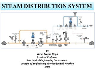
  • 1. By Varun Pratap Singh Assistant Professor Mechanical Engineering Department College of Engineering Roorkee (COER), Roorkee India STEAM DISTRIBUTION SYSTEM
  • 3. A
  • 4.
  • 5.
  • 6.
  • 7.
  • 8.
  • 9. Guidelines for Proper Drainage and Layouts of Steam Lines
  • 10.
  • 11.
  • 12.
  • 13.
  • 14.
  • 15.
  • 16.
  • 17.
  • 18.
  • 19.
  • 20.
  • 21.
  • 22.
  • 23. Thermost​atic Steam Traps Liquid expansion steam trap This is one of the simplest thermostatic traps and is shown in Figure. An oil filled element expands when heated to close the valve against the seat. The adjustment allows the temperature of the trap discharge to be altered between 60°C and 100°C, which makes it ideally suited as a device to get rid of large quantities of air and cold condensate at start-up.​ • The temperature of saturated steam varies with pressure. • Figure shows the saturation curve for steam, together with the fixed temperature response line (X - X) of the liquid expansion trap, set at 90°C. • It can be seen from Figure that when the pressure is at pressure P1, condensate would have to cool by only a small amount ( T1), and trapping would be acceptable. However, if pressure is increased to P2 then condensate has to cool more ( T2) to pass through the steam trap. This cooling can only occur in the pipe between the process and trap, and if the trap discharge temperature remains constant, the process will waterlog.
  • 24. Typical application Because of its fixed temperature discharge characteristic, the liquid expansion trap may be usefully employed as a ‘shutdown drain trap’. Here, its outlet must always point upwards, as illustrated in Figure 11.2.3, to enable continuous immersion of the oil filled element. As the trap can only discharge between 60°C - 100°C it will only normally open during start-up. It can be installed alongside a mains drain trap which would normally be piped to a condensate return line. Advantages of the liquid expan​​sion steam trap: • Liquid expansion traps can be adjusted to discharge at low temperatures, giving an excellent ‘cold drain’ facility. • Like the balanced pressure trap, the liquid expansion trap is fully open when cold, giving good air discharge and maximum condensate capacity on ‘start-up’loads. • The liquid expansion trap can be used as a start-up drain trap on low pressure superheated steam mains where a long cooling leg is guaranteed to flood with cooler condensate. It is able to withstand vibration and water hammer conditions. Disadvantages​ of the liquid expansion steam trap: • The flexible tubing of the element can be destroyed by corrosive condensate or superheat. • Since the liquid expansion trap discharges condensate at a temperature of 100°C or below, it should never be used on applications which demand immediate removal of condensate from the steam space. • If the trap is to be subjected to freezing conditions the trap and its associated pipework must be well insulated. • The liquid expansion trap is not normally a trapping solution on its own, as it usually requires another steam trap to operate in parallel. However, it can often be used where start-up rate is not an important consideration, such as when draining small tank heating coils.
  • 25. Balanced pressure steam trap A large improvement on the liquid expansion trap is the balanced pressure trap, shown in Figure. Its operating temperature is affected by the surrounding steam pressure. The operating element is a capsule containing a special liquid and water mixture with a boiling point below that of water. In the cold conditions that exist at start-up, the capsule is relaxed. The valve is off its seat and is wide open, allowing unrestricted removal of air. This is a feature of all balanced pressure traps and explains why they are well suited to air venting. As condensate passes through the balanced pressure steam trap, heat is transferred to the liquid in the capsule. The liquid vaporizes before steam reaches the trap. The vapor pressure within the capsule causes it to expand and the valve shuts. Heat loss from the trap then cools the water surrounding the capsule, the vapor condenses and the capsule contracts, opening the valve and releasing condensate until steam approaches again and the cycle repeats (Figure 11.2.5). The differential below steam temperature at which the trap operates is governed by the concentration of the liquid mixture in the capsule. The ‘thin-walled’ element gives a rapid response to changes in pressure and temperature. The result is the response line as illustrated in Figure.
  • 26. Early bellows type elements of non-ferrous construction were susceptible to damage by water hammer. The introduction of stainless steel elements improved reliability considerably. Advantages of the balanced pressure steam trap: • Small, light and has a large capacity for its size. • The valve is fully open on start-up, allowing air and other non-condensable gases to be discharged freely and giving maximum condensate removal when the load is greatest. • This type of trap is unlikely to freeze when working in an exposed position (unless there is a rise in the condensate pipe after the trap, which would allow water to run back and flood the trap when the steam is off). • The modern balanced pressure trap automatically adjusts itself to variations of steam pressure up to its maximum operating pressure. It will also tolerate up to 70°C of superheat. • Trap maintenance is simple. The capsule and valve seat are easily removed, and replacements can be fitted in a few minutes without removing the trap from the line. Disadvantages of the balanced pressure steam trap: • The older style balanced pressure steam traps had bellows which were susceptible to damage by water hammer or corrosive condensate. Welded stainless steel capsules introduced more recently, are better able to tolerate such conditions. • In common with all other thermostatic traps, the balanced pressure type does not open until the condensate temperature has dropped below steam temperature (the exact temperature difference being determined by the fluid used to fill the element). This is clearly a disadvantage if the steam trap is chosen for an application in which waterlogging of the steam space can not be tolerated, for example; mains drainage, heat exchangers, critical tracing.
  • 27. Bimetallic steam trap As the name implies, bimetallic steam traps are constructed using two strips of dissimilar metals welded together into one element. The element deflects when heated. (Figure 11.2.8): There are two important points to consider regarding this simple element: • Operation of the steam trap takes place at a certain fixed temperature, which may not satisfy the requirements of a steam system possibly operating at varying pressures and temperatures. • •Because the power exerted by a single bimetal strip is small, a large mass would have be used which would be slow to react to temperature changes in the steam system. • The performance of any steam trap can be measured by its response to the steam saturation curve. The ideal response would closely follow the curve and be just below it. A simple bimetal element tends to react to temperature changes in a linear fashion. • Figure 11.2.9 shows the straight line characteristic of a simple bimetal element relative to the steam saturation curve. As steam pressure increases above P1, the difference between steam saturation temperature and trap operating temperature would increase. Waterlogging increases with system pressure, highlighting the trap’s inability to respond to changing pressure conditions.
  • 28. It needs to be noted that at pressures below P1, the steam trap operating temperature is actually above the saturation temperature. This would cause the steam trap to pass steam at these lower pressures. It may be possible to ensure the steam trap is adjusted during manufacture to ensure that this portion of the saturation curve is always above the operating line. However, due to the linear action of the element, the difference between the two would increase even more with system pressure, increasing the waterlogging effect. Clearly, this is not a satisfactory operation for any steam trap, and various attempts have been made by manufacturers to improve upon the situation. Some use combinations of two different sets of bimetal leaves in a single stack, which operate at different temperatures. Advantages of the bimetallic steam trap: • Bimetallic steam traps are usually compact, yet can have a large condensate capacity. • The valve is wide open when the steam trap is cold, giving good air venting capability and maximum condensate discharge capacity under 'start-up' conditions. • As condensate tends to drain freely from the outlet, this type of steam trap will not freeze up when working in an exposed position. The bodies of some bimetallic steam traps are designed in such a way that they will not receive any damage even if freezing does occur. • Bimetallic steam traps are usually able to withstand water hammer, corrosive condensate, and high steam pressures. • The bimetal elements can work over a wide range of steam pressures without any need for a change in the size of the valve orifice. • If the valve is on the downstream side of the seat, it will tend to resist reverse flow through the steam trap. However, if there is any possibility of reverse flow, a separate check valve should be fitted downstream of the trap. Disadvantages of the bimetallic steam trap: • As condensate is discharged below steam temperature, waterlogging of the steam space will occur unless the steam trap is fitted at the end of a long cooling leg, typically 1 - 3 m of unlogged pipe. • Bimetallic steam traps are not suitable for fitting to process plants where immediate condensate removal is vital for maximum output to be achieved. This is particularly relevant on temperature controlled plants. • Some bimetallic steam traps are vulnerable to blockage from pipe dirt due to low internal flow velocities.. • Bimetallic steam traps do not respond quickly to changes in load or pressure because the element is slow to react.​
  • 29.
  • 30.
  • 31.
  • 32. Figure. High-temperature condensate flashes immediately at the orifice outlet as it is discharged into a lower-pressure system. Figure. When condensate is discharged from 145 psig to atmospheric pressure, a tremendous amount of flash steam is generated. However, when condensate at the same pressure is discharged to a closed system at 44 psig, much less flash steam is generated.
  • 33.
  • 34.
  • 35. Figure . When steam enters a return system that is filled with cooler condensate, steam pockets form. Collapsing steam pockets create violent shock waves directed to a pipe wall, causing water hammer. Figure. The backflow of steam from a two-phase condensate transport line into an equipment discharge pipe full of condensate discharging overhead can create water hammer — usually near the convergence point.
  • 36. Figure 13. Water hammer can be worse in vertical pipes than in horizontal piping. A vertical head of water above the steam pocket can exert additional pressure on the pocket, and, when the pocket collapses, the accelerating mass of the column of water can exacerbate the shock waves. Figure . Water hammer may occur wherever flash steam or live steam mixes with low-temperature condensate, if the condensate pulls sufficient heat from the steam and causes the pocket to collapse rapidly.
  • 37. Sparge pipes, which can break up flash steam into small bubbles, can be installed if it is necessary to discharge into a mostly liquid densate line. con Flash steam from condensate should be vented through a flash vessel. A flash vessel can mitigate severe hammering in a condensate return header, and can also be used for low-pressure flash recovery where the system equipment allows for some backpressure. Water hammer may be generated by different steam or flash steam sources, far from or upstream of the convergence point of transport piping. In such cases, pinpointing the cause can be challenging, but it is always wise to first check for leaking traps or open bypass lines.