Inlet system of an IC engine by Razin Sazzad Molla
•
3 recomendaciones•956 vistas

This presentation was part of the course requirements of MEC 401 (Internal Combustion Engines) which I took in fall 2016. I made all the slides (participants in my group never works lol) and here I am uploading for the public if it can be of any help. Contact me for any info if needed. ==================== Razin Sazzad Molla 13107010@iubat.edu ====================

Recomendados
Más contenido relacionado
La actualidad más candente
La actualidad más candente (20)
Similar a Inlet system of an IC engine by Razin Sazzad Molla
Similar a Inlet system of an IC engine by Razin Sazzad Molla (20)
Más de Razin Sazzad Molla
Último
Último (20)
Inlet system of an IC engine by Razin Sazzad Molla
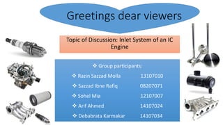
- 1. Greetings dear viewers Topic of Discussion: Inlet System of an IC Engine Group participants: Razin Sazzad Molla 13107010 Sazzad Ibne Rafiq 08207071 Sohel Mia 12107007 Arif Ahmed 14107024 Debabrata Karmakar 14107034
- 2. Topics covered: Overview of IC engines Inlet system and its significance Inlet system of SI engines Carburetor function Inlet system of CI engines Ignition systems Injection pumps and injectors Intake manifold and valves Camshaft mechanism Starting system Engine governors
- 3. Overview of IC Engines IC engines or Internal Combustion Engines are mechanical devices that produces mechanical power by rotating shaft using the derived heat energy from burnt fuel in the presence of oxygen of the atmospheric air and in which the air fuel combustion takes place inside the cylinder of the engine. IC engines can be of 2 types depending upon the movement of the energy transmitting member. One is the reciprocating type in which linear motion of the pistons is converted to rotary motion of the crank shaft and the other type is rotary engines where we have rotors to produce motions. IC Engines are broadly classified into many groups depending upon a lot of factors. Take for instance there are spark ignition & compression ignition engines based on the method of igniting the working fluid. Depending upon working cycles there are basically two major types, engines that work on otto cycle and engines that work on diesel cycle. There are also 2 stroke & 4 stroke cycle engines. All IC engines converts the chemical energy stored in hydrocarbon fossil fuel to mechanical work. This is the principle of all engines. About only 20% is used to propel the vehicle, 80% is lost to friction, aerodynamic drag, accessory operation or simply heat dissipated to the environment/cooling system SI engine: Uses petrol/gasoline(octane number 87-89), low compression ratio(8:1 to 12:1) Energy content 34.6 MJ/litre high rpm,less torque CI Engines: Uses Diesel(cetane number between 40&60) compression ratio 14:1 to 25:1 38.6 MJ/litre low rpm high torque
- 4. Inlet system and its significance The combustion of fuel in internal combustion engine is a fast exothermic reaction in the gaseous phase where oxygen obtained from air is usually one of the reactants. In actual practice the working fluid is considered to be a mixture of air fuel and residual gases(fuel-air cycle). For an engine to perform properly and most efficiently the system has to provide air fuel mixture at an exact time and at an exact amount in all the cylinders so the combustion takes place as designed. The inlet system of an IC engine consists of all the interconnected components that perform the task of drawing clean air and mixing it with fuel vapor at varying proportions and permitting it into all the chambers at proper time and through the ignition process oxidizing it. Typical components associated with Inlet system: Air filter, carburetor, throttle valve, oil tank, oil filter, oil pump, spark plug, glow plug, pressure pump, injector, distributor, fuel supply unit, common rail system, intake manifold, gaskets, poppet valves, cam shaft assembly(cam lobes, cam timing belt, rocker arm, camshaft sprocket, tensioner), ignition system (coil ignition, magneto ignition), alternator, Electronic control unit, starter motor, sensors. Engine subsystems: Air & exhaust system, Fuel system, Ignition system, Cooling subsystem, Lubrication system, Electronic system, Mechanical system, Governing subsystem In the following slides our discussion will be limited to the inlet system of the conventional IC engines only.
- 5. Inlet system of petrol engines Typical Fuel System Components that supply clean fuel to the fuel metering system (fuel pump, fuel pipes, fuel filters). 1. Fuel Supply System Components that supply controlled clean air to the engine (air filter, ducting, valves). 2. Air Supply System Components that meter the correct amount of fuel (and air) entering the engine (injectors, pressure regulator, throttle valve). 3. Fuel Metering System
- 6. Petrol engine- carburetor fuel system
- 7. Engine Fuel System (SI Petrol) • Fuel Tank – normally positioned in the rear boot area, The fuel tank may be made from pressed steel and coated inside to prevent corrosion, or a synthetic rubber compound or flame resistant plastic. Inside the fuel tank is normally located the fuel gauge sender unit and electrically driven fuel pump with a primary filter in a combined module. The fuel tank is pressurised to about 2 psi to prevent fuel vaporization and pollution. The fuel tank is vented through its own venting system and the engine managements emission control systems again to control pollution. • Fuel pipes – These can be made from steel or plastic and are secured by clips at several points along the underside of the vehicle. To allow for engine movement and vibration, rubber hoses connect the pipes to the engine.
- 8. Engine Fuel System (SI Petrol) • Fuel Filters – to prevent dirt and fluff entering the fuel pump a filter is fitted on the suction side of the pump. On the pressure side of the pump a secondary filter is used, this is a much finer filter in that it prevents very small particles of dirt reaching the carburettor or fuel injection equipment. • Air Filters – air cleaners and silencers are fitted to all modern vehicles. Its most important function is to prevent dust and abrasive particles from entering the engine and causing rapid wear. Air filters are designed to give sufficient filtered air, to obtain maximum engine power. The air filter/cleaner also acts as a flame trap and silencer for the air intake system. • Fuel Pump – this supplies fuel under high pressure to the fuel injection system, or under low pressure to a carburettor. • Carburettor – this is a device which atomizes the fuel and mixes it which the correct amount of air, this device has now been superseded by modern electronic fuel injection.
- 10. • Float chamber – to set and maintain the fuel level within the carburettor, and to control the supply fuel to the carburettor venturi. • Operation – when air passes through the venturi due to the engines induction strokes, it creates a depression (suction), around the fuel spray outlet. Atmospheric pressure is acting on the fuel in the float chamber, the difference in theses pressures causes the fuel to flow from the float chamber, through the jet and into the stream. This causes the petrol to mix with the air rushing in to form a combustible mixture. The required air fuel ratio can be obtained by using a jet size which allows the correct amount of fuel to flow for the amount of air passing through the Defects of the simple carburettor • As engine speed increases, air pressure and density decreases i.e. the air gets thinner, however the quantity of fuel increases i.e. greater pressure exerted on the fuel, this causes the air/fuel mixture to get progressively richer (to much fuel). • As the engine speed decreases, the air/fuel mixture becomes progressively weaker. Some form of compensation is therefore required so that the correct amount of air and fuel is supplied to the engine under all operating conditions.
- 11. Petrol Operation of the Venturi The Choke Valve is used to provide a rich air/fuel ratio for cold starting Choke Valve closed The Float Chamber The Throttle Valve controls the amount of air fuel mixture entering the engine and therefore engine power The Simple Carburettor
- 16. Air Fuel Ratio • Fuel mixture strengths – petrol will not burn unless it is mixed with air, to obtain the best possible combustion of the fuel, which should result in good engine power and fuel consumption and low emissions (pollution), the air fuel ratio must be chemically correct i.e. the right amount of air and fuel must be mixed together to give an air fuel ratio of 14.7 to 1 by mass. This is referred to as the stoichiometric air fuel ratio, this ratio can also be describe by the term Lambda. Lambda is the Greek word meaning ‘air’. When their is more air present than fuel in the air fuel mixture, it is said to be ‘weak’ or ‘lean’ i.e. not enough fuel e.g. a ratio of 25 to 1, this results in a Lambda reading of more than 1.When their is not enough air present, the mixture is referred to as ‘rich’ e.g. a air fuel ratio of 8 to 1, in this case Lambda equals less than 1. • Weak/lean air/fuel mixtures – can result in low fuel consumption, low emissions (pollution), however, weak air fuel mixtures can also result in poor engine performance (lack of power) and high engine temperatures ( because the fuel burns more slowly) • Rich air/ fuel mixtures – can result in greater engine power, however this also results in poorer fuel consumption and greatly increased emissions (pollution)
- 17. Engine (S I) Fuel System • ECU – Electronic control unit- This contains a computer which takes information from sensors and controls the amount of fuel injected by operating the injectors for just the right amount of time. The ECU also controls the operation of the ignition and the other engine rated systems. • Air flow/mass meter – A sensor used to tell the ECU how much air is being drawn into the engine. • MAP sensor – Manifold absolute pressure sensor. This senses the pressure in the engines inlet manifold, this gives an indication of the load the engine is working under. • Speed/crankshaft sensor – This tells the ECU has fast the engine is rotating and sometimes the position of the crankshaft. • Temperature sensor – Coolant temperature is used determine if more fuel is needed when the engine is cold or warming up. • Lambda sensor – A sensor located in the exhaust system which tells the ECU the amount of oxygen in the exhaust gases, form this the ECU can determine if the air/fuel ratio is correct. • Fuel pump – A pump, normally located in the fuel tank, which supplies fuel under pressure to the fuel injectors.
- 18. Engine S I Fuel System • Fuel filter – keeps the fuel very clean to prevent the injectors becoming damaged or blocked. • Fuel rail – A common connection to multi point injectors, acts a reservoir of fuel (small tank of fuel). • Injector – A electrical device which contains a winding or solenoid. When turned on by the ECU, the injector opens and fuel is sprayed into the inlet manifold, or into the combustion chamber itself. • Idle actuator – A valve controlled by the ECU which controls the idle speed of the engine. Electronic control unit
- 19. Introduction to Electronic Petrol Throttle/Single Point Fuel Injection Systems The Carburettor has now been replaced with petrol injection systems. These systems supply the engine with a highly atomized mixture of air and fuel in the correct air/fuel ratio. This has the following advantages over the carburettor systems Lower exhaust emissions (pollution) Better fuel consumption Smoother engine operation and greater power Automatic adjustment of the air/fuel ratio to keep the vehicles emissions (pollution) to a minimum.
- 20. Air drawn in by the engine Fuel Supply Throttle Body Throttle Valve Inlet Manifold Fuel Injector (one off) The Engine Throttle Body/Single Point S.I. Fuel Injection
- 21. Single Point Electronic Fuel Injection (EFI) Systems EFI systems are classified by using the point of injection. A fuel injector (may be 2) is located in a throttle body assembly that sits on top of the inlet manifold. Fuel is sprayed into the inlet manifold from above the throttle valve, mixing with incoming air. Fuel quantity, how much fuel is injected is controlled by an ECU. Single Point (Throttle Body) Fuel Injection ECU Fuel in Inlet manifold Air in TB injector
- 22. Needle valve Electrical connector Fuel filter Fuel in SpringArmatureNozzle/jet Solenoid coil Electronic Fuel Injector Operation An injector sprays fuel into the inlet manifold by use of a solenoid coil. When the coil is switch on by the ECU, it pulls the armature/needle valve away from the nozzle, allowing pressurized fuel into the engine. When the coil is not switched on, the spring pushes the armature/needle against the nozzle, no fuel is injected into the inlet manifold Injectors are more precise and efficient than carburettors.
- 23. Protective cap with gas intake slots Wires to ECU Protective cap with gas intake slots Wires to ECU Reference voltage Engine coolant temperature sensor +V V 0V Reference voltage Reference voltage Engine coolant temperature sensor +V V 0V +5V 0V TPS +5V 0V TPSTPS ECU IAC valve Throttle valve Air in Solenoid coil ECU IAC valve Throttle valve Air in Solenoid coil The ECU (Brain) receives Information from varies sensors. From this information it works out how much fuel the engine needs Outputs Single Point Injection Sensor Inputs
- 24. Air drawn in by the engine Fuel Injectors Throttle Valve Fuel Supply Inlet Manifold Injectors Engine Multi – Point S.I. Fuel Injection
- 25. Typical S.I. Fuel System Layout (Simplified) Fuel Tank Fuel Pump Fuel Filters Carburettor Or Single Point Throttle Body Housing Fuel Injector or Carburettor Venturi Fuel Not used is returned to the fuel tank Inlet Manifold Engine Combustion Chamber Fuel Pressure Regulator EFI Only
- 26. Ignition Systems Ignition process in Petrol Engines requires an electric spark produced at the spark plug. This spark is generated by an electric discharge produced by the ignition system. Ignition systems in petrol engines are classified as: 1.Battery ignition system. 2.Magneto ignition system The difference between the two systems is in the source of primary voltage. Basic requirements of an ignition systems A source of electrical energy A device for boosting the low voltage to produce high voltage A device for timing and distributing the high voltage to each spark plug Battery ignition system It is also called coil ignition system. The source of energy to the primary windings is a 6V or 12V battery. As the number of windings in the secondary is 50 to 100 times more than that of the primary , the output voltage induced will be of the order of 10000v to 20000V. Magneto Ignition System The source of energy is either rotating magnets with fixed coils or rotating coils with fixed magnets. The rapid collapse and reversal of magnetic field induces a very high voltage in the secondary winding. It is generally employed in racing cars, motor cycles etc.
- 29. Spark plug The spark plug ignite the suctioned and compressed fuel- air mixture due to arcing between the electrodes. Function: The ignition voltage travels to the spark plug from directly connected ignition coils or over the ignition lines from the Ignition coils causing arcing in the air gap between the center and ground electrodes. Spark plug is located in the cylinder head. It ignites the air and fuel mixture. Has center and side electrodes, with an air gap between them. Centre electrode receives coil voltage. Side electrode is grounded. High voltage jumps the air gap, creating a spark. Insulator prevents high voltages from shorting to ground.
- 30. INLET SYSTEM OF DIESEL ENGINE Air intake systems vary greatly from vendor to vendor but are usually one of the two types, wet or dry. In a wet filter intake system as shown in figure the air is sucked or bubbled through a housing that holds a bath of oil such that the dirt In the air is removed by the oil in filter. The air then flows through a screen type material to ensure any entrained oil is removed from the air. In a dry filter system paper cloth or a metal screen material is used to catch and trap dirt before it enters the engine.(similar to the type used in automobiles) In addition to cleaning the air the intake system is designed to intake fresh air from as far as practicable, usually just outside the engines building or enclosure. This provides the engine with a supply of air that has not been heated by the engine’s own waste heat. The reason for ensuring that the engines air supply is as cool as possible is that cool air is more dense than hot air. This means that cool air has more oxygen per unit volume than hot air. Thus cool air provides more oxygen per cylinder charge than hot less dense air. More oxygen means a more efficient fuel burn and more power. After being filtered the air is routed by the intake system into the engines intake manifold or air box. The manifold or air box is the component that directs the fresh air to each of the engines intake valve or port. If the engine is turbocharged or supercharged the fresh air will be compressed with a blower and possibly cooled before entering the intake manifold or air box. The intake system also serves to reduce the airflow noise.
- 32. FUEL SYSTEM OF DIESEL ENGINE During engine operation, the fuel is supplied by gravity from fuel tank to the primary filter where coarse impurities are removed. From the primary filter, the fuel is drawn by fuel transfer pump and is delivered to fuel injection pump through second fuel filter. The fuel injection pump supplies fuel under high pressure to the injectors through high pressure pipes. The injectors atomize the fuel and inject it into the combustion chamber of the engine. The fuel injection pump is fed with fuel in abundance. The excess fuel is by-passed to the intake side of the fuel transfer pump through a relief valve. The main components of the fuel system in diesel engine are: (1) fuel filter (2) fuel lift pump (3) fuel injection pump (4) atomizers and (5) high pressure pipe. Two conditions are essential for efficient operation of fuel system: (i) The fuel oil should be clean, free from water, suspended dirt, sand or other foreign matter, (ii) The fuel injection pump should create proper pressure, so that diesel fuel may be perfectly atomized by injectors and be injected in proper time and in proper quantity in the engine cylinder.
- 33. Layout of diesel fuel system
- 34. FUEL LIFT PUMP (FEED PUMP OR TRANSFER PUMP) It is a pump, which transfers fuel from the fuel line to the fuel injection pump. It is mounted on the body of fuel injection pump. It delivers adequate amount of fuel to the injection pump. The pump consists of: (I) body (2) piston (3) inlet valve and (4) pressure valve. The valves are tightly pressed against their seats by springs. The piston is free to slide in the bore. The fuel contained in the space below the piston is forced to flow through secondary fuel filter to the injection pump. At the same time downward movement of the piston creates a depression in the space above the piston which, causes the fuel to be drawn in the transfer pump from the fuel tank through the inlet valve and the primary filter. Bosch-Fuel-Lift-Pump
- 35. FUEL INJECTING PUMP It is a pump, which delivers metered quantity of fuel to each cylinder at appropriate time under high pressure. Tractor engines may use two types of fuel injection pump: (i) Multi-element pump and (ii) Distributor (Rotary) type pump. Fuel Injector: It is the component, which delivers finely atomized fuel under high pressure to the combustion chamber of the engine. Modern diesel engines use fuel injectors, which have multiple holes. Main parts of injector are: nozzle body and needle valve. The nozzle body and needle valve are fabricated from alloy steel. The needle valve is pressed against a conical seat in the nozzle body by a spring. The injection pressure is adjusted by adjusting the screw. FUEL INJECTION SYSTEM Diesel fuel is injected in diesel engine through injectors with the help of fuel injection pump. The system using injectors, fuel injection pump, fuel filter, and fuel lines is called fuel injection system. The main functions of fuel injection system are: (i) To measure the correct amount of fuel required by engine speed and load, (ii) To maintain correct timing for beginning and end of injection, (iii) To inject the fuel into the combustion space against high compression pressure. (iv) To atomize the fuel for quick ignition.
- 36. Based on the methods used to produce the required pressure for atomization of the fuel process of fuel injection in diesel engine is of two types: (i) Air injection (ii) Solid injection. Air injection: In this process, the engine uses compressed air to force the fuel into the cylinder. It is a bulky system and hence it is not considered very suitable for vehicles and tractors. It is mostly used on heavy-duty stationary engines. Solid injection: A high-pressure pump is used for forcing the fuel into the combustion chamber. Depending upon the location of the fuel pumps, the grouping, the method of actuating the pumps and the methods used to meter the fuel the solid injection system can be classified as follows: 1. Individual pump system or the divided fuel feed device 2. Unit injector system or the undivided fuel feed device 3. Distributor system 4. Common rail system Fuel injection system components 1. Pumping elements 2. Metering elements 3. Metering control 4. Distributing elements 5. Timing controls 6. Mixing elements
- 37. Individual pump system or the divided fuel feed device Each cylinder is provided with one pump and one injector. The injector is located on the cylinder while the pump is on the side of the engine. Jerk pump is used.
- 38. Unit injector system or the undivided fuel feed device The high pressure pipeline connecting the individual pump and the associated injector can be avoided by the design of a unit injector.in this system the pump and injector nozzle are combined in one housing. Each cylinder has one of these injector units. Fuel is brought up to the pump by a low pressure pump. This system requires a pushrod and a rocker arm to actuate the plunger and injects the fuel into the cylinder at the proper time.
- 39. The distributor system A single pump for compressing the fuel and a dividing device to distribute the fuel to the cylinders are used.
- 40. Common rail system The fuel from the fuel storage tank is drawn through the primary fuel filters by a low pressure fuel feed pump. The discharge from this pump enters the high pressure fuel injection pump. This pump serves only to deliver fuel under high pressure to a common rail called the header with the pressure held constant by a pressure regulating valve.
- 41. Inline injection pump Traditional inline injection pump Have a pump element (plunger, cylinder) for each engine cylinder - Pump elements in line disposal Body - Crankcase, Camshaft, Feeding pump (or not) ,Pushers (or not), Visit window ,Gear rack, Pump elements (plungers, cylinder, gear), Feeding collector, Retention valves, Automatic speed regulator Camshaft - It have the same rotation as the engine camshaft (one turn for two turns of the crankshaft) Causes an linear movement on the plungers , Plungers - Push the fuel in the direction of the injector - Gear rack -Causes an rotation movement on the plungers that is function of the accelerator pedal - Pump elements - Control the amount of fuel that goes to the injector
- 43. Basic operation he eccentric on the camshaft causes constant linear movement of the pushers - the plungers, by the action of the pushers, push the fuel in the direction of the retention valve - the pressure is high enough to open the retention valve and the fuel is conducted by pipes to the injectors - the amount of fuel is controlled by the gear rack. The gear rack causes an rotation movement to the plunger that is function of the accelerator pedal The plunger has cannelures around it self to fuel flow, and the position of the rack determines the position of the plunger that determines the amount of fuel injected. The end of injection occurs when the cannelure of the plunger reaches a position that makes connection between the cylinder and the feeding collector, balancing the pressure
- 44. Radial rotary injection pumpUsed on small diesel engines - Low volume and weight - High efficiency An example is VR BOSCH radial rotary injection pump - One pump element for all the engine cylinders - Presence of internal sensors (fuel temperature, rotation angle) - Has a pump control unit, independent from the engine control unit. There is a high pressure side and a low pressure side. Basic operation -Distributor functions - Send fuel to plungers - Time duration in close position of electro-valve determines the injection flow -Send fuel to injectors -The plungers are pressed by cam -Fuel high pressure generated - Distributor rotates to injector flow position
- 45. Electronic Diesel Control The EDC is divided into these main groups of components: Electronic sensors for registering operating conditions and changes. A wide array of physical inputs is converted into electrical signal outputs. Actuators or solenoids which convert the control unit's electrical output signal into mechanical control movement. ECM (Electronic Control Module ) or Engine ECU (Electronic Control Unit) with microprocessors which process information from various sensors in accordance with programmed software and outputs required electrical signals into actuators and solenoids. EDC distributor injection pump EDC injection inline pumpEDC control unit EDC accelerator pedal assembly
- 46. Fuel injector Nozzle refers to the part of the nozzle body/needle assembly which interfaces with the combustion chamber of the engine. Terms like P-Type, M-Type, or S- Type nozzle refer to standardized dimensions of nozzle parameters, as per ISO specifications. Nozzle holder or injector body refers to the part the nozzle is mounted on. In conventional injection systems this part mainly served the nozzle mounting and nozzle needle spring preloading function. In common rail systems, it contains the main functional parts: the servo-hydraulic circuit and the hydraulic actuator (electromagnetic or piezoelectric). Injector commonly refers to the nozzle holder and nozzle assembly. Fuel injector Under high pressure, the temperature of the diesel fuel increases to a point where the fuel self-combusts. In cold weather however, this temperature is not always achieved and glow plugs assist by heating the air-fuel mixture to assist in cold starting. Glow plug
- 47. Intake Manifolds The primary function of the intake manifold is to evenly distribute the combustion mixture (or just air in a direct injection engine) to each intake port in the cylinder head(s). Even distribution is important to optimize the efficiency and performance of the engine. It may also serve as a mount for the carburetor, throttle body, fuel injectors and other components of the engine. The design and orientation of the intake manifold is a major factor in the volumetric efficiency of an engine. Modern intake manifolds usually employ runners, individual tubes extending to each intake port on the cylinder head which emanate from a central volume or "plenum" beneath the carburetor. The purpose of the runner is to take advantage of the Helmholtz resonance property of air.
- 48. Engine Intake Valves(Poppet valve) A poppet valve (also called mushroom valve) is a valve typically used to control the timing and quantity of gas or vapor flow into an engine. It consists of a hole, usually round or oval, and a tapered plug, usually a disk shape on the end of a shaft also called a valve stem. The portion of the hole where the plug meets with it is referred to as the 'seat' or 'valve seat'. The shaft guides the plug portion by sliding through a valve guide. Poppet valves are used in most piston engines to open and close the intake and exhaust ports in the cylinder head. Three-valve cylinder head: This has a single large exhaust valve and two smaller intake valves. Four-valve cylinder head: This is the most common type of multi- valve head, with two exhaust valves and two similar (or slightly larger) inlet valves. A cylinder head of a four valve engine. ( Nissan VQ engine )
- 49. Camshafts mechanism Primary purpose is to operate the valve train. The camshaft may also operate the following: ■ Mechanical fuel pump ■ Oil pump ■ Distributor The cam is driven by timing gears, chains, or belts located at the front of the engine. The gear or sprocket on the camshaft has twice as many teeth, or notches, as the one on the crankshaft. This results in two crankshaft revolutions for each revolution of the camshaft. The camshaft turns at one-half the crankshaft speed in all four-stroke-cycle engines. Push Rods and Rocker Arms: Push rods are used only on cam-in-block engines. They transmit the lifter motion to the rocker arm. Rocker arms are pivoting levers that convert the upward movement of the push rod or lifter into downward movement of the valve. The camshaft is supported in the block by camshaft bearings and driven by the crankshaft with a gear or sprocket and chain drive. On overhead cam engines, the camshaft is installed on top of the cylinder head. It opens the valves from above. In some overhead cam engines, the lifter is placed between the cam lobe and the rocker arm. In many cases, the rocker arm is directly operated by the camshaft. A hydraulic lash adjuster, similar in operation to a hydraulic lifter, maintains the proper valve clearance
- 51. Starting system The starter motor drives the engine through a pinion gear that engages the ring gear on the flywheel. The starting system: •Uses a powerful electric motor to drive the engine at about 200 RPM (fast enough to allow the fuel and ignition systems to operate). •Drives the engine through a pinion gear engaged with a ring gear on the flywheel. •Disengages as soon as the engine starts. Starting System Components: These components make up a typical Toyota starting system: •Starter motor •Magnetic switch •Over-running clutch •Ignition switch contacts •Park/neutral position (A/T) or clutch start (M/T) switch •Clutch start cancel switch (on some models) •Starter relay
- 52. Engine governor Governor is a mechanical device which is used to regulate the mean speed of the engine, when there are variations in the load. When load on the engine varies, the configuration of the governor changes and it controls the supply of the fuel to the engine. When load on the engine increases, its speed decreases, so it becomes necessary to increase the supply of the working fluid (ex petrol or diesel) to the engine. On the other hand when the load on the engine decreases, the governor’s speed increases, so it requires to decrease the supply of the fuel. When the speed of the governors increases, its sleeve moves in upward direction, which is connected to a throttle valve through a bell crank lever. This upward motion of the sleeve operates the valve to decrease the supply of the fuel. And when the speed of the governor decreases due to the increase in the load, the sleeve move downward, this made the valve to open to a larger extent and increases the fuel supply.
- 53. The End