Millau Bridge (Operations Management)
•Descargar como PPT, PDF•
16 recomendaciones•7,095 vistas

The Millau Viaduct in southern France is the highest road bridge in the world at 300m tall. It has 7 pillars and spans the Tarn Valley. British architect Norman Foster designed the bridge to appear delicate like a butterfly. Construction involved raising the huge concrete pillars with a climbing system. The 36,000 ton steel deck was then launched section by section onto the pillars. Steel pylons weighing 650 tons each were erected on top of the pillars to support cables. The privately financed bridge cost €394 million to build and opened in 2004, cutting travel time across the region.

Recomendados
Más contenido relacionado
La actualidad más candente
La actualidad más candente (20)
Similar a Millau Bridge (Operations Management)
Similar a Millau Bridge (Operations Management) (20)
Más de Rohan Negi
Más de Rohan Negi (10)
Último
Último (20)
Millau Bridge (Operations Management)
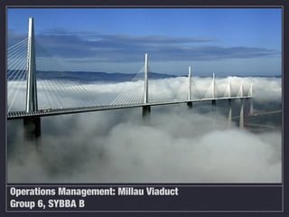
- 1. Operations Management: Millau Viaduct Group 6, SYBBA B
- 2. Millau Viaduct The Millau Viaduct is in southern France and crosses the River Tarn in the Massif Central mountains. It was designed by the British architect Lord Foster and at 300m (984 feet) it is the highest road bridge in the world, weighing 36,000 tonnes. The central pillar is higher than the famous French icon, the Eiffel Tower. The Bridge opened in December 2004 and is possibly one of the most breath taking bridges ever built.
- 3. • The bridge towers above the Tarn Valley and the aim of Lord Foster was to design a bridge with the ‘delicacy of a butter fly’. • Lord Foster designed a bridge that enhances the natural beauty of the valley, with the environment dominating the scene rather than the bridge. • The bridge appears to float on the clouds despite the fact that it has seven pillars and a roadway of 1½ miles in length.
- 4. The bridge was opened by President Jacques Chirac. In his speech he praised the design saying that it was a ‘monument to French engineering genius’ and ‘a miracle of equilibrium’. The aim is to cut the travelling time to southern France, removing the bottle neck at Millau, through the completion of the motorway between Paris and the Mediterranean.
- 5. The bridge was entirely privately financed and cost 394 million euros (272 million pounds, 524 million dollars). The builders, Eiffage, financed the construction in return for a concession to collect the tolls for 75 years, until 2080. However, if the concession is very profitable, the French government can assume control of the bridge in 2044.
- 6. Construction of Millau Viaduct
- 7. Steel deck with multiple sub-bended spans. Steel deck with continuous spans of constant depth. Steel or concrete deck with multiple cables-stayed spans Concrete bridge including an arch with an opening 600m wide over the River Tarn Viaduct with continuous spans of variable depth in concrete or composite material
- 8. 7 piers P1 to P7 2 abutments C0 & C8 6 spans 342 m long 2 side -spans 204 m long
- 9. 6 STAGES OF CONSTRUCTION 1. Raising the piers 2. Throwing the deck 3. Joining the deck 4. Installing the pylons 5. The stays 6. Finishings
- 11. Piers - The piers are the towering part of the structure with the tallest one reaching over 245 meters tall. The piers hold the road way and the pylons. 1. The piers were constructed using reinforced concrete. The piers have the design of tapering down from top to bottom. The seven piers are identical except for the length due to the valley bottom. 2. The piers have been constructed using an automatic rail climbing system or ACS. The system required the bottom section the pier be constructed then the climbing system attached to rail secured to the pier. Allowing the system to move up the piers independently . 3. The ACS would pour 4 meter sections of concrete at a time allowing accurate pours and ensuring structural stability. 4. The ACS enabled the piers to be built on schedule. The system allowed for a correct pour each time it moved up the pier.
- 12. Pier Design The pier design : flexible piers at their base =strong distortion of the deck Pier design : piers with flexural rigidity at their base=Less distortion of the deck
- 13. Actual Pier Pier 2
- 15. Usage of Temporary Piers
- 16. 1. Once these temporary piers were erected, placement of the 36,000-ton (32,659 t) prefabricated deck began. 1. Placing the deck began in late February 2003. By March 26, 2004, the deck had progressed to the third pier. During the evenings of April 4 and 5, 2004, the deck arrived at the second pier with the last launch accomplished on May 28, 2004. 1. Decks were placed with the help of hydraulics from Enerpac. 1. Simply pushing this enormous weight over the top of the venerable piers would bring them crashing to the ground. The construction team made a launching system in which they use a series of launching systems to jack up the deck and inch it forward each system uses two wedge shape block on each side of the deck. the upper wedge is pulled forward by hydraulic system its slides up the slope of the lower wedge same time lifting the deck from it supports and advancing it 600 mm. the lower wedge then retracts dropping the deck to its support the upper wedge returns to its original position and the whole cycles begins again. Four of these devices are placed on each piers all programmed to work exactly at a same time. The result is they pick up the entire road way and move it forward. Every 4 minutes the deck advances 6mm across the valley.
- 17. Joining the deck
- 18. Moving the deck could be accomplished three ways: manual, semi-automatic and automatic. Manual mode was used for adjustments and any necessary instant corrections. In the semi-automatic mode, each movement was made step by step, or, in other words, raise, push, lower, and then withdraw. Automatic mode completed each entire launch cycle.
- 19. The technically advanced hydraulic system was designed to push the 27,35 m wide deck (with a capacity for six lanes plus hard shoulders) from both sides onto the seven concrete piers. During the launching process, the deck will be supported by seven temporary metal piers. The enormous yet at the same time “light” deck was pushed by means of hydraulic launching devices on each pier, which first lift and then push the deck. An adjustable nose structure at the end of the deck, allows the deck to land on each pier as it approaches it.
- 20. In all, 18 launches — six from the north side of the bridge and 12 from the south — were required to position the deck, with the last launch accomplished on May 28, 2004.
- 22. Seven pylons had to be raised Each of these steel pylons takes the form of an inverted Y, 77 metres high and weighing 650 tonnes. They were prefabricated on site and then raised this was quicker and reduced not only the risk of interruption because of strong winds but also the problems of safety Once the assembly and welding work was complete, the pylon is transported flat onto the viaduct deck by means of a special multi-axle lowered Kamag trailer weighing 200 tonnes. The pylon is manoeuvred into a vertical position using lifting towers rather than mobile cranes because of its speed, narrow confines of the deck, weather risks and safety requirements.
- 23. The time taken to lift a pylon is around 6-7 hours. All the operations involving the pylon, including loading, transportation, lifting and welding to the deck, and the lifting tower and putting it in position was at the rate of one pylon per week.
- 24. THE STAYS
- 25. Each pylon of the viaduct is equipped with a monoaxial layer of eleven pairs of stays laid face to face. Depending on their length, the stays were made of 55 to 91 high tensile steel cables, or strands, themselves formed of seven strands of steel Each strand has triple protection against corrosion and the stay-cables weight about 1,500 tons The exterior envelope of the stays is itself coated along its entire length with a double helical weatherstrip. The idea is to avoid running water which, in high winds, could cause vibration in the stays and compromise the stability of the viaduct. The stays were installed using a well-tried technique. After threading one strand in the outer protective sheath, it is pulled up on to the pylon to its final location. The strand is then fixed in the upper and lower anchorage points. A 'shuttle' then brings the other strands one by one, and they are then stretched to tension."
- 26. FINISHINGS The surface (the covering of the road) of the millau viaduct is the result of several months of research. It was designed to withstand any distortion of deck & provide the necessary qualities for comfortable motorway driving. It took less than four days work to lay it. Final finishing touches: electric lighting, signposts, operating systems, final road covering.
- 27. To make the world’s tallest bridge
- 29. What is material handling ? Material Handling is the movement, storage, control and protection of materials, goods and products throughout the process of manufacturing, distribution, consumption and disposal. The focus is on the methods, mechanical equipment, systems and related controls used to achieve these functions. Material handling is an integral part of any industrial activity as greater emphasis is laid on productivity, profitability as well as resource conservation and ecological preservation. Material handling plays a very crucial role in sustaining efficiency in financial and human resources.
- 30. Millau Bridge -Weight 242000 tonnes -Estimated life 120 years
- 31. MAJOR MATERIALS : 1. STEEL : Steel is used in many places where concrete was earlier used The cost of steel and concrete was about 390 million euros (520 million dollars). The project required about 19,000 metric tons of steel for the reinforced concrete, and 5,000 metric tons of pre-stressed steel for the cables and shrouds. The bridge is constructed out of 2,078 steel pieces made by the EIFFEL Company, the successor of the company that built the Eiffel Tower The deck and pylons are made of steel sheets of grade S355 and S460.
- 32. • All steel components were welded together, assembled and painted at ground level, and in many cases even in an indoor workshop. • This had a favorable effect on the quality of the finished pieces, on the safety of the workforce and on cost as steel is a recyclable metal
- 33. 2. CONCRETE : The project required about 127,000 m³ of concrete. The concrete of the abutments and piles amounted to 85 000 m3, 40 times the Eiffel Tower The massive piers are made from type B60 concrete, a high-strength concrete with durability characteristics more than its mechanical resistance. During construction of the bridge concrete pours were made 4m tall
- 34. 3. Stay Cable material : The stay cables are made from T15 strands of class 1,860MPa which are super-galvanized, sheathed, and waxed. The cables are protected by a white, aerodynamic sheath made from non- injected PEHD (high-density polyethylene) Developed by through a collaboration between Buonomo, Servant, Virlogeux, Cremer, Goyet and Del Forno
- 35. ENVIRONMENT FRIENDLY USE OF MATERIALS Steel was used in most places instead of concrete which reduced the use of trucks. Included a system for collecting and processing rainwater and other waste which would be accumulated during road washing Excess construction materials were carefully stored to use them for other operations - wood was sent to paper mills - oil and lubricants were sent for recycling Various sites of production zones had been selected with an intention to keep hedge and bush felling to the minimum
- 37. IDEA •The Millau Viaduct being one of the most extensive projects ever tackled by the construction industry faced huge challenges particularly due its location and enormous size. •CivilEngineer Michel Virlogeux ,was attempting to push the limits of engineering and create something that had never been done before when he came up with his idea for the design of the Millau Viaduct. With architect Sir Norman Foster he created a sweeping elegant design for the structure that would also be structurally sound.
- 38. •Thefinal design was without a doubt one of the most appealing ever before created and proved that “big doesn’t always have to look brawny.” •After 14 years of intense planning the construction began.
- 39. CONSTRUCTION MAJOR CHALLENGES: 1. Build the tallest bridge piers in the world. 2. Put a 36000 ton free way on top of them. 3. Erect 7 steel pylons each weights 700 tons. 4. Land
- 40. 1. PIERS • There are 7 piers that are numbered from the northern end of the valley. Number 1 was to cause problems because of steep slope. Number 2 was the tallest across the river number 3 was not much shorter from no. 2. Then 4, 5, 6 and 7 found the genital slope to the south. • 16000 tons of steel bars are used. The shape of each pair is complicated as a result each time they removed the section of red steel sheltering they have to change the shape of the mold to fit the profile of the next 4 meter section man handling these steel panels way up to 15 tons of piece is no picnic. And with the combine height of 7 piers totaling well over a kilometer they had to change the shape of the mold over 250 times. • Every 3 days each team on each pair went through this whole cycle then they repeated the process but it was time consuming.Month after month the piers climbed higher finally by November 2003 they reached their full height. At 245 meters pair 2 becomes the highest bridge pier in the world. The piers were exactly on the location where it had to be with 2cm deviation.
- 41. 2. Free way on top of them. • Second problem was putting a 36000 ton free way on top of the piers. Working at these heights could be lethal. Around 235 people died in the process. • Therefore the team decided to fabricate the entire rope deck on the safety of solid grounds instead of concrete, steel was used for the deck which in theory would be much safer then lifting concrete sections hundreds of meters in the position. EIFFEL, the steel firm took up the challenge. • This involved manufacturing 2200 separate sections weighing up to 90 tons and some of them 22 meters long. Their accuracy was measured with laser to within a fraction of a millimeter. The triangular side panel were welded on either side to create width for a 4 lane high way. They automated the manufacturing with a two headed welding robot and a plasma cutting machine each cutting pattern or template was programmed in to the computer then the machine automatically blazes its way through the steel.
- 42. 3. Erect the steel pylons • Another problem faced with construction was the need to eliminate error in position. • The pylons were of such enormous heights that being off even the slightest at the bottom of the pylon could spell disaster at the top of the pylon in the form of meters off the intended mark. • When considering the pylons, other challenges faced included: pouring the cement in a timely manner as to prevent from setting, hurricane grade winds faced by workers, and the intricate design of each pylon moving to the overall construction of the bridge. • This made constructing the platform a challenge all its own. Spans of this great length in the past have spelled disaster in the form of collapse of the structure and death of workers. • The road spans also would be at the highest point putting the winds at even larger velocities. Placing the 700 ton pylons atop the bridge and adding even more weight to the roadways also served as challenges that could result in the destruction and abrupt end of the Millau Viaduct.
- 43. 4. LAND •Another challenge to overcome was the need to drill and bury the foundations of the massive pylons deep into the bed rock. •The challenge here was that there are cavities throughout the country side that have fractured the limestone. These cavities are necessary to the survival of the local cheese industry. This terrain is responsible for containing the bacteria responsible for the blue mold necessary to make Roquefort cheese. •The cracked limestone meant one thing, landslides! Not far into the project this problem became a reality, with a landslide pushing rock and dirt into the first pylon. This landslide however, did not hurt the pylon.
- 44. THANK YOU! Mihir Mandrekar B030 Surbhi Mehta B032 Abhilasha Mohan Ram B034 Rohan Negi B035 Dhawal Pasad B037
Notas del editor
- A Pier , in architecture, is an upright support for a structure or superstructure, such as an arch or bridge. Sections of structural walls between openings (bays) can function as piers.
- The height of these piers range from 254 ft. (77.6 m) up, the second and third rising to approximately 837 ft. (255 m) and 725 ft. (22l m), respectively. The tallest point of the bridge reaches a level approximately 4 percent higher than the Eiffel Tower. This was a multi-national project overseen by Eiffage du Viaduct de Millau. Automatic Rail Climbing SystemUse The use of the ACS gave the construction crews the ability to work faster and more efficient. The use of the ACS allowed the workers to repeat the same results every time they poured the concrete on the seven piers.
- Deck InstallationPre-fabricated road deck The pre-fabricated road deck saved time and allowed the bridge to be built on time. A hydraulic system that was used to lift the pre-fabricated deck and move it slowly forward using GPS and laser alignment to ensure that the bridge was in the correct place during each phase of moving the decks closer together. AdvantagesUsing the ENERPAC system saved time and money instead of building the road deck on to the piers.