1. An electromagnet is made by wrapping a coil of wire around an iron core and passing a current through the coil. This produces a magnetic field in the iron core.
2. A current-carrying conductor experiences a force when placed in a magnetic field due to the interaction between the magnetic field of the current and the external magnetic field.
3. Electromagnetic induction produces an induced current in a conductor when there is relative motion between the conductor and a magnetic field. This effect is used in electric generators to produce electric power.
1. 3.1 MAGNETIC EFFECT OF A CURRENT-CARRYING CONDUCTOR
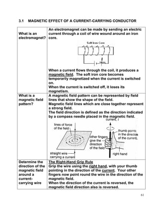
An electromagnet can be made by sending an electric
What is an current through a coil of wire wound around an iron
electromagnet? core.
When a current flows through the coil, it produces a
magnetic field. The soft iron core becomes
temporarily magnetized when the current is switched
on.
When the current is switched off, it loses its
magnetism.
What is a A magnetic field pattern can be represented by field
magnetic field lines that show the shape of the field.
pattern? Magnetic field lines which are close together represent
a strong field.
The field direction is defined as the direction indicated
by a compass needle placed in the magnetic field.
Determine the The Right-Hand Grip Rule
direction of the Grip the wire using the right hand, with your thumb
magnetic field pointing in the direction of the current. Your other
around a fingers now point round the wire in the direction of the
current- magnetic field.
carrying wire When the direction of the current is reversed, the
magnetic field direction also is reversed.
61
2. Activity 1
Aim Draw the magnetic field pattern due to a current in a 1.straight wire,
2. coil 3. solenoid
Determine the direction of the magnetic field.
Procedure
1. Use small plotting compasses and place them on the
cardboard to determine the direction of the magnetic field.
2. Observe and sketch the pattern produced.
3. Reverse the current supply connections to see its effect on
the compass needle.
4. Remove the compasses and springkle iron filings onto the
cardboards and tap the sheets gently with a pencil. Sketch
your observation.
Straight Wire
62
3. Coil
Solenoid
Note:
The right hand grip rule for a
solenoid:
The thumb points towards north
pole of the magnetic field while the
other fingers indicate the direction
of the current in the solenoid.
63
4. State the
factors that
affect the
strength of the
electromagnet.
Describe application of Electromagnet
Electric Bell
• When the bell push is
pressed, a current flows in
the coils of the
electromagnet, causing it to
be magnetized.
• The magnetized
electromagnet attracts the
soft-iron armature, causing
the hammer to strike the
gong.
• The movement of the
armature breaks the contact
and causes the
electromagnet to lose it
magnetism.
• The light spring pulls the • The cycle is repeated so long as the
armature back, remaking the bell push is pressed and continuous
contact and completing the ringing occurs.
circuit again.
•
Magnetic Relay
• A solenoid switch worked by
an electromagnet. It is used
in a circuit which controls the
operation of another circuit,
especially if the current is
large in the second circuit.
• Circuit 1 requires only a
small current.
• When the switch is closed, • causing the soft-iron core to be
current flows in the coil,
64
5. • The movement of the iron magnetized and attracts the amarture
armature closes the contacts • The advantage of using a relay is that
in the second circuit. Circuit a small current (circuit 1) can be
2 is now switched on. used to switch on and off a circuit
• Circuit 2 may have a large with a large current (circuit 2).
current flowing through it to • This is useful for two reasons:
operate powerful motors or (b)circuit 1 may contain a component
very bright lights. such as a light detecting resistor
(LDR), which uses small currents.
(c) Only the circuit with a large
current needs to be connected
with thick wire.
Telephone Ear-piece
• The varying current from the
microphone flows through
the coils of an electromagnet
in the earpiece.
• This pulls the iron diaphragm
towards the electromagnet
by a distance which depends As a result, the diaphragm moves in
on the current. and out and produces sound waves that
are replicas of those that entered the
microphone.
Circuit Breaker
• Acts as an automatic switch
that breaks open a circuit
when the current becomes
too large.
• In a household circuit, the
current may become
excessive when there is a
short circuit or an overload.
• The strength of the magnetic • This results in the spring pulling
field of the electromagnet apart the contacts. The circuit is
increases suddenly. broken and the current flow stops
• The soft iron armature is immediately.
pulled towards the • After repairs have been made, the
electromagnet. reset button is pushed to switch on
the supply again.
65
6. 3.2 THE FORCE ON A CURRENT-CARRYING CONDUCTOR IN A
MAGNETIC FIELD
Describe • An electric current produces a magnetic field around it.
what • When a wire carries an electric current through another
happens to magnetic field, a force is exerted on the wire.
current- • The magnetic force on a current-carrying conductor is in a
carrying magnetic field is due to the combination of the magnetic
conductor field due to the current in the conductor and the external
in a magnetic field to produce a resultant magnetic field.
magnetic
field • The direction of the
magnetic force, F, acting
on the wire can be
determined by using
Fleming’s left-hand rule.
What is If the forefinger, second
Fleming’s finger and the thumb of the
Left – left hand are extended at
Hand Rule right angles to each other,
with the forefinger in the
direction of the magnetic
field, the second finger in
the direction of the current,
then the thumb will point
the direction of the force, F
or motion.
66
7. To investigate the force on a current-carrying conductor in a magnetic
field.
Procedure
1. Switch on the current and observe what happens to the short
copper wire.
2. Reverse the connections of the voltage supply. Observe what
happens to the copper wire.
3. Reverse the magnetic field and repeat step 2 and 3.
4. Align the magnetic field so that it is parallel with in the short
copper wire.
Indicated the flow of current using arrows. Show the direction of
magnetic field and indicate the direction where the short copper
wire will move. Prove the direction of the force using the
Fleming’s left-hand rule.
Observation
step 1 step 2 step 3
Step 4 The direction of magnetic field is parallel
to the direction of current.
The short wire stays at rest.
67
8. Conclusion • When a current-carrying conductor is in a magnetic field of a
permanent magnet, the interaction between the two magnetic
fields produce a force on the conductor.
• The direction of the magnetic field, the current and the force
acting on a conductor is perpendicular to each other.
Describe • The magnadur magnets produce a uniform, parallel
how a magnetic field.
current- • The current-carrying vertical wire produces a circular
carrying magnetic field around itself.
conductor • The two fields interact to produce a resultant magnetic
in a field known as a catapult field.
magnetic • Upward, the two fields are in the same direction and
field they produce a stronger combined field.
experiences • Downward, the two fields act in opposite directions
a force. and the combined field is weaker.
• The wire carrying a current thus experiences a
resultant force in the direction from the stronger to the
weaker field, i.e from upward to downward.
68
9. Explain the factors The magnitude of the force on a current-
that affect the carrying conductor in a magnetic field depends
magnitude of the on:
force on a current- 1. the size of the current in the conductor
carrying conductor in 2. the strength of the magnetic field
a magnetic field.
Draw a pattern of resultant magnetic field or catapult field for a current-
carrying coil in a magnetic field.
69
10. Show the direction of the resultant force, F.
What will happen to the coil?
The coil will rotate clockwise.
Describe Commutator: reverse the
how a direction of current in the coil
direct every half rotation so that the
current coil continues to turn in same
motor direction
works
Carbon Brush: to contact with
the commutator so the current
from the battery enters the coil.
Spring: push the brush so it will
always contact with the
commutator.
70
11. 1. When current flows through the
horizontal coil, magnetic field is
produced around it.
Show The interaction between the magnetic
the field of the current and the magnetic field
direction of the permanent magnet produces a
of the catapult field and 2 turning force. The
two direction of the force is determined by
forces Fleming’s left-hand rule. The two forces
acted on produce a couple which rotates the coil.
the coil.
2.When the coil gets to the upright
position, the contact between the carbon
brushes with the commutator is broken.
There is no turning force on it because
no current flows in the coil. But the coil
continues to rotate because of its inertia.
3.When the coil in a horizontal position
again, the sides of the coil changes
position. The commutator reverses the
direction of the current in the coil to
ensure that the forces on the coil turn the
coil in one direction only. So the coil is
still rotating in the same direction.
4. The above processes are repeated and
the motor continues to rotate.
Factors
which Factors Speed of rotation of the
affect motor
the 1. Increasing the size of the Increases
speed of current
rotation 2. Increasing the strength of Increases
of the the magnetic field
motor 3. increasing the number of Increases
turns
4. Increasing the area of the Increases
coil
71
12. 3.3 ELECTROMAGNETIC INDUCTION
Describe Electromagnetic induction is the production of an
electromagnet electric current by a changing magnetic field.
induction
The induced current is produced only when there is
relative motion between the conductor / coil and the
magnetic field lines.
How induced The relative motion of a conductor across a magnetic
current is field can be produced by:
produced? (a) moving a straight wire quickly across a magnetic
field between two flat magnets.
(b)Moving a permanent magnet towards one end of a
solenoid.
Each time the straight wire cuts across the magnetic
field, or the permanent magnet moves towards the
solenoid, a current is induced in the coil and a
deflection is observed in the sensitive galvanometer.
This current is called induced current. The
electromotive force that is produced is called the
induced e.m.f.
72
13. A. Electromagnetic Induction in a straight wire.
Procedure:
1. Hold the copper rod
stationary between the poles
of the magnet. Observe the
reading of the galvanometer.
2. Move the rod quickly in
Direction 1. Observe the
deflection of the
galvanometer.
3. Repeat step 2 for the other
directions.
• If a galvanometer shows a deflection, it means there is an induced
current produced
• Current is induced in a straight conductor when it moves and cuts
the magnetic field lines.
• The motion of the copper rod must be perpendicular to the direction
of the magnetic field lines so that an induced current will be
produced.
B. Electromagnetic Induction in a solenoid.
1. Push the bar 2. Hold the bar magnet 3. Now pull the bar
magnet into the stationary in the magnet out of the
solenoid. Observe solenoid. Note the solenoid. Observe
the deflection of the reading of the the deflection of the
galvanometer. galvanometer. galvanometer.
• The galvanometer showed a positive reading when the bar magnet
and solenoid were coming closer to each other. This shows that a
current is produced in the solenoid in certain direction.
73
14. • The galvanometer showed a negative reading when the magnet and
solenoid were moving further away from each other. This shows that
a current is produced in the solenoid in the opposite directions.
• A current is induced in a solenoid when there is relative motion
between the solenoid and a magnet.
Conclusion
Current is induced in a straight conductor when it moves and cuts the
magnetic field lines.
Current is induced in a solenoid when there is relative motion between
the solenoid and a magnet.
Indicate the Fleming’s right-hand rule:
direction of A wire PQ is moved
the induced vertically downwards in a
current in a magnetic field. Applying
straight wire Fleming’s right-hand rule,
the induced current will
flow from P to Q.
If the thumb and the first two
fingers on the right hand are
held at right angles to each
other with the first finger
pointing in the direction of
the magnetic field and the
thumb in the direction of the
motion, then the second
finger points in the direction
of the induced current.
Indicate the Lenz’s Law:
direction of The direction of the induced current in a solenoid is
the induced such that its magnetic effect always oppose the change
current in a producing it.
solenoid.
74
15. Magnet is
moved
towards the
solenoid
Magnet is
moved away
from the
solenoid
Lenz’s Law
for solenoid Relative motion between Polarity at the end of the
magnet and solenoid solenoid facing the magnet
Toward each other Same polarity as the magnet
Away from each other Opposite polarity as the
magnet
Principle of
Conservation Lenz’s law is an example of the Principle of
of Energy Conservation of Energy. When the magnet or solenoid
is moved against the opposing force, work is done.
Therefore mechanical energy is converted to electrical
energy.
75
16. Explain Faraday’s Law:
factors that The size of the induced e.m.f is directly proportional to
affect the the rate at which the conductor cuts through the
magnitude of magnetic field lines.
the induced
current. The size of the induced e.m.f. and thus the induced
current and be increased by:
1. moving the magnet or the solenoid at a higher speed
2. increasing the number of turns on the solenoid
3. increasing the strength of the magnetic field through
the use of a stronger magnet.
Show the correct direction of the induced current when the magnet is
moved in the direction shown.
76
17. What is the direction of the induced
current? Determine the poles at P and Q.
Describe Current Generator
applications of • Current generator functions by converting
electromagnetic mechanical energy to electrical energy.
induction • Current generator works based on electromagnetic
induction and uses the Fleming’s Right hand rule.
• Current generator is divided into: direct current
generator and alternate current generator.
Direct Current
Generator
• Commutator: reverses the connections of the coil
with the external circuit after every half cycle, so
that the current in the outside circuit always flows
in the same direction.
77
18. Describe how does a direct current generator work. Show the direction
of movement of the coil AB and CD. Mark the direction of the induced
current in the coil and the galvanometer.
• Coil AB moves …………., coil CD • The sides AB and CD are
moves……….. moving ……………….to the
• When the coil rotates, its sides magnetic field and thus do not
cut across the magnetic field ………..the magnetic field lines.
lines and induced current flows • No …………. …………..is
in the coil from ………………. produced at the instant.
• The galvanometer will deflect to • The galvanometer returns to
…………… …………mark.
• As the coil continues to rotate, • The sides AB and CD are
current will again be induced in moving ……………….to the
the coil but its direction in now magnetic field and thus do not
opposite to that in figure 1 which ………..the magnetic field lines.
is from ….. to ….. and from …… • No …………. …………..is
to …… produced at the instant.
• However, the direction of the • The galvanometer returns to
current through the external …………mark.
circuit remains the same, so the • The process is ……………..
galvanometer deflects to the
…………
78
19. The induced
current varies from
a maximum to
zero, it flows in
one direction only.
Hence, the induced
current is called a
direct current.
Alternating
Current
Generator
• The two ends of the coil are connected to two slip
rings which rotate with the coil.
• Each slip ring is always in contact with the same
carbon brush.
Describe how does an alternating current generator work. Show the
direction of movement of the coil AB and CD. Mark the direction of the
induced current in the coil and the galvanometer.
79
20. • Coil AB moves …………., coil CD
moves……….. • The sides AB and CD are
• When the coil rotates, its sides cut moving ……………….to the
across the magnetic field lines and magnetic field and thus do
induced current flows in the coil not ………..the magnetic field
from ……to …….. and from …… to lines.
…… (using Fleming’s right hand • No …………. …………..is
rule) produced at the instant.
• In the external circuits, current • The galvanometer returns to
flows from …….. to ……. …………mark.
• After the vertical position, the
• The sides AB and CD are
current increases until it attains the
moving ……………….to the
maximum value when the coil is in
magnetic field and thus do
a horizontal position.
not ………..the magnetic field
• Coil CD moves ……………, coil AB
lines.
moves ………….
• No …………. …………..is
• The direction of the induced
produced at the instant.
current is from ….. to ….. and from
• The galvanometer returns to
…… to ……
…………mark.
• The direction of the current • The process is ……………..
through the external circuit is from
80
21. the brush …… to …… which is
reversed.
• The output current generated is an alternating current because the
current changes direction in the external circuit each time the coil
passes the vertical position.
• Assume the current flows from P to Q is positive and the current
flows from Q to P is negative.
• The current changes I magnitude and direction after every half
rotation.
81
22. Compare direct current and alternating current.
1. A direct current is a current that 1. An alternating current is a
flows in one direction only in a current which flows to and fro in
circuit. two opposite directions in a
2. The magnitude of a direct circuit. It changes its direction
current may be: periodically.
(a) constant
(b) changes with time
A direct current can flow through a An alternating current can flow
resistor but cannot flow through a through both a resistor and a
capacitor. capacitor.
Both the direct current and alternating current have a heating effect on
the filament of a bulb and can light up the bulb.
82
23. • The current increases from zero
to a maximum value of + Io (at
A), and back to zero at B. It then
reverses direction and
increases to - Io at C and back to
zero again.
Io = peak current,
Vo = peak voltage
• The time taken for a complete
cycle from O to D is called one
period, T.
• Frequency of the current is f
where f = 1/T
• In Malaysia, the frequency of the
a.c supply is 50 Hz.
Hence, the period of the a.c is :
T = 1/50 = 0.02 seconds.
Figure shows an alternating
current with a magnitude that
changes with time.
(a) What is the peak
current?
(b) What is the period of the
a.c. current?
(c) What is the frequency of
the a.c current?
83
24. 8.4 TRANSFORMERS
What is a A transformer is an electrical device which increases or
transformer? decreases an alternating voltage based on the principle
of electromagnetic induction.
Describe the
structure of a
simple
transformer
• A transformer consists of two coils of wire wound
round separately on a laminated soft-iron core.
• The coil connected to the input voltage is called the
primary coil. The coil connected to the output
voltage is called the secondary coil.
• The purpose of the common iron core is to provide a
magnetic field linkage in the secondary coil.
Describe the • A transformer works on the principle of
operating electromagnetic induction.
principle of a • When a.c voltage, Vp, is applied to the primary coil of
simple transformer, an alternating current flows through the
transformer coil. The soft-iron core is magnetized in one way and
then the other.
• This means that the magnetic flux linkage in the
secondary coil is constantly changing.
• An alternating e.m.f is induced across it to produce
an a.c voltage, Vs in the secondary coil and a.c
current flows through the second coil.
• The frequency of the secondary voltage Vs is the
same as that of the primary voltage, Vp.
• The magnitude of the secondary voltage, Vs, depends
on the ratio of the number of turns of the primary and
secondary coils.
84
25. Why does the • A current is induced in the secondary coil only when
transformer there is a changing magnetic flux due to a changing
not work with primary current. (changes direction and magnitude)
a d.c power • A d.c. power supply gives a constant current in the
supply? primary circuit
• A constant direct current whose magnitude and
direction is constant does not create a changing
magnetic flux in the secondary coil.
• Therefore electromagnetic induction does not take
place.
State the • According to Faraday’s law:
relationship Voltage ∝ number of turns in coils
between
number of V∝N Vp Vs
turns in coils V = kN ∴ =
with voltage Np Ns
in a V
=k
transformer, N
(Vp, Np, Vs Vp = input (primary) voltage
and Ns) Vs = output (secondary) voltage
Np = number of turns in the primary coils
Ns = number of turns in the secondary coils
Compare and Step-up transformer
contrast a If Ns is greater than Np, then Vs is greater than Vp
step-up
transformer Step-down transformer
and a step- If Ns is lower than Np, then Vs is lower than Vp
down
transformer
85
26. Step-up transformer Step-down transformer
Ns > Np Ns < Np
Vs > Vp Vs < Vp
What is the • A transformer transfers electrical power from the
relationship primary circuit to the secondary circuit.
between • The primary circuit of a transformer receives power at
output power a certain voltage from the a.c power supply. The
and input transformer delivers this power at another voltage to
power of an an electrical device connected to the secondary
ideal circuit.
transformer?
• In an ideal transformer, there is no energy loss during
the process of transforming the voltage.
[Power supplied to = [Power used in the
the primary coil] secondary coil]
Input power = Output power
VpIp = VsIs
Describe the • In a real transformer, some energy is lost in the
energy loses transformer especially in the form of heat.
in a • The output power is less than the input power.
transformer • Therefore the efficiency of the transformer is less
than 100%.
86
27. • Efficiency = output power X 100%
Efficiency of Input power
a transformer
• The power loss is due to
(a) heating of coils
(b) eddy currents in the iron core
(c) magnetization and demagnetization of core
(d) leakage of magnetic flux.
Causes of energy loss in Ways to improve the efficiency of
transformers a transformer
Resistance of the coils Use thick copper wires to make
• all coils will have resistance the coils
• heat is produced when current The resistance will reduce as the
flows through them wire is thicker.
Eddy currents in the core Use laminated cores to reduce
• the changing magnetic field will eddy currents
also induces current in the
iron core
• this induced current is called
eddy current
• cause heat to be produced in
the iron cores.
Magnetization and
demagnetization of the core Use cores made from soft-iron as
• the alternating current flowing soft-iron core can be easily
through the transformer magnetized and demagnetized.
continually magnetizes and
demagnetizes the core
• work has to be done to change
the magnitude and direction of
the magnetic field in the core
which contributes to energy
loss
87
28. Leakage of magnetic field Wind the secondary coil on top of
• electrical energy is lost when a the primary coil
fraction of the magnetic field
produced by the primary coil
does not link with the
secondary coil.
Solve problems involving transformers
1. A transformer is required to step
down the mains voltage of 240 V
provide a 12 V supply for an electric
toy. If the primary coil is wound with
1 000 turns of wire, calculate the
number of turns required for the
secondary coil.
2. A step up transformer has 10 000
turns on its secondary coil and 100
turns on its primary coil. An
alternating current of 5.0 A flows in
the primary coil when it is connected
to a 12 V a.c supply. Calculate:
(a) the input power to the
transformer
(b) the e.m.f induced across the
secondary coil.
(c) What is the maximum current that
could flow in a circuit connected
to the secondary coil if the
transformer is 100% efficient.
88
29. 8.5 GENERATION AND TRANSMISSION OF ELECTRICITY
Electricity is generated in power stations, transmitted (sent) through
long-distance cables, and then distributed to consumers.
List • Renewable energy sources : an energy resource
sources of that is continually replaced and will not run out.
energy • Non-renewable sources: an energy resource that
used to cannot be replaced once it has been used.
generated
electricity Renewable energy Non-renewable energy
Describe • Electricity is produces using generators
the various • A generator has a huge magnet that is turned by
ways of a turbine.
generating • As the magnet turns inside a coil of wire,
electricity electricity is produced by electromagnetic
induction.
• Many sources of energy are used to turn these
turbines.
Coal-fired 1. Coal is burned and the heat energy is used to
power produce high pressure steam.
station 2. The steam produced is used to drive the
generators to produce electricity.
3. The energy changes: chemical energy to heat
energy to kinetic energy to electric energy
Gas-fired 1. The burning of natural gas produces high
power pressure steam that is used to drive turbines.
station 2. The energy changes: chemical energy to heat
energy to kinetic energy to electric energy
89
30. Hydro- 1. A huge dam is built across rivers to contain
electric water.
power 2. When the water in the dam is allowed to flow
station down to a lower level, the kinetic energy of the
moving water is used to drive water turbines,
which in turn drive the generators to produce
electricity.
3. The energy changes: potential energy to kinetic
energy to electric energy
Nuclear 1. Energy from nuclear fission (splitting of
power uranium 235 atoms) is used to produce high
station pressure steam to drive turbines
2. The energy changes: nuclear energy to heat
energy to kinetic energy to electric energy
Biomass 1. Biomass includes rotting plants and agricultural
wastes such as oil palm kernels and household
sewage that are used to produce methane gas
and alcohol.
2. Heat energy from the burning of biomass is
used to generate electricity
Solar 1. Solar energy originates from the sun
2. Solar cells use sun energy to generate small
electrical energy to power calculators.
3. Solar panels use sun energy to generate heat
energy to heat water at home.
Wind 1. High speed wind can be used to turn the blades
generator of large windmills which will in turn drive
generators to produce electricity.
90
31. Describe the • Electrical energy is transmitted from power station
transmission to the consumer using long transmission cables or
of electricity power lines.
• Electrical energy is transmitted at a high voltage and
use alternating current.
• A step-up transformer which increases the voltage
to as high as 110,000 or 132, 000 V.
• Step-down transformers are used to decrease the
voltage before being delivered to the consumers.
• The long tick cables used as transmission lines are
made of copper or aluminium
Describe the • The heating effect due to the resistance of the cables
energy loss causes loss of electrical energy as heat energy.
in electricity • When a current flows in a cable, the power loss, P
transmission 2
through heating is P = I R where R is the
cables
resistance of the cable.
deduce the
advantage of • The power loss can be reduced by
high voltage (a) reducing the resistance of the cables
transmission (b) reducing the current in the cables
• In order to reduce resistance of the cables, a thick
cable is used eg copper or aluminium. But thick
cables are very expensive to install and will be too
heavy to be supported securely.
• The loss of power in the transmissions of electricity is
reduced by reducing the current in the cables.
• The power to be transmitted by the cables is
P = VI where I = current in the cables,
V = voltage of the cables.
P
• The current in the cables: I=
V
• This means that the current in the cables is inversely
proportional to the voltage of the cables for a certain
value of power transmission.
• When power is transmitted at lower voltage, the
current in the cables is large.
• The greater the current in the cables, the greater the
power loss.
91
32. Activity 1: Solve problems involving electricity transmission
1. Find the power loss in a
transmission cable when
20 kW is transmitted
through a cable of 1.5 Ω
(i) at a voltage of 200 V
(ii) at a voltage of 10 kV.
What is the effect of the
energy losses in case (i)
and (ii)?
2. Electric power is
transmitted from a power
station to a town by a
transmission cables with a
total resistance of 50 Ω. If
the power station
generates 8 MW of power,
calculate the power loss in
the cables if power is
transmitted
(a) at 80 kV
(b) at 400 kV
What is the • National Grid Network is a network system of high
National voltages cables which connects all the power stations
Grid in the country to the consumers.
Network • Electricity is generated at 25 kV at the power station. It
is then stepped up in a transformer to 132 kV before it
is sent to the grid network.
• The purpose of increasing the voltage to 132 kV is to
lower the current flowing through the grid, and this
reducing power loss during transmission.
• The high voltage in the grid is subsequently reduced by
sub station transformers for distribution to local users.
• Heavy industries will be supplied with power at 33 kV.
Light industries will be supplied with power at 11 kV.
92
33. Offices will be supplied with power at 415 V while
domestic users will be supplied with power at 240 V.
• Cost of generation of electricity is reduced because
State the high voltage transmission reduces the current flowing
importance through the cables and hence reduces power loss in
of the the cables.
National • Power stations in areas where the demand is low can
Grid supply electricity to areas where the demand is high.
Network • If a particular station breaks down or is shut down for
maintenance work, the other stations can supply
electrical energy to the affected area.
• The grid network also enables less efficient stations to
be shut down at off-peak period, thereby reducing the
overall cost of generation and transmission.
• Power stations can be located outside city limits so
that air and environmental pollution can be reduced.
Transmission issues
Alternating • An alternating current is used in the
current, a.c transmission of electrical energy at a high
voltage because its voltage can be easily
increased or decreased with transformers.
• A transformer cannot function with a direct
current.
High voltage or Electrical power is transmitted at a high voltage
low voltage? so that
• The current in the cables is smaller
• The loss of power due to heating of the cables
is minimized.
93
34. Overhead or • High voltage cables are the cheapest way of
underground? sending power over long distances.
• However, to prevent sparking, the only effective
way of insulating the cables is to keep huge air
spaces around them
• The cable have to be suspended from pylons.
Cost of cables • Copper cables have low resistance but are of
high cost
• Aluminium cables are usually used as they are
light, have low resistance and cost less.
Charge leakage • To prevent charge leakage, the aluminium
between the cables are supported by high metal pylons.
cables and the • The metal support of the pylon is earthed so
earth that it is safe to workers and the public who
come into contact with them.
Danger of being • The pylons carry lightning conductors that are
struck by properly fixed into the ground
lightning • The cables are properly fixed with porcelain
support so that the cables do not touch the
pylons.
Danger of being • Lights and special markers must be attached to
struck by light the pylons.
aircraft
Theft • Stricter laws should be enforced to deter
thieves from stealing the aluminium cables.
Explain the • Non-renewable sources of energy such as crude oil,
importance coal and natural gases are fast depleting. Alternatives
of must be found to replace such sources to ensure
renewable continuous supply of power in the future.
energy • Renewable energy sources are those which originate
from the sun or the earth and will last as long as the
Solar System itself.
• From the sun: solar panels, solar cells, biomass, wind
and wave energy, hydroelectric power
• From the earth: geothermal energy, energy from the
tides.
• Renewable sources of energy do not pollute the
environment.
94
35. • For renewable sources of energy to be widely used,
many hurdles must be overcomed, especially those
related to the economical production and distribution
of power generated from such sources.
Explain the effects on the environment caused by the use of various
sources to generate electricity.
Energy Advantages Disadvantages
resource
Hydro • Renewable energy • Building of dams can
• Water is freely available upset the balance of the
in large quantities ecosystem
• Clean and does not • Not suitable in areas
pollute the environment where natural disasters
• Water stored in dams such as earthquakes
can be used to irrigate may occur
farms • Not suitable in flat and
• Dams can be used to dry regions.
control floods
• Dams can be promoted
as recreational centre
Oil and • At present it is still • Non-renewable energy
natural available in large • Discharges harmful
gas quantities gases that can pollute
• Can be transported to the environment
the location where it is • High cost
to be used
Solar • Renewable energy • Requires very large
• Freely available space to collect
• Clean and no pollution sufficient energy
• Lower efficiency in the
generation of electricity
• Intensity of sunlight is
dependent of seasonal
changes, climate and
latitude of the region.
• High cost
95
36. Coal • Plenty of resources • Non-renewable energy
available for up to 200 • Discharges harmful
years gases that can pollute
• Can be transported to the environment
the location where it is
to be used
Nuclear • A small amount uranium • High cost of building
can release a large • Waste in the form of
quantity of energy used fuel rods which are
• Minimum discharge of very hot and highly
carbon dioxide radioactive
• Reactor in nuclear • Hot water discharged
power stations can be causes thermal
used to produce useful pollution to the
radioisotopes to be environment
used in industry, • Risk of accidents which
medicine and may lead to the leakage
agriculture of large amounts of
radioactive substances
to the environment.
Biomass • Renewable energy • Requires large storage
• Reduces problem of space far from human
disposal of organic population if the
waste biomass is animal dung
or sewage.
Wind • Renewable energy • Requires many
• Clean and does not windmills which cover a
pollute environment larger area
• Generates high level of
noise
96