SlideShare una empresa de Scribd logo
1 de 28
List of Apparatus in Hydraulic Lab:
1) Pipe friction apparatus
2) Losses in pipe Bending and Fitting apparatus
3) Dead weight Tester
4) Dead weight Tester
5) Orifice Discharge apparatus
6) Pelton Wheel Turbine
7) Kaplan Turbine apparatus
8) Francis Turbine
9) Drag Coefficient apparatus
10) Series and parallel pump
11) Hydraulic Bench
12) Centrifugal pump Test bench
13) Hybrology apparatus
14) Energy Losses pipe Bends
15) Water Hammer apparatus
White board
Chair
Window
Layout
Experiment # 1
Definition of layout:
Master plan or blueprint of a printed or published work that lays out the
arrangement of its different graphic elements It establishes the overall appearance, relative
importance, and relationships between the graphic elements to achieve a smooth flow of
information.
Objectives of layout:
 Effective use of men, machines and materials.
 Minimize of the materials handling cost.
 Better supervision and control.
 Waste control easily
Types of layout:
 Product layout
 Process layout
 Fixed layout
 Combination layout
Product layout:
If all the process, equipments and machines are arranged according to the
sequence of operation of the layout is called product layout. In this type of layout only one type
of the produce in a operation area.
Process layout:
In this layout machines Men and equipments are not arrange order to the
sequence but arrange ordering to the type or nature of the operation. This layout is commonly
suitable for non repetitive jobs.
Fixed layout:
In this type of layout the major compoment remain at a fixed notation but
the other material, tools, machines , men power and other supporting equipment are bring to this
fixed notation.
Combination layout:
When two or more type of layout are combine is called combination layout.
e.g combination of product layout and process layout.
Energy losses in Bends
Theory:
When fluid flow through a typical pipe fitting such as an elbow or abed an enlargement or
contraction in cross section, or through a valve energy losses occur. These energy losses which
are termed as minor losses are primarily due to the change in the direction of the fluid and the
change in cross section of the flow path typically occurs in valves and fitting. Thus the head loss
is also proportional to the velocity head of the fluid . Experimental values for energy losses are
usually report in terms of a loss coefficient ,K, as follows:
HL = Kv2/2g
In which
K = Loss coefficient
V = Average velocity of a flow in the small pipe (m/s)
g = Acceleration due to the gravity (9.81 m/s2 )
Characteristic of flow through pipe fitting and valve:
Elbows: 45o elbow and 90o elbow:
The value of loss coefficient K is depended on the ratio of the bend radius R to the pipe inner
diameter D. As this ratio increase the value of K will fall and vice versa.
Figure 1 Elbow Fitting
Short Bend:
Losses of head in bends are caused by the combined effects of separation wall friction and the
twin eddy secondary flow. For large radius bends the head loss is predominant by the last two
effects whereas for short bends it is more dominated by separation and secondary flow .Value of
K is dependent on the shape of passage and Reynolds number.
Sudden Enlargement:
As a fluid flow from a smaller pipe into a larger pipe through a sudden enlargement its velocity
decreases causing turbulence that generates an energy loss. Assuming that the piezometric
pressure on the face of the enlargement to be equal to that in the emerging pressure jet and that
momentum flux is conserved the total head loss is given by
∆𝐻 =
( 𝑣1 − 𝑣2)2
2𝑔
In this case the loss coefficient K is related to the upstream velocity v1 so that
𝐾 =
( 𝑣1 − 𝑣2)2
2𝑔
𝑣12
2𝑔
= (1 −
𝑣2
𝑣1
)
2
= (1 −
𝐴1
𝐴2
)
2
This shows that K increases from zero when A1/A2=1 to 1when A1/A2=0
Figure 2 Long and short bend
Sudden Contraction:
As the streamlines approach the contraction they assume a curved path and the total stream
continues to neck down for some distance beyond the contraction. This section where the
minimum flow area occurs is called the vena contract. The turbulence caused by the contraction
and the subsequent expansion generates energy loss which is given by
Δ𝐻 =
( 𝑣𝑐 − 𝑣2)2
2𝑔
In this case K is
𝐾 = (
𝑣𝑐
𝑣2
− 1)
2
= (
𝐴2
𝐴𝑐
− 1)
2
Gate Valve:
Gate valve is one of several types of valves that are used to control the amount of flow. The
valve of loss coefficient K of a gate valve is dependent on the position of the valve. Fluids flow
through the fully open gate valve in straight line paths. For the fluid flow through partially
opened gate valve resistance to flow will be greater and thus produces a larger valve of K.
Figure 3 sudden enlargement
Figure 4 Sudden contraction
Equipment:
1. Base Frame with Rear Wall
2. Hose connection water inlet
3. Hose connection water outlet
4. Pipe elbow
5. Rounded pipe elbow
6. Tight Radius pipe bend
7. Large Radius pipe bend
8. Reducer
9. Enlarge
10. Spherical valve
11. PVC Hose with plug in connector
Figure 5 Energy losses n bends
Experiment#2
Objective:
To measuring the losses through gate valve related to flow rate.
Apparatus:
 Hydraulic Bench
 Energy losses in bend Equipment
Procedure:
 Place apparatus on the bench connect inlet pipe to bench supply and outlet pipe into
volumetric tank.
 With the bench valve fully closed and the discharge valve fully opened start up the pump
supply from hydraulic bench.
 Slowly open the bench valve until it is fully opened.
 When the flow in the pipe is steady and there is no trapped bubble start to close the bench
valve to reduce the flow to the maximum measurable flow rate.
 Slowly close the gate valve to 4.5 turns position and measure and record the differential
pressure reading across the valve.
 Repeat the differential pressure measurement with different decreasing flow rates. The
rates can be adjusted by utilizing the bench flow control valve.
 Plot graph differential Piezometer head ‘H’ against velocity head for the gate valve and
determine the loss coefficient.
 The experiment can be repeated with different gate valve opening
Observations:
Volume
V
(liter)
Time
T (s)
Flow
rate
(m3/s)
Manometer reading (mm H2O)
1 2 3 4 5 6 7 8 9 10 11 12
5 21.75 2.299E-
04
318 369 303 299 318 251 235 203 20 70 247 219
5 23.89 2.093E-
04
307 354 294 290 307 249 234 206 48 90 245 220
5 29.49 1.69E-
04
289 325 280 277 290 245 234 212 87 120 241 222
5 39.72 1.259E-
04
264 284 259 258 264 240 234 223 148 166 235 225
Flow
rate
(m3/s)
Velocity
in small
bore
pipe
(m/s)
𝒗 =
𝟒𝑸
𝝅𝒅
Velocity
Head
mH2O
V2/2g
Differential Piezometer Head ∆𝒉(mH2O)
90o
Elbow
Sudden
Enlargement
Sudden
Contraction
45o
Elbow
Short
Bend
2.299E-
04
1.0127 5.23E-02 0.051 0.004 0.067 0.032 0.028
2.093E-
04
0.9220 4.33E-02 0.047 0.004 0.058 0.028 0.025
1.695E-
04
0.7499 2.84E-02 0.036 0.003 0..45 0.022 0.019
1.259E-
04
0.554 1.57E-02 0.020 0.001 0.024 0.011 0.010
Sample Calculation:
Flow rate, Q= (Volume/Time)
= 5/21.75*1000
= 2.299 E-04 m3/s
Velocity in small bore pipe
𝑉 =
4𝑄
𝜋𝑑
𝑉 =
4∗2.299
3.14∗0.0172
V= 1.0127m/s
Velocity Head
=V2/2g
=1.10272/2*9.81
= 0.0523 mH2O
Differential piezometer Head ∆ℎ for 90o elbow = (H2-H1)/1000
= (369-318)/1000
= 0.051 m H2O
Differential piezometer Head ∆ℎ for sudden enlargement = (H3-H4)/1000
= (303-299)/1000
= 0.004 m H2O
Differential piezometer Head ∆ℎ for sudden contraction = (H5-H6)/1000
= (318-251)/1000
= 0.067 m H2O
Differential piezometer Head ∆ℎ for 45o elbow = (H7-H8)/1000
= (205-203)/1000
= 0.032 m H2O
Differential piezometer Head ∆ℎ for short bend= (H11-H12)/1000
= (247-219)/1000
= 0.028 m H2O
0
0.01
0.02
0.03
0.04
0.05
0.06
0.00E+00 5.00E-05 1.00E-04 1.50E-04 2.00E-04 2.50E-04
DifferentialpiezometerHead(mH2O)
Velocity Head (m/H2O)
90o Elbow
90o Elbow
0
0.0005
0.001
0.0015
0.002
0.0025
0.003
0.0035
0.004
0.0045
0.00E+00 5.00E-05 1.00E-04 1.50E-04 2.00E-04 2.50E-04
DifferentialpiezometerHead(mH2O)
Velocity Head (m/H2O)
Sudden
Enlargement
Sudden
Enlargement
Experiment # 3
Objective:
To measuring the losses through gate valve related to flow rate and calculating loss coefficient
related to velocity head.
Apparatus:
 Hydraulic Bench
 Energy losses in bend Equipment
Procedure:
 Place apparatus on the bench connect inlet pipe to bench supply and outlet pipe into
volumetric tank.
 With the bench valve fully closed and the discharge valve fully opened start up the pump
supply from hydraulic bench.
 Slowly open the bench valve until it is fully opened.
 When the flow in the pipe is steady and there is no trapped bubble start to close the bench
valve to reduce the flow to the maximum measurable flow rate.
 Slowly close the gate valve to 4.5 turns position and measure and record the differential
pressure reading across the valve.
 Repeat the differential pressure measurement with different decreasing flow rates. The
rates can be adjusted by utilizing the bench flow control valve.
 Plot graph differential Piezometer head ‘H’ against velocity head for the gate valve and
determine the loss coefficient.
 The experiment can be repeated with different gate valve opening
Observations:
Volume V
(liter)
Time
(s)
Flow rate Q (m3/s) Differential Pressure
across Valve (psi)
5 13.78 3.63E-04 20
5 17.00 2.94E-04 15
5 20.15 2.84E-04 10
Flow rate Q
(m3/s)
Velocity in
Small Bore pipe
v (m/s)
Velocity Head
(mH2O)
Differential
Pressure across
Valve (mH2O)
Valve Position
3.63E-04 1.59 0.130 14.06 41/2 Turns
2.94E-04 1.29 0.086 10.55 41/2 Turns
2.48E-04 1.093 0.061 7.03 41/2 Turns
Calculation of the head loss for experiment
For flow Rate :
= Volume/time
=5/21.75*1000
=2.299E-04m3/s
Velocity in small bore pipe
=4Q/πD2
=4*2.299/π*0.0172
=1.0127m/s
Velocity Head:
=V2/2g
=1.01272/2*9.81
=0.0523m/s
Differential piezometer Head ∆ℎ for 90o elbow = (H2-H1)/1000
= (369-318)/1000
= 0.051 m H2O
Differential piezometer Head ∆ℎ for sudden enlargement = (H3-H4)/1000
= (303-299)/1000
= 0.004 m H2O
Differential piezometer Head ∆ℎ for sudden contraction = (H5-H6)/1000
= (318-251)/1000
= 0.067 m H2O
Differential piezometer Head ∆ℎ for 45o elbow = (H7-H8)/1000
= (205-203)/1000
= 0.032 m H2O
Differential piezometer Head ∆ℎ for short bend= (H11-H12)/1000
= (247-219)/1000
= 0.028 m H2O
0
2
4
6
8
10
12
14
16
0 0.02 0.04 0.06 0.08 0.1 0.12 0.14
DifferentialPressureacrossValve
(mH2O)
Velocity Head (mH2o)
DifferentialPressureacross Valve vs
Velocity Head
Pelton Wheel turbine:
Theory:
PeltonWheel Turbine:
The Pelton wheel is an impulse-type water turbine. The Pelton wheel extracts energy from the
impulse of moving water, as opposed to water's dead weight like the traditional overshot water
wheel. Many variations of impulse turbines existed prior to Pelton's design, but they were less
efficient than Pelton's design. Water leaving those wheels typically still had high speed, carrying
away much of the dynamic energy brought to the wheels. Pelton's paddle geometry was designed
so that when the rim ran at half the speed of the water jet, the water left the wheel with very little
speed; thus his design extracted almost all of the water's impulse energy which allowed for a
very efficient turbine.
Working of Pelton Wheel:
Nozzles direct forceful, high-speed streams of water against a series of spoon-shaped buckets,
also known as impulse blades, which are mounted around the outer rim of a drive wheel also
called a runner. As the water jet hits the blades, the direction of water velocity is changed to
follow the contours of the blades. The impulse energy of the water jet exerts torque on the
bucket-and-wheel system, spinning the wheel; the water jet does a and exits at the outer sides of
the bucket, decelerated to a low velocity. In the process, the water jet's momentum is transferred
to the wheel and hence to a turbine. Thus, "impulse" energy does work on the turbine. Maximum
power and efficiency are achieved when the velocity of the water jet is twice the velocity of the
rotating buckets. A very small percentage of the water jet's original kinetic energy will remain in
the water, which causes the bucket to be emptied at the same rate it is filled and thereby allows
the high-pressure input flow to continue uninterrupted and without waste of energy. Typically
two buckets are mounted side-by-side on the wheel, with the water jet split into two equal
streams; this balances the side-load forces on the wheel and helps to ensure smooth, efficient
transfer of momentum from the water jet to the turbine wheel. Because water is nearly
incompressible, almost all of the available energy is extracted in the first stage of the hydraulic
turbine. Therefore, Pelton wheels have only one turbine stage, unlike gas turbines that operate
with compressible fluid.
Figure 6 Pelton Turbine
Applications
Pelton wheels are the preferred turbine for hydro-power where the available water source has
relatively high hydraulic head at low flow rates. Pelton wheels are made in all sizes. There exist
multi-ton Pelton wheels mounted on vertical oil pad bearings in hydroelectric plants. The largest
units - the Bourdon Hydroelectric Power Station at the Grande Decency Dam complex in
Switzerland - are over 400 megawatts. The smallest Pelton wheels are only a few inches across,
and can be used to tap power from mountain streams having flows of a few gallons per minute.
Some of these systems use household plumbing fixtures for water delivery. These small units are
recommended for use with 30 meters or more of head, in order to generate significant power
levels. Depending on water flow and design, Pelton wheels operate best with heads from 15–
1,800 meters although there is no theoretical limit.
Experiment # 04
Objective:
To determine the mechanical power of pelton wheel turbine.
Apparatus:
 Hydraulic Bench
 Pelton Wheel Turbine
Procedure:
 Connect the apparatus with the hydraulic bench.
 Switch on the hydraulic bench pump.
 Open the valve slowly so that water begin to flow through the turbine.
 Adjust the flow rate in turbine by valve of the hydraulic bench.
 Number of the nozzles can be varied using valves V1 V2 V3 V4.
 Load the turbine by turning the adjustment breaking device.
 Note down the speed of turbine in rpm with the help of tachometer.
 Now the torque can be calculated by
T=Fb*r
r: radius of pulley = 25mm
 The mechanical power produced bythe turbine can be calculated by
P=2πnT/60
n: speed of the turbine in rpm
Observation:
Sr. # n (rpm) Net force F
(N)
Torque T
(Nm)
Power
(watt)
1 900 20 0.5 48.22
2 940 22 0.53 50.66
3 955 24 0.59 53.55
Sample Calculation:
F1=50 N
F2= 30 N
Fb=F1-F2
Fb=50-30
=20 N
T=Fb*r
T= (20)(0.025)
T= 0.5 Nm
PM=2πnT/60
PM=2(3.14)(900)(0.5)/60
PM=48.22 watt
Mechanical power of Turbine (Kaplan turbine)
Theory:
Hydraulic machines:
Hydraulic machines are defined as those machines convert either hydraulic energy into
mechanical energy or mechanical energy to hydraulic energy.
Turbine:
Turbines are defined as hydraulic machines which convert hydraulic energy into mechanical
energy. Hydraulic turbines are different types according to specification and Francis turbine is
one of the types of hydraulic turbine.
Reaction Turbine:
A reaction turbine is a type of steam turbine that works on the principle that the rotor spins, as
the name suggests, from a reaction force rather than an impact or impulse force. In a reaction
turbine there are no nozzles to direct the steam like in the impulse turbine. Instead, the blades
that project radially from the outer edge of the rotor are shaped and mounted so that the shape
between the blades, created by the cross-section, creates the shape of a nozzle. These blades are
mounted on the revolving part of the rotor and are called the moving blades.
Figure 7 Reaction Turbine
Radially outward flow reaction turbine:
This reaction turbine consist a cylindrical disc mounted on a shaft and provided with vanes
around the perimeter. At inlet the water flows into the wheel at the centre and then glides through
radially provided fixed guide vanes and then flow over the moving vanes. The water as it flows
along the moving vanes will exert a thrust and hence a torque on the wheel there by rotating the
wheel. The water leaves the moving vanes at the outlet edge. The wheel is enclosed by a water
tight casing. The water is thehen taken to draft tube.
Radially inward flow reaction turbine:
The constitutional details of this turbine are similar to the outward flow turbine but for the fact
that the guide vanes surround the moving vanes. This is preferred to the outward flow turbine as
the turbine does not develop racing. The centrifugal force on the inward moving body of water
decreases the relative velocity and thus the speed of the turbine can be controlled easily.
The main component of a reactionturbine:
 Spiral casing
 Guide mechanism
 Turbine runner
 Draft tube
Spiral casing:
The casing of reaction turbine is designed in such a way that its cross sectional area goes on
reducing uniformly around the circumference. The cross sectional area is maximum at the
entrance and minimum at the tip. Due to this, the casing will be of spiral shape. That is why it is
called spiral casing or scroll casing. The water from a pipeline is distributed around the guide
ring in a casing. The material of the casing depends upon the head of water. If head is up to 30
meter then concrete should be used. If head is up to 100 meter then welded rolled steel plate
should be used. If it is more than 100 meter then cast steel should be used for casing.
Guide vanes:
All the guide vanes can rotate about their respective pivots. Pivots are connected to the guided
ring or regulating ring. This ring is connected to the regulating shaft by means of two regulating
rods. Guide vanes may be closed or opened by rotating the regulating shaft, thus allowing
required quantity of water to flow. The regulating shaft is operated by a governor whose function
is to govern the turbine. Governor function is to keep the speed constant at varying loads. Guide
vanes are generally made of cast steel. Guide vanes allow the water to enter the runner without
shock. Guide vanes keep relative velocity at inlet of the runner, tangential to the vane angle and
thus results in entering of water without shock.
Allow the water to flow over them without forming eddies. Allow the required quantity of water
to enter the turbine. This is done by adjusting the vanes.
Runner blades:
Runner blades are said to be heart of a reaction turbine. It is the shape of the runner blades which
uses the pressure energy of water to run turbine. Their design plays a major role in deciding the
efficiency of a turbine. In modern turbines these blades can pitch about their axis, thus can vary
the pressure force acting on them according to the load and available pressure.
Draft tube:
Draft tube connects the runner exit to the tail race. Its cross-section area increases along its
length, as the water coming out of runner blades is at considerably low pressure, so its expanding
cross-section area help it to recover the pressure as it flows towards tail race.
Figure 8 Component of reaction turbine
Experiment#5
Objective:
To determine the mechanical power produced by the turbine.
Apparatus:
 Hydraulic Bench
 Kaplan Turbine
Procedure:
 Connect the apparatus with the hydraulic bench.
 Switch on the hydraulic bench pump.
 Open the valve slowly so that water begin to flow through the turbine.
 Adjust the flow rate in turbine by valve of the hydraulic bench.
 Number of the nozzles can be varied using valves V1 V2 V3 V4.
 Load the turbine by turning the adjustment breaking device.
 Note down the speed of turbine in rpm with the help of tachometer.
 Now the torque can be calculated by
T=Fb*r
r: radius of pulley = 25mm
 The mechanical power produced bythe turbine can be calculated by
P=2πnT/60
n: speed of the turbine in rpm
Observation:
Sr. # n (rpm) Net force F
(N)
Torque T
(Nm)
Power
(watt)
1 900 20 0.5 48.22
2 940 22 0.53 50.66
3 955 24 0.59 53.55
Sample Calculation:
F1=50 N
F2= 30 N
Fb=F1-F2
Fb=50-30
=20 N
T=Fb*r
T= (20)(0.025)
T= 0.5 Nm
PM=2πnT/60
PM=2(3.14)(900)(0.5)/60
PM=48.22 watt
Mechanical power of Francis Turbine
Theory:
Hydraulic machines:
Hydraulic machines are defined as those machines convert either hydraulic energy into
mechanical energy or mechanical energy to hydraulic energy.
Turbine:
Turbines are defined as hydraulic machines which convert hydraulic energy into mechanical
energy. Hydraulic turbines are different types according to specification and Francis turbine is
one of the types of hydraulic turbine.
Reaction Turbine:
A reaction turbine is a type of steam turbine that works on the principle that the rotor spins, as
the name suggests, from a reaction force rather than an impact or impulse force. In a reaction
turbine there are no nozzles to direct the steam like in the impulse turbine. Instead, the blades
that project radically from the outer edge of the rotor are shaped and mounted so that the shape
between the blades, created by the cross-section, creates the shape of a nozzle. These blades are
mounted on the revolving part of the rotor and are called the moving blades.
Francis Turbine:
The inward flow reaction turbine having radial discharge at outlet is known as Francis turbine. In
the modern Francis turbine the water enters the runner of the turbine in the radial direction and
leaves in the axial direction at the outlet of the runner. Thus the modern Francis turbine is a
mixed flow type turbine.
Figure 9 Francis turbine
1 Accelerated flow enters runner
2 From outside and flow radically through inside. The peripheral velocities at inlet and exit are
different. The moving blades are curved backwards. Water exits axially from runner
3 The flow rate and hence the power can be regulated by adjustable fixed blades.
The main component of a reaction turbine:
• Penstock
• Casing
• Guide mechanism
• Runner
• Draft tube
Penstock:
It is a long pipe at the outlet of which a nozzle is fitted. The water from reservoir flows through
the penstock. The nozzle increases the kinetic energy of water flowing the penstock.
Casing:
The casing of reaction turbine is designed in such a way that its cross sectional area goes on
reducing uniformly around the circumference. The cross sectional area is maximum at the
entrance and minimum at the tip. Due to this, the casing will be of spiral shape. That is why it is
called spiral casing or scroll casing. The water from a pipeline is distributed around the guide
ring in a casing. The material of the casing depends upon the head of water. If head is up to 30
meter then concrete should be used. If head is up to 100 meter then welded rolled steel plate
should be used. If it is more than 100 meter then cast steel should be used for casing.
Guide:
All the guide vanes can rotate about their respective pivots. Pivots are connected to the guided
ring or regulating ring. This ring is connected to the regulating shaft by means of two regulating
rods. Guide vanes may be closed or opened by rotating the regulating shaft, thus allowing
required quantity of water to flow. The regulating shaft is operated by a governor whose function
is to govern the turbine. Governor function is to keep the speed constant at varying loads. Guide
vanes are generally made of cast steel. Guide vanes allow the water to enter the runner without
shock. Guide vanes keep relative velocity at inlet of the runner, tangential to the vane angle and
thus results in entering of water without shock.
Allow the water to flow over them without forming eddies. Allow the required quantity of water
to enter the turbine. This is done by adjusting the vanes.
Runner:
Runner blades are said to be heart of a reaction turbine. It is the shape of the runner blades which
uses the pressure energy of water to run turbine. Their design plays a major role in deciding the
efficiency of a turbine. In modern turbines these blades can pitch about their axis, thus can vary
the pressure force acting on them according to the load and available pressure.
Draft tube:
Draft tube connects the runner exit to the tail race. Its cross-section area increases along its
length, as the water coming out of runner blades is at considerably low pressure, so its expanding
cross-section area help it to recover the pressure as it flows towards tail race.
Experiment#6
Objective:
To determine the mechanical power produced by the turbine.
Procedure:
 Position experimentation setup on hydraulic bench such that the outlet from the draft tube
can guide the water into the duct of hydraulic bench.
 Make hose connection between hydraulic bench and connection of franis turbine using
quick release connectors
 Use the head wheel to fully release brake unit of turbine. This relieves the load on the
spring balances and the belt is no longer pulled against the pulley.
 Close the main hydraulic bench’s cock and switch on pump slowly open cock as for as it
will go.
 Release lever for vane adjustment by turning it and expel air from the draft tube by
slowly opening and closing the vanes.
 The angle of impact of the water on the runner vanes is stipulated by the position of the
vanes. The above angle determines the speed and also power of turbine.
 Vanes adjustment is released by turning the lever.
 Now open the water supply from the hydraulic bench.
 Load the turbine by turning adjustment breaking device.
 Note down the speed of turbine in rpm with the help of tachometer. Note down the
breaking power F.
Fb=F1-F2
 Now the torque can be calculated by
T=Fb*r
r=25mm=radius of pulley
 The mechanical power produced by the turbine can be calculated by
PM=2πnT/60
n=speed of the turbine in rpm
Sr.# n
(rpm)
Force F1
(N)
Force F2
(N)
Net Force
Fb (N)
Torque T
(Nm)
Power PM
(watt)
1 900 50 30 20 0.5 47.1
2 950 55 33 22 0.55 51.6
3 975 59 35 24 0.6 56.2
Sample Calculation:
F1=50 N
F2= 30 N
Fb=F1-F2
Fb=50-30
=20 N
T=Fb*r
T= (20)(0.025)
T= 0.5 Nm
PM=2πnT/60
PM=2(3.14)(900)(0.5)/60
PM=47.1 watt

Más contenido relacionado

La actualidad más candente

La actualidad más candente (20)

Chap 03
Chap 03Chap 03
Chap 03
 
Characteristics of single pump and pumps in series and parallel use of indust...
Characteristics of single pump and pumps in series and parallel use of indust...Characteristics of single pump and pumps in series and parallel use of indust...
Characteristics of single pump and pumps in series and parallel use of indust...
 
Flow through pipe
Flow through pipeFlow through pipe
Flow through pipe
 
Flow through orifice meter
Flow through orifice meterFlow through orifice meter
Flow through orifice meter
 
Fluid Mechanics Chapter 4. Differential relations for a fluid flow
Fluid Mechanics Chapter 4. Differential relations for a fluid flowFluid Mechanics Chapter 4. Differential relations for a fluid flow
Fluid Mechanics Chapter 4. Differential relations for a fluid flow
 
Fluid Mechanic Lab - Venturi Meter
Fluid Mechanic Lab - Venturi MeterFluid Mechanic Lab - Venturi Meter
Fluid Mechanic Lab - Venturi Meter
 
Heat exchanger lab 2
Heat exchanger lab 2Heat exchanger lab 2
Heat exchanger lab 2
 
Centrifugal pump | Fluid Laboratory
Centrifugal pump | Fluid LaboratoryCentrifugal pump | Fluid Laboratory
Centrifugal pump | Fluid Laboratory
 
120218 chapter 8 momentum analysis of flow
120218 chapter 8 momentum analysis of flow120218 chapter 8 momentum analysis of flow
120218 chapter 8 momentum analysis of flow
 
Dimensional analysis Similarity laws Model laws
Dimensional analysis Similarity laws Model laws Dimensional analysis Similarity laws Model laws
Dimensional analysis Similarity laws Model laws
 
Presentation on notches and weirs
Presentation on notches and weirsPresentation on notches and weirs
Presentation on notches and weirs
 
Unit 5 Fluid Mechanics
Unit 5 Fluid MechanicsUnit 5 Fluid Mechanics
Unit 5 Fluid Mechanics
 
Fluid Mechanic Lab - Reynold's Number Experiment
Fluid Mechanic Lab - Reynold's Number ExperimentFluid Mechanic Lab - Reynold's Number Experiment
Fluid Mechanic Lab - Reynold's Number Experiment
 
Fluid Mechanics Chapter 2. Fluid Statics
Fluid Mechanics Chapter 2. Fluid StaticsFluid Mechanics Chapter 2. Fluid Statics
Fluid Mechanics Chapter 2. Fluid Statics
 
Fluid mechanics lab manual
Fluid mechanics lab manualFluid mechanics lab manual
Fluid mechanics lab manual
 
Flow in pipes
Flow in pipesFlow in pipes
Flow in pipes
 
Deflection of curved beam |Strength of Material Laboratory
Deflection of curved beam |Strength of Material LaboratoryDeflection of curved beam |Strength of Material Laboratory
Deflection of curved beam |Strength of Material Laboratory
 
Steam turbine
Steam turbineSteam turbine
Steam turbine
 
Flow through pipes ppt
Flow through pipes pptFlow through pipes ppt
Flow through pipes ppt
 
friction loss along a pipe
friction loss along a pipefriction loss along a pipe
friction loss along a pipe
 

Similar a Energy losses in Bends, loss coefficient related to velocity head.Pelton Wheel turbine.Mechanical power of Turbine (Kaplan turbine).. Mechanical power of Francis Turbine.

Flow measurement basics
Flow measurement basicsFlow measurement basics
Flow measurement basics
Salman1011
 
Variable Headmeter
Variable HeadmeterVariable Headmeter
Variable Headmeter
Shivang258
 

Similar a Energy losses in Bends, loss coefficient related to velocity head.Pelton Wheel turbine.Mechanical power of Turbine (Kaplan turbine).. Mechanical power of Francis Turbine. (20)

Minor losses elbow
Minor losses elbowMinor losses elbow
Minor losses elbow
 
Fluid_Mechanics_Lab_IVSem (1).pdf
Fluid_Mechanics_Lab_IVSem (1).pdfFluid_Mechanics_Lab_IVSem (1).pdf
Fluid_Mechanics_Lab_IVSem (1).pdf
 
Minor losses valve
Minor losses  valveMinor losses  valve
Minor losses valve
 
Minor losses elbow
Minor losses elbowMinor losses elbow
Minor losses elbow
 
Minor losses valve
Minor losses valveMinor losses valve
Minor losses valve
 
Fm lab manual
Fm lab manual Fm lab manual
Fm lab manual
 
Flow measurement basics
Flow measurement basicsFlow measurement basics
Flow measurement basics
 
Design Of Flow Meters
Design Of Flow MetersDesign Of Flow Meters
Design Of Flow Meters
 
Calibration of venturi and orifice meters
Calibration of venturi and orifice metersCalibration of venturi and orifice meters
Calibration of venturi and orifice meters
 
pipe friction for turbulent
pipe friction for turbulentpipe friction for turbulent
pipe friction for turbulent
 
pipe friction for turbulent
pipe friction for turbulentpipe friction for turbulent
pipe friction for turbulent
 
Water hammer in pumped sewer mains
Water hammer in pumped sewer mainsWater hammer in pumped sewer mains
Water hammer in pumped sewer mains
 
pipe friction for laminar
pipe friction for laminarpipe friction for laminar
pipe friction for laminar
 
pipe friction for laminar
pipe friction for laminarpipe friction for laminar
pipe friction for laminar
 
Variable Headmeter
Variable HeadmeterVariable Headmeter
Variable Headmeter
 
B_B1_G3_CP_HMAFP.pptx
B_B1_G3_CP_HMAFP.pptxB_B1_G3_CP_HMAFP.pptx
B_B1_G3_CP_HMAFP.pptx
 
Presentation - energy lose
Presentation - energy losePresentation - energy lose
Presentation - energy lose
 
Pump pipeline
Pump pipelinePump pipeline
Pump pipeline
 
exp.9 flow meter demonstration
exp.9 flow meter demonstrationexp.9 flow meter demonstration
exp.9 flow meter demonstration
 
Effect on Efficiency of Two-phase Flow Distribution in a Parallel Flow Heat E...
Effect on Efficiency of Two-phase Flow Distribution in a Parallel Flow Heat E...Effect on Efficiency of Two-phase Flow Distribution in a Parallel Flow Heat E...
Effect on Efficiency of Two-phase Flow Distribution in a Parallel Flow Heat E...
 

Más de Salman Jailani

Más de Salman Jailani (20)

Fan and Blowers
 Fan and Blowers Fan and Blowers
Fan and Blowers
 
Insulation and Refractories
 Insulation and Refractories Insulation and Refractories
Insulation and Refractories
 
Furnaces
 Furnaces  Furnaces
Furnaces
 
Compressed air_system ( chapter complete )
 Compressed air_system  ( chapter complete ) Compressed air_system  ( chapter complete )
Compressed air_system ( chapter complete )
 
cooling tower, Factors Affecting Cooling Tower Performance,Efficient System O...
cooling tower, Factors Affecting Cooling Tower Performance,Efficient System O...cooling tower, Factors Affecting Cooling Tower Performance,Efficient System O...
cooling tower, Factors Affecting Cooling Tower Performance,Efficient System O...
 
Boilers and its types systems and boilers water treatment
Boilers and its types systems and boilers water treatment Boilers and its types systems and boilers water treatment
Boilers and its types systems and boilers water treatment
 
Global environment concerns
Global environment concernsGlobal environment concerns
Global environment concerns
 
Energy Resources and Utilization
Energy Resources  and Utilization Energy Resources  and Utilization
Energy Resources and Utilization
 
Energy management
Energy managementEnergy management
Energy management
 
Energy management & audit
Energy management & auditEnergy management & audit
Energy management & audit
 
Steam leakage
Steam leakageSteam leakage
Steam leakage
 
Lab layout
Lab layoutLab layout
Lab layout
 
Lab lay out data
Lab lay out dataLab lay out data
Lab lay out data
 
Machining Technology-2 MT-474 (Practical)
Machining Technology-2 MT-474 (Practical)Machining Technology-2 MT-474 (Practical)
Machining Technology-2 MT-474 (Practical)
 
Lab report title
Lab report title Lab report title
Lab report title
 
Refrigeration and Heat Pump Systems
Refrigeration and Heat Pump SystemsRefrigeration and Heat Pump Systems
Refrigeration and Heat Pump Systems
 
Safety Inspections and Sample Safety Inspection.Health and safety training D...
Safety Inspections and Sample Safety Inspection.Health  and safety training D...Safety Inspections and Sample Safety Inspection.Health  and safety training D...
Safety Inspections and Sample Safety Inspection.Health and safety training D...
 
Cnc turning
Cnc turning Cnc turning
Cnc turning
 
Cnc milling turning
Cnc milling turning Cnc milling turning
Cnc milling turning
 
CNC machining centers
CNC machining centersCNC machining centers
CNC machining centers
 

Último

Cara Menggugurkan Sperma Yang Masuk Rahim Biyar Tidak Hamil
Cara Menggugurkan Sperma Yang Masuk Rahim Biyar Tidak HamilCara Menggugurkan Sperma Yang Masuk Rahim Biyar Tidak Hamil
Cara Menggugurkan Sperma Yang Masuk Rahim Biyar Tidak Hamil
Cara Menggugurkan Kandungan 087776558899
 
Hospital management system project report.pdf
Hospital management system project report.pdfHospital management system project report.pdf
Hospital management system project report.pdf
Kamal Acharya
 

Último (20)

Unit 4_Part 1 CSE2001 Exception Handling and Function Template and Class Temp...
Unit 4_Part 1 CSE2001 Exception Handling and Function Template and Class Temp...Unit 4_Part 1 CSE2001 Exception Handling and Function Template and Class Temp...
Unit 4_Part 1 CSE2001 Exception Handling and Function Template and Class Temp...
 
HOA1&2 - Module 3 - PREHISTORCI ARCHITECTURE OF KERALA.pptx
HOA1&2 - Module 3 - PREHISTORCI ARCHITECTURE OF KERALA.pptxHOA1&2 - Module 3 - PREHISTORCI ARCHITECTURE OF KERALA.pptx
HOA1&2 - Module 3 - PREHISTORCI ARCHITECTURE OF KERALA.pptx
 
Double Revolving field theory-how the rotor develops torque
Double Revolving field theory-how the rotor develops torqueDouble Revolving field theory-how the rotor develops torque
Double Revolving field theory-how the rotor develops torque
 
Thermal Engineering Unit - I & II . ppt
Thermal Engineering  Unit - I & II . pptThermal Engineering  Unit - I & II . ppt
Thermal Engineering Unit - I & II . ppt
 
AIRCANVAS[1].pdf mini project for btech students
AIRCANVAS[1].pdf mini project for btech studentsAIRCANVAS[1].pdf mini project for btech students
AIRCANVAS[1].pdf mini project for btech students
 
Block diagram reduction techniques in control systems.ppt
Block diagram reduction techniques in control systems.pptBlock diagram reduction techniques in control systems.ppt
Block diagram reduction techniques in control systems.ppt
 
Employee leave management system project.
Employee leave management system project.Employee leave management system project.
Employee leave management system project.
 
S1S2 B.Arch MGU - HOA1&2 Module 3 -Temple Architecture of Kerala.pptx
S1S2 B.Arch MGU - HOA1&2 Module 3 -Temple Architecture of Kerala.pptxS1S2 B.Arch MGU - HOA1&2 Module 3 -Temple Architecture of Kerala.pptx
S1S2 B.Arch MGU - HOA1&2 Module 3 -Temple Architecture of Kerala.pptx
 
Cara Menggugurkan Sperma Yang Masuk Rahim Biyar Tidak Hamil
Cara Menggugurkan Sperma Yang Masuk Rahim Biyar Tidak HamilCara Menggugurkan Sperma Yang Masuk Rahim Biyar Tidak Hamil
Cara Menggugurkan Sperma Yang Masuk Rahim Biyar Tidak Hamil
 
Computer Networks Basics of Network Devices
Computer Networks  Basics of Network DevicesComputer Networks  Basics of Network Devices
Computer Networks Basics of Network Devices
 
GEAR TRAIN- BASIC CONCEPTS AND WORKING PRINCIPLE
GEAR TRAIN- BASIC CONCEPTS AND WORKING PRINCIPLEGEAR TRAIN- BASIC CONCEPTS AND WORKING PRINCIPLE
GEAR TRAIN- BASIC CONCEPTS AND WORKING PRINCIPLE
 
Hospital management system project report.pdf
Hospital management system project report.pdfHospital management system project report.pdf
Hospital management system project report.pdf
 
PE 459 LECTURE 2- natural gas basic concepts and properties
PE 459 LECTURE 2- natural gas basic concepts and propertiesPE 459 LECTURE 2- natural gas basic concepts and properties
PE 459 LECTURE 2- natural gas basic concepts and properties
 
COST-EFFETIVE and Energy Efficient BUILDINGS ptx
COST-EFFETIVE  and Energy Efficient BUILDINGS ptxCOST-EFFETIVE  and Energy Efficient BUILDINGS ptx
COST-EFFETIVE and Energy Efficient BUILDINGS ptx
 
DC MACHINE-Motoring and generation, Armature circuit equation
DC MACHINE-Motoring and generation, Armature circuit equationDC MACHINE-Motoring and generation, Armature circuit equation
DC MACHINE-Motoring and generation, Armature circuit equation
 
A CASE STUDY ON CERAMIC INDUSTRY OF BANGLADESH.pptx
A CASE STUDY ON CERAMIC INDUSTRY OF BANGLADESH.pptxA CASE STUDY ON CERAMIC INDUSTRY OF BANGLADESH.pptx
A CASE STUDY ON CERAMIC INDUSTRY OF BANGLADESH.pptx
 
Wadi Rum luxhotel lodge Analysis case study.pptx
Wadi Rum luxhotel lodge Analysis case study.pptxWadi Rum luxhotel lodge Analysis case study.pptx
Wadi Rum luxhotel lodge Analysis case study.pptx
 
Hostel management system project report..pdf
Hostel management system project report..pdfHostel management system project report..pdf
Hostel management system project report..pdf
 
Navigating Complexity: The Role of Trusted Partners and VIAS3D in Dassault Sy...
Navigating Complexity: The Role of Trusted Partners and VIAS3D in Dassault Sy...Navigating Complexity: The Role of Trusted Partners and VIAS3D in Dassault Sy...
Navigating Complexity: The Role of Trusted Partners and VIAS3D in Dassault Sy...
 
Online electricity billing project report..pdf
Online electricity billing project report..pdfOnline electricity billing project report..pdf
Online electricity billing project report..pdf
 

Energy losses in Bends, loss coefficient related to velocity head.Pelton Wheel turbine.Mechanical power of Turbine (Kaplan turbine).. Mechanical power of Francis Turbine.

  • 1.
  • 2. List of Apparatus in Hydraulic Lab: 1) Pipe friction apparatus 2) Losses in pipe Bending and Fitting apparatus 3) Dead weight Tester 4) Dead weight Tester 5) Orifice Discharge apparatus 6) Pelton Wheel Turbine 7) Kaplan Turbine apparatus 8) Francis Turbine 9) Drag Coefficient apparatus 10) Series and parallel pump 11) Hydraulic Bench 12) Centrifugal pump Test bench 13) Hybrology apparatus 14) Energy Losses pipe Bends 15) Water Hammer apparatus White board Chair Window
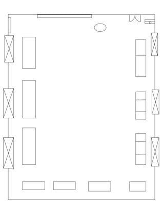
  • 3. Layout Experiment # 1 Definition of layout: Master plan or blueprint of a printed or published work that lays out the arrangement of its different graphic elements It establishes the overall appearance, relative importance, and relationships between the graphic elements to achieve a smooth flow of information. Objectives of layout:  Effective use of men, machines and materials.  Minimize of the materials handling cost.  Better supervision and control.  Waste control easily Types of layout:  Product layout  Process layout  Fixed layout  Combination layout Product layout: If all the process, equipments and machines are arranged according to the sequence of operation of the layout is called product layout. In this type of layout only one type of the produce in a operation area. Process layout: In this layout machines Men and equipments are not arrange order to the sequence but arrange ordering to the type or nature of the operation. This layout is commonly suitable for non repetitive jobs. Fixed layout: In this type of layout the major compoment remain at a fixed notation but the other material, tools, machines , men power and other supporting equipment are bring to this fixed notation. Combination layout: When two or more type of layout are combine is called combination layout. e.g combination of product layout and process layout.
  • 4. Energy losses in Bends Theory: When fluid flow through a typical pipe fitting such as an elbow or abed an enlargement or contraction in cross section, or through a valve energy losses occur. These energy losses which are termed as minor losses are primarily due to the change in the direction of the fluid and the change in cross section of the flow path typically occurs in valves and fitting. Thus the head loss is also proportional to the velocity head of the fluid . Experimental values for energy losses are usually report in terms of a loss coefficient ,K, as follows: HL = Kv2/2g In which K = Loss coefficient V = Average velocity of a flow in the small pipe (m/s) g = Acceleration due to the gravity (9.81 m/s2 ) Characteristic of flow through pipe fitting and valve: Elbows: 45o elbow and 90o elbow: The value of loss coefficient K is depended on the ratio of the bend radius R to the pipe inner diameter D. As this ratio increase the value of K will fall and vice versa. Figure 1 Elbow Fitting
  • 5. Short Bend: Losses of head in bends are caused by the combined effects of separation wall friction and the twin eddy secondary flow. For large radius bends the head loss is predominant by the last two effects whereas for short bends it is more dominated by separation and secondary flow .Value of K is dependent on the shape of passage and Reynolds number. Sudden Enlargement: As a fluid flow from a smaller pipe into a larger pipe through a sudden enlargement its velocity decreases causing turbulence that generates an energy loss. Assuming that the piezometric pressure on the face of the enlargement to be equal to that in the emerging pressure jet and that momentum flux is conserved the total head loss is given by ∆𝐻 = ( 𝑣1 − 𝑣2)2 2𝑔 In this case the loss coefficient K is related to the upstream velocity v1 so that 𝐾 = ( 𝑣1 − 𝑣2)2 2𝑔 𝑣12 2𝑔 = (1 − 𝑣2 𝑣1 ) 2 = (1 − 𝐴1 𝐴2 ) 2 This shows that K increases from zero when A1/A2=1 to 1when A1/A2=0 Figure 2 Long and short bend
  • 6. Sudden Contraction: As the streamlines approach the contraction they assume a curved path and the total stream continues to neck down for some distance beyond the contraction. This section where the minimum flow area occurs is called the vena contract. The turbulence caused by the contraction and the subsequent expansion generates energy loss which is given by Δ𝐻 = ( 𝑣𝑐 − 𝑣2)2 2𝑔 In this case K is 𝐾 = ( 𝑣𝑐 𝑣2 − 1) 2 = ( 𝐴2 𝐴𝑐 − 1) 2 Gate Valve: Gate valve is one of several types of valves that are used to control the amount of flow. The valve of loss coefficient K of a gate valve is dependent on the position of the valve. Fluids flow through the fully open gate valve in straight line paths. For the fluid flow through partially opened gate valve resistance to flow will be greater and thus produces a larger valve of K. Figure 3 sudden enlargement Figure 4 Sudden contraction
  • 7. Equipment: 1. Base Frame with Rear Wall 2. Hose connection water inlet 3. Hose connection water outlet 4. Pipe elbow 5. Rounded pipe elbow 6. Tight Radius pipe bend 7. Large Radius pipe bend 8. Reducer 9. Enlarge 10. Spherical valve 11. PVC Hose with plug in connector Figure 5 Energy losses n bends
  • 8. Experiment#2 Objective: To measuring the losses through gate valve related to flow rate. Apparatus:  Hydraulic Bench  Energy losses in bend Equipment Procedure:  Place apparatus on the bench connect inlet pipe to bench supply and outlet pipe into volumetric tank.  With the bench valve fully closed and the discharge valve fully opened start up the pump supply from hydraulic bench.  Slowly open the bench valve until it is fully opened.  When the flow in the pipe is steady and there is no trapped bubble start to close the bench valve to reduce the flow to the maximum measurable flow rate.  Slowly close the gate valve to 4.5 turns position and measure and record the differential pressure reading across the valve.  Repeat the differential pressure measurement with different decreasing flow rates. The rates can be adjusted by utilizing the bench flow control valve.  Plot graph differential Piezometer head ‘H’ against velocity head for the gate valve and determine the loss coefficient.  The experiment can be repeated with different gate valve opening Observations: Volume V (liter) Time T (s) Flow rate (m3/s) Manometer reading (mm H2O) 1 2 3 4 5 6 7 8 9 10 11 12 5 21.75 2.299E- 04 318 369 303 299 318 251 235 203 20 70 247 219 5 23.89 2.093E- 04 307 354 294 290 307 249 234 206 48 90 245 220 5 29.49 1.69E- 04 289 325 280 277 290 245 234 212 87 120 241 222 5 39.72 1.259E- 04 264 284 259 258 264 240 234 223 148 166 235 225
  • 9. Flow rate (m3/s) Velocity in small bore pipe (m/s) 𝒗 = 𝟒𝑸 𝝅𝒅 Velocity Head mH2O V2/2g Differential Piezometer Head ∆𝒉(mH2O) 90o Elbow Sudden Enlargement Sudden Contraction 45o Elbow Short Bend 2.299E- 04 1.0127 5.23E-02 0.051 0.004 0.067 0.032 0.028 2.093E- 04 0.9220 4.33E-02 0.047 0.004 0.058 0.028 0.025 1.695E- 04 0.7499 2.84E-02 0.036 0.003 0..45 0.022 0.019 1.259E- 04 0.554 1.57E-02 0.020 0.001 0.024 0.011 0.010 Sample Calculation: Flow rate, Q= (Volume/Time) = 5/21.75*1000 = 2.299 E-04 m3/s Velocity in small bore pipe 𝑉 = 4𝑄 𝜋𝑑 𝑉 = 4∗2.299 3.14∗0.0172 V= 1.0127m/s Velocity Head =V2/2g =1.10272/2*9.81 = 0.0523 mH2O Differential piezometer Head ∆ℎ for 90o elbow = (H2-H1)/1000 = (369-318)/1000
  • 10. = 0.051 m H2O Differential piezometer Head ∆ℎ for sudden enlargement = (H3-H4)/1000 = (303-299)/1000 = 0.004 m H2O Differential piezometer Head ∆ℎ for sudden contraction = (H5-H6)/1000 = (318-251)/1000 = 0.067 m H2O Differential piezometer Head ∆ℎ for 45o elbow = (H7-H8)/1000 = (205-203)/1000 = 0.032 m H2O Differential piezometer Head ∆ℎ for short bend= (H11-H12)/1000 = (247-219)/1000 = 0.028 m H2O 0 0.01 0.02 0.03 0.04 0.05 0.06 0.00E+00 5.00E-05 1.00E-04 1.50E-04 2.00E-04 2.50E-04 DifferentialpiezometerHead(mH2O) Velocity Head (m/H2O) 90o Elbow 90o Elbow
  • 11. 0 0.0005 0.001 0.0015 0.002 0.0025 0.003 0.0035 0.004 0.0045 0.00E+00 5.00E-05 1.00E-04 1.50E-04 2.00E-04 2.50E-04 DifferentialpiezometerHead(mH2O) Velocity Head (m/H2O) Sudden Enlargement Sudden Enlargement
  • 12. Experiment # 3 Objective: To measuring the losses through gate valve related to flow rate and calculating loss coefficient related to velocity head. Apparatus:  Hydraulic Bench  Energy losses in bend Equipment Procedure:  Place apparatus on the bench connect inlet pipe to bench supply and outlet pipe into volumetric tank.  With the bench valve fully closed and the discharge valve fully opened start up the pump supply from hydraulic bench.  Slowly open the bench valve until it is fully opened.  When the flow in the pipe is steady and there is no trapped bubble start to close the bench valve to reduce the flow to the maximum measurable flow rate.  Slowly close the gate valve to 4.5 turns position and measure and record the differential pressure reading across the valve.  Repeat the differential pressure measurement with different decreasing flow rates. The rates can be adjusted by utilizing the bench flow control valve.  Plot graph differential Piezometer head ‘H’ against velocity head for the gate valve and determine the loss coefficient.  The experiment can be repeated with different gate valve opening Observations: Volume V (liter) Time (s) Flow rate Q (m3/s) Differential Pressure across Valve (psi) 5 13.78 3.63E-04 20 5 17.00 2.94E-04 15 5 20.15 2.84E-04 10
  • 13. Flow rate Q (m3/s) Velocity in Small Bore pipe v (m/s) Velocity Head (mH2O) Differential Pressure across Valve (mH2O) Valve Position 3.63E-04 1.59 0.130 14.06 41/2 Turns 2.94E-04 1.29 0.086 10.55 41/2 Turns 2.48E-04 1.093 0.061 7.03 41/2 Turns Calculation of the head loss for experiment For flow Rate : = Volume/time =5/21.75*1000 =2.299E-04m3/s Velocity in small bore pipe =4Q/πD2 =4*2.299/π*0.0172 =1.0127m/s Velocity Head: =V2/2g =1.01272/2*9.81 =0.0523m/s Differential piezometer Head ∆ℎ for 90o elbow = (H2-H1)/1000 = (369-318)/1000 = 0.051 m H2O Differential piezometer Head ∆ℎ for sudden enlargement = (H3-H4)/1000 = (303-299)/1000 = 0.004 m H2O Differential piezometer Head ∆ℎ for sudden contraction = (H5-H6)/1000 = (318-251)/1000
  • 14. = 0.067 m H2O Differential piezometer Head ∆ℎ for 45o elbow = (H7-H8)/1000 = (205-203)/1000 = 0.032 m H2O Differential piezometer Head ∆ℎ for short bend= (H11-H12)/1000 = (247-219)/1000 = 0.028 m H2O 0 2 4 6 8 10 12 14 16 0 0.02 0.04 0.06 0.08 0.1 0.12 0.14 DifferentialPressureacrossValve (mH2O) Velocity Head (mH2o) DifferentialPressureacross Valve vs Velocity Head
  • 15. Pelton Wheel turbine: Theory: PeltonWheel Turbine: The Pelton wheel is an impulse-type water turbine. The Pelton wheel extracts energy from the impulse of moving water, as opposed to water's dead weight like the traditional overshot water wheel. Many variations of impulse turbines existed prior to Pelton's design, but they were less efficient than Pelton's design. Water leaving those wheels typically still had high speed, carrying away much of the dynamic energy brought to the wheels. Pelton's paddle geometry was designed so that when the rim ran at half the speed of the water jet, the water left the wheel with very little speed; thus his design extracted almost all of the water's impulse energy which allowed for a very efficient turbine. Working of Pelton Wheel: Nozzles direct forceful, high-speed streams of water against a series of spoon-shaped buckets, also known as impulse blades, which are mounted around the outer rim of a drive wheel also called a runner. As the water jet hits the blades, the direction of water velocity is changed to follow the contours of the blades. The impulse energy of the water jet exerts torque on the bucket-and-wheel system, spinning the wheel; the water jet does a and exits at the outer sides of the bucket, decelerated to a low velocity. In the process, the water jet's momentum is transferred to the wheel and hence to a turbine. Thus, "impulse" energy does work on the turbine. Maximum power and efficiency are achieved when the velocity of the water jet is twice the velocity of the rotating buckets. A very small percentage of the water jet's original kinetic energy will remain in the water, which causes the bucket to be emptied at the same rate it is filled and thereby allows the high-pressure input flow to continue uninterrupted and without waste of energy. Typically two buckets are mounted side-by-side on the wheel, with the water jet split into two equal streams; this balances the side-load forces on the wheel and helps to ensure smooth, efficient transfer of momentum from the water jet to the turbine wheel. Because water is nearly incompressible, almost all of the available energy is extracted in the first stage of the hydraulic turbine. Therefore, Pelton wheels have only one turbine stage, unlike gas turbines that operate with compressible fluid.
  • 16. Figure 6 Pelton Turbine Applications Pelton wheels are the preferred turbine for hydro-power where the available water source has relatively high hydraulic head at low flow rates. Pelton wheels are made in all sizes. There exist multi-ton Pelton wheels mounted on vertical oil pad bearings in hydroelectric plants. The largest units - the Bourdon Hydroelectric Power Station at the Grande Decency Dam complex in Switzerland - are over 400 megawatts. The smallest Pelton wheels are only a few inches across, and can be used to tap power from mountain streams having flows of a few gallons per minute. Some of these systems use household plumbing fixtures for water delivery. These small units are recommended for use with 30 meters or more of head, in order to generate significant power levels. Depending on water flow and design, Pelton wheels operate best with heads from 15– 1,800 meters although there is no theoretical limit.
  • 17. Experiment # 04 Objective: To determine the mechanical power of pelton wheel turbine. Apparatus:  Hydraulic Bench  Pelton Wheel Turbine Procedure:  Connect the apparatus with the hydraulic bench.  Switch on the hydraulic bench pump.  Open the valve slowly so that water begin to flow through the turbine.  Adjust the flow rate in turbine by valve of the hydraulic bench.  Number of the nozzles can be varied using valves V1 V2 V3 V4.  Load the turbine by turning the adjustment breaking device.  Note down the speed of turbine in rpm with the help of tachometer.  Now the torque can be calculated by T=Fb*r r: radius of pulley = 25mm  The mechanical power produced bythe turbine can be calculated by P=2πnT/60 n: speed of the turbine in rpm Observation: Sr. # n (rpm) Net force F (N) Torque T (Nm) Power (watt) 1 900 20 0.5 48.22 2 940 22 0.53 50.66 3 955 24 0.59 53.55
  • 18. Sample Calculation: F1=50 N F2= 30 N Fb=F1-F2 Fb=50-30 =20 N T=Fb*r T= (20)(0.025) T= 0.5 Nm PM=2πnT/60 PM=2(3.14)(900)(0.5)/60 PM=48.22 watt
  • 19. Mechanical power of Turbine (Kaplan turbine) Theory: Hydraulic machines: Hydraulic machines are defined as those machines convert either hydraulic energy into mechanical energy or mechanical energy to hydraulic energy. Turbine: Turbines are defined as hydraulic machines which convert hydraulic energy into mechanical energy. Hydraulic turbines are different types according to specification and Francis turbine is one of the types of hydraulic turbine. Reaction Turbine: A reaction turbine is a type of steam turbine that works on the principle that the rotor spins, as the name suggests, from a reaction force rather than an impact or impulse force. In a reaction turbine there are no nozzles to direct the steam like in the impulse turbine. Instead, the blades that project radially from the outer edge of the rotor are shaped and mounted so that the shape between the blades, created by the cross-section, creates the shape of a nozzle. These blades are mounted on the revolving part of the rotor and are called the moving blades. Figure 7 Reaction Turbine
  • 20. Radially outward flow reaction turbine: This reaction turbine consist a cylindrical disc mounted on a shaft and provided with vanes around the perimeter. At inlet the water flows into the wheel at the centre and then glides through radially provided fixed guide vanes and then flow over the moving vanes. The water as it flows along the moving vanes will exert a thrust and hence a torque on the wheel there by rotating the wheel. The water leaves the moving vanes at the outlet edge. The wheel is enclosed by a water tight casing. The water is thehen taken to draft tube. Radially inward flow reaction turbine: The constitutional details of this turbine are similar to the outward flow turbine but for the fact that the guide vanes surround the moving vanes. This is preferred to the outward flow turbine as the turbine does not develop racing. The centrifugal force on the inward moving body of water decreases the relative velocity and thus the speed of the turbine can be controlled easily. The main component of a reactionturbine:  Spiral casing  Guide mechanism  Turbine runner  Draft tube Spiral casing: The casing of reaction turbine is designed in such a way that its cross sectional area goes on reducing uniformly around the circumference. The cross sectional area is maximum at the entrance and minimum at the tip. Due to this, the casing will be of spiral shape. That is why it is called spiral casing or scroll casing. The water from a pipeline is distributed around the guide ring in a casing. The material of the casing depends upon the head of water. If head is up to 30 meter then concrete should be used. If head is up to 100 meter then welded rolled steel plate should be used. If it is more than 100 meter then cast steel should be used for casing. Guide vanes: All the guide vanes can rotate about their respective pivots. Pivots are connected to the guided ring or regulating ring. This ring is connected to the regulating shaft by means of two regulating rods. Guide vanes may be closed or opened by rotating the regulating shaft, thus allowing required quantity of water to flow. The regulating shaft is operated by a governor whose function is to govern the turbine. Governor function is to keep the speed constant at varying loads. Guide vanes are generally made of cast steel. Guide vanes allow the water to enter the runner without shock. Guide vanes keep relative velocity at inlet of the runner, tangential to the vane angle and thus results in entering of water without shock.
  • 21. Allow the water to flow over them without forming eddies. Allow the required quantity of water to enter the turbine. This is done by adjusting the vanes. Runner blades: Runner blades are said to be heart of a reaction turbine. It is the shape of the runner blades which uses the pressure energy of water to run turbine. Their design plays a major role in deciding the efficiency of a turbine. In modern turbines these blades can pitch about their axis, thus can vary the pressure force acting on them according to the load and available pressure. Draft tube: Draft tube connects the runner exit to the tail race. Its cross-section area increases along its length, as the water coming out of runner blades is at considerably low pressure, so its expanding cross-section area help it to recover the pressure as it flows towards tail race. Figure 8 Component of reaction turbine
  • 22. Experiment#5 Objective: To determine the mechanical power produced by the turbine. Apparatus:  Hydraulic Bench  Kaplan Turbine Procedure:  Connect the apparatus with the hydraulic bench.  Switch on the hydraulic bench pump.  Open the valve slowly so that water begin to flow through the turbine.  Adjust the flow rate in turbine by valve of the hydraulic bench.  Number of the nozzles can be varied using valves V1 V2 V3 V4.  Load the turbine by turning the adjustment breaking device.  Note down the speed of turbine in rpm with the help of tachometer.  Now the torque can be calculated by T=Fb*r r: radius of pulley = 25mm  The mechanical power produced bythe turbine can be calculated by P=2πnT/60 n: speed of the turbine in rpm Observation: Sr. # n (rpm) Net force F (N) Torque T (Nm) Power (watt) 1 900 20 0.5 48.22 2 940 22 0.53 50.66 3 955 24 0.59 53.55
  • 23. Sample Calculation: F1=50 N F2= 30 N Fb=F1-F2 Fb=50-30 =20 N T=Fb*r T= (20)(0.025) T= 0.5 Nm PM=2πnT/60 PM=2(3.14)(900)(0.5)/60 PM=48.22 watt
  • 24. Mechanical power of Francis Turbine Theory: Hydraulic machines: Hydraulic machines are defined as those machines convert either hydraulic energy into mechanical energy or mechanical energy to hydraulic energy. Turbine: Turbines are defined as hydraulic machines which convert hydraulic energy into mechanical energy. Hydraulic turbines are different types according to specification and Francis turbine is one of the types of hydraulic turbine. Reaction Turbine: A reaction turbine is a type of steam turbine that works on the principle that the rotor spins, as the name suggests, from a reaction force rather than an impact or impulse force. In a reaction turbine there are no nozzles to direct the steam like in the impulse turbine. Instead, the blades that project radically from the outer edge of the rotor are shaped and mounted so that the shape between the blades, created by the cross-section, creates the shape of a nozzle. These blades are mounted on the revolving part of the rotor and are called the moving blades. Francis Turbine: The inward flow reaction turbine having radial discharge at outlet is known as Francis turbine. In the modern Francis turbine the water enters the runner of the turbine in the radial direction and leaves in the axial direction at the outlet of the runner. Thus the modern Francis turbine is a mixed flow type turbine.
  • 25. Figure 9 Francis turbine 1 Accelerated flow enters runner 2 From outside and flow radically through inside. The peripheral velocities at inlet and exit are different. The moving blades are curved backwards. Water exits axially from runner 3 The flow rate and hence the power can be regulated by adjustable fixed blades. The main component of a reaction turbine: • Penstock • Casing • Guide mechanism • Runner • Draft tube Penstock: It is a long pipe at the outlet of which a nozzle is fitted. The water from reservoir flows through the penstock. The nozzle increases the kinetic energy of water flowing the penstock. Casing: The casing of reaction turbine is designed in such a way that its cross sectional area goes on reducing uniformly around the circumference. The cross sectional area is maximum at the entrance and minimum at the tip. Due to this, the casing will be of spiral shape. That is why it is called spiral casing or scroll casing. The water from a pipeline is distributed around the guide ring in a casing. The material of the casing depends upon the head of water. If head is up to 30 meter then concrete should be used. If head is up to 100 meter then welded rolled steel plate should be used. If it is more than 100 meter then cast steel should be used for casing. Guide:
  • 26. All the guide vanes can rotate about their respective pivots. Pivots are connected to the guided ring or regulating ring. This ring is connected to the regulating shaft by means of two regulating rods. Guide vanes may be closed or opened by rotating the regulating shaft, thus allowing required quantity of water to flow. The regulating shaft is operated by a governor whose function is to govern the turbine. Governor function is to keep the speed constant at varying loads. Guide vanes are generally made of cast steel. Guide vanes allow the water to enter the runner without shock. Guide vanes keep relative velocity at inlet of the runner, tangential to the vane angle and thus results in entering of water without shock. Allow the water to flow over them without forming eddies. Allow the required quantity of water to enter the turbine. This is done by adjusting the vanes. Runner: Runner blades are said to be heart of a reaction turbine. It is the shape of the runner blades which uses the pressure energy of water to run turbine. Their design plays a major role in deciding the efficiency of a turbine. In modern turbines these blades can pitch about their axis, thus can vary the pressure force acting on them according to the load and available pressure. Draft tube: Draft tube connects the runner exit to the tail race. Its cross-section area increases along its length, as the water coming out of runner blades is at considerably low pressure, so its expanding cross-section area help it to recover the pressure as it flows towards tail race.
  • 27. Experiment#6 Objective: To determine the mechanical power produced by the turbine. Procedure:  Position experimentation setup on hydraulic bench such that the outlet from the draft tube can guide the water into the duct of hydraulic bench.  Make hose connection between hydraulic bench and connection of franis turbine using quick release connectors  Use the head wheel to fully release brake unit of turbine. This relieves the load on the spring balances and the belt is no longer pulled against the pulley.  Close the main hydraulic bench’s cock and switch on pump slowly open cock as for as it will go.  Release lever for vane adjustment by turning it and expel air from the draft tube by slowly opening and closing the vanes.  The angle of impact of the water on the runner vanes is stipulated by the position of the vanes. The above angle determines the speed and also power of turbine.  Vanes adjustment is released by turning the lever.  Now open the water supply from the hydraulic bench.  Load the turbine by turning adjustment breaking device.  Note down the speed of turbine in rpm with the help of tachometer. Note down the breaking power F. Fb=F1-F2  Now the torque can be calculated by T=Fb*r r=25mm=radius of pulley  The mechanical power produced by the turbine can be calculated by PM=2πnT/60 n=speed of the turbine in rpm Sr.# n (rpm) Force F1 (N) Force F2 (N) Net Force Fb (N) Torque T (Nm) Power PM (watt) 1 900 50 30 20 0.5 47.1 2 950 55 33 22 0.55 51.6 3 975 59 35 24 0.6 56.2
  • 28. Sample Calculation: F1=50 N F2= 30 N Fb=F1-F2 Fb=50-30 =20 N T=Fb*r T= (20)(0.025) T= 0.5 Nm PM=2πnT/60 PM=2(3.14)(900)(0.5)/60 PM=47.1 watt