

Recomendados
Más contenido relacionado
La actualidad más candente
La actualidad más candente (20)
Similar a Revit glossary terms
Similar a Revit glossary terms (20)
Más de Sandya Devarajan
Más de Sandya Devarajan (14)
Último
Último (20)
Revit glossary terms
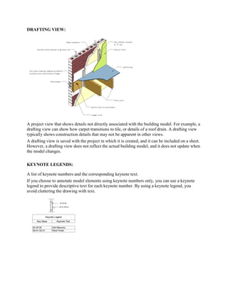
- 1. DRAFTING VIEW: A project view that shows details not directly associated with the building model. For example, a drafting view can show how carpet transitions to tile, or details of a roof drain. A drafting view typically shows construction details that may not be apparent in other views. A drafting view is saved with the project in which it is created, and it can be included on a sheet. However, a drafting view does not reflect the actual building model, and it does not update when the model changes. KEYNOTE LEGENDS: A list of keynote numbers and the corresponding keynote text. If you choose to annotate model elements using keynote numbers only, you can use a keynote legend to provide descriptive text for each keynote number. By using a keynote legend, you avoid cluttering the drawing with text.
- 2. SCOPE BOXES: A user interface mechanism that controls the visibility of datum planes (levels, reference lines, and grids) in views. When you add grids, levels, and reference lines to a project, they may display in more views than desired. For example, when you add grid lines to a plan view, the grid lines display in all plan views of the model. To limit the appearance of datum planes to certain views, use a scope box.
- 3. MATCHLINES: A sketch line that indicates where to split a view for a dependent view, as shown. PROJECT PARAMETERS: User-defined fields that you add to multiple categories of elements, sheets, or views in a project. These parameters are specific to the project and cannot be shared with other projects. For example, you can create a project parameter named Approved By for views. In the properties for each view, you can enter a value for this parameter to indicate who approved the view. You can use project parameters in multi-category or single-category schedules. However, you cannot use project parameters in tags for model elements. SHARED PARAMETERS: User-defined fields that you add to families or projects and then share with other families and projects. They are stored in a file independently of a family file or Revit project; this allows you to access the file from different families or projects. In addition, shared parameters can be used in tags for model elements, and they can display in schedules. GLOBAL PARAMETERS: Global parameters are specific to a single project file, but are not assigned to categories like project parameters. Global parameters can be simple values, values derived from equations, or values taken from the model using other global parameters. TRANSFER PROJECT: Transfer Project Standards' which allows you to transfer settings, system families and much more from one file to another..To transfer project standards. Open both the source and target projects. In the target project, click Manage tab Settings panel (Transfer Project Standards). In the Select Items to Copy dialog, select the source project for Copy from. Select the desired project standards.
- 4. PURGE: Remove unused views, families, and other objects from the project to improve performance and reduce file size. Select or clear check boxes to indicate the objects to purge from the project. The tool does not allow you to purge used objects, or objects that have dependencies. PROJECT BASE: The project base point defines the origin (0,0,0) of the project coordinate system. It also can be used to position a building on a site and for locating the design elements of a building during construction. SURVEY POINT: The survey point represents a known point in the physical world, such as a geodetic survey marker. The survey point is used to correctly orient a building’s geometry in another coordinate system, such as the coordinate system used in a civil engineering application. DESIGN OPTION: An alternative design for a project. Design options allow a team to develop, evaluate, and redesign building components within a single project file. You can develop design options to adapt to changes in product scope, to review other designs, or to show alternatives to a client.
- 5. PHASES: A stage or time period in the construction process of a building project. Typical phases include existing construction, demolition, remodeling, and new construction. Revit Architecture tracks the phase in which views or components are created or demolished, and lets you apply phase-specific filters to views so you can define how the project appears during various stages of work. The following project views show different phases of construction for one project.
- 6. EDIT SELECTION: To help you identify elements and mark them for selection, Revit includes an automatic highlighting feature. When you move the cursor onto or near an element in the drawing area, the outline of the element is highlighted. ... A description of the element displays on the status bar at the bottom of the Revit window. SELECT BY ID: Many of the controls and tools that you use to modify an element in the drawing area are available only when an element is selected. In Revit Architecture, a selected element displays in the selection color, and controls or handles indicate how the element can be manipulated or modified. COPE:
- 7. Coping can be applied to steel members of the model, such as beams and columns. For example, in locations where beams frame into girders, Revit can cope the beam around the girder. ... Click Modify Tab Geometry panel Cope drop-down (Apply Coping). Select the element to which coping is to be applied. SPLIT FACE : The Split Face tool splits the selected face of the element; it does not change the structure of the element. You can use Split Face on any non-family instance. After splitting the face, you can use the Paint tool to apply a different material to this section of face. See Applying a Material to the Face of an Element.
- 8. SPLIT ELEMENT: To divide a single object into multiple objects or sections. In a Revit project, you can split walls, lines, faces, toposurfaces, layers in vertically compound walls, and schedules using various split tools. OVERRIDE GRAPHICS IN VIEW: A 3D view that shows a building model in which all components are the same size, regardless of the camera’s distance from them. HIDE IN VIEW: You can hide individual elements or categories of elements in a view permanently or temporarily. When you hide an element that is used as a reference for a tag or a dimension, the tag or dimension is also hidden. Hiding a revision cloud does not affect the Sheet Issues/Revisions table. PART: Part elements in Revit support the construction modeling process by letting you divide certain elements from the design intent model into discrete parts. You can create a part from an element that you select in the drawing area, either in the current project or in a linked model. ASSEMBLIES: A standard classification of building elements and related site work. During the design phase of a building project, Uniform at assembly codes can be used to define performance specifications and technical requirements, and to generate cost estimates for the project.
- 9. MODEL LINES: A model element that exists in 3D space and is visible in all views of a Revit project. You can use model lines to represent 3D geometry in a building design, such as cords or cables that secure a tarp. You can sketch straight, curved, arc, circular, fillet, and tangent lines. (Compare with detail line and symbolic line.) DETAIL LINE: A line that is used to create a detail drawing. A detail line is visible only in the view in which it is drawn. (Compare with model line.) You can use detail lines as follows: To detail a view with part of the model visible, such as in a wall section or callout In a drafting view to draw lines with no reference to the model To trace underlay elements.
- 10. DETAIL GROUPS: A group of view-specific elements, such as text and filled regions. See Editing Elements in Groups. MODEL GROUP : A set of model elements that are placed together in a building design. Model groups are useful when you need to create entities that represent repeating units or are common to many building projects (such as hotel rooms, apartments, or repeating floors). LEGEND COMPONENT: You can add dimensions to individual legend components using the Dimension tool. You can dimension to most lines within a legend component. However, you cannot dimension to host components, such as walls, ceilings, and floors. Likewise, you cannot dimension system family components within a legend.
- 11. INSULATION: Material that has insulating properties designed to help a building retain heat in winter and prevent heat gain in summer. In Revit Architecture, you use a detail component to represent insulation in 2D drawings. For more information, VIEW REFERENCE: A symbol indicating a dependent view to which the primary view is linked. See Duplicate Dependent Views and Navigating Primary and Dependent Views. MODEL IN PLACE: The component exits only in context of the current project, and it can’t be loaded into other projects. BY FACE OPENING: A beam opening is applied to a face that is vertical or horizontal through the major or minor axis (typically vertical or horizontal) of the beam. A beam opening cuts through the entire element (for example, it cannot cut only one flange of a wide-flange beam).
- 12. KEYNOTE : A method of annotating drawings to identify building materials, describe assembly instructions, or provide special instructions or explanations. Keynotes help to standardize information related to the building design and can help reduce clutter in drawings. In Revit Architecture, each sheet can display its own keynote legend, or all keynotes for the project can be documented on one sheet. IN-PLACE MASS: Mass Modeling is a fast way to draw conceptual volumes. ... The first is by creating a Conceptual Mass Family, which is a mass that is created outside the project. The second is by creating an In Place Mass. This is a mass that is created within the project. BUILDING PAD: A flat surface that is designed to be occupied by buildings and is prepared by grading, excavating, filling, or a combination of these. In Revit Architecture, you can add a building pad to a toposurface, and then modify the structure and depth of the pad. For more information, see Building Pads. PROPERTY LINES: The boundary of a plot of land or the site for a building project.
- 13. GRADED REGIONS: A sloped area in a topographical surface. COPY/MONITOR: You can copy elements from a linked model to the current model, and monitor the elements for changes. Use the following procedure to copy grids, columns, walls, and floors (including related openings and inserts) for monitoring. To copy levels for monitoring, see Copy Levels for Monitoring. COORDINATION REVIEW: Process of performing coordination review in Revit. When changes are made to an object from a linked file Revit then displays a dialog box which indicates that an instance of a linked file requires coordination review. RECONCILING HOSTING: The use of face-hosted families allows you to attach your components to the 3D faces within a linked file. INTERFERENCE CHECK: The Interference Check tool can find intersections amongst a set of selected elements or from all elements in the model. If desired, you can select the required elements in a view. CUT PROFILE: The amount of material that must be excavated and removed from a site to prepare it for construction. For example, in the following drawing, the red area indicates the cut volume, and the blue area indicates the fill volume required to level the site for a building.