Mohr's circle by Sanjay Kumawat
•Descargar como PPSX, PDF•
15 recomendaciones•5,111 vistas

Mohr's Circle, Principle Planes & Stresses

Recomendados
Más contenido relacionado
La actualidad más candente
La actualidad más candente (20)
Destacado
Similar a Mohr's circle by Sanjay Kumawat
Similar a Mohr's circle by Sanjay Kumawat (20)
Último
Último (20)
Mohr's circle by Sanjay Kumawat
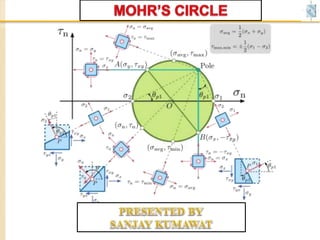
- 2. This graphical representation is extremely useful because it enables you to visualize the relationships between the normal and shear stresses acting on various inclined planes at a point in a stressed body. Using Mohr’s Circle you can also calculate principal stresses, maximum shear stresses and stresses on inclined planes.
- 3. NUMERICAL
- 5. Given Data:- σ1 = 120 N/mm2 (Tensile), σ2 = 60 N/mm2 (Tensile), θ = 30o Scale:- 1cm = 10 N/mm2 Then σ1 = 120/10 = 12 cm σ2 = 60/10 = 6 cm
- 6. σ1 = 120 N/mm2 (Tensile) = 12 cm, σ2 = 60 N/mm2 (Tensile) = 6cm, θ = 30o Scale:- 1cm = 10 N/mm2 1. Take any point A and draw a horizontal line through A. A. B σ1 (12 cm) σ2 (6 cm) O E D 2θ C θ 2. Take AB = σ1 = 12 cm and AC = σ2 = 6 cm 3. With BC as diameter (i.e. BC = 12-6 = 6cm) describe a circle. 4. Let “O” is the centre of the circle. Draw a circle with radius 6 cm 5. Through O, draw a line OE making an angle 2θ (i.e 2 x 30 = 60o with OB. 6. From E, draw ED perpendicular to CB. 7. Join AE & EC 8. Measure Length AD = 10.50 cm Length ED = 2.60 cm Length AE = 10.82 cm Then, 1. Normal Stress = Length AD x Scale = 10.50 x 10 = 105 N/mm2 Theoretical Results σn = 105 N/mm2 σt = 25.98 N/mm2 σR = 108.16 N/mm2 3. Resultant Stress = Length AE x Scale = 10.82 x 10 = 108.2 N/mm2 2. Tangential or Shear stress = Length ED x Scale = 2.60 x 10 = 26 N/mm2 AD = 10.50 cm DE=2.60cm Check the results with the solution ф MOHR’S CIRCLE σn σt
- 7. MOHR’S CIRCLE PROOFMOHR’S CIRCLE PROOF
- 9. A C E DO B 2θф Max Normal Stress σn = σ1 σn σt σR Min Normal Stress σn = σ2σ2 σ1 IMPORTANT POINTS
- 14. σ1 = 200 N/mm2 (Tensile) = 10 cm, σ2 = -100 N/mm2 (Comp.) = 5cm, θ = 30o Scale:- 1cm = 20 N/mm2 Theoretical Results σn = 125 N/mm2 σt = 129.9 N/mm2 σR = 180.27 N/mm2 (σt)max = 129.9 N/mm2 ф = 46o 6’ 1. Take any point A and draw a horizontal line through A on both sides. Check the results with the solution MOHR’S CIRCLE Compressive (-) Tensile (+) y x 2θ =60o θ ф C A O D E σ2= -5cm (100) σ1 = 10 cm (200) 6.25 cm (σn) 6.5cm(σt) 2. Take AB = σ1 = 10 cm and AC = σ2 = -5 cm 3. With BC as diameter (i.e. OB = 7.5 cm) describe a circle. 4. Let “O” is the centre of the circle. Draw a circle with OB or OC 5. Through O, draw a line OE making an angle 2θ (i.e 2 x 30 = 60o with OB. 6. From E, draw ED perpendicular to CB. 8. Measure Length AD = 6.25 cm Length ED = 6.5 cm Length AE = 9.0 cm B 7. Join AE & EC σn = Length AD x Scale = 6.25 x 20 = 125 N/mm2 σR = Length AE x Scale = 9.0 x 20 = 180 N/mm2 σt = Length ED x Scale = 6.5 x 20 = 130 N/mm2 ф = 46o
- 15. NUMERICAL
- 17. σ1 = 65 N/mm2 (Tensile) = 6.5 cm, σ2 = 35 N/mm2 (Tensile) = 3.5 cm, Scale:- 1cm = 10 N/mm2 Theoretical Results σn = 75N/mm2 σt = 15 N/mm2 1. Take any point A and draw a horizontal line through A. Check the results with the solution MOHR’S CIRCLE фA L O B G C E M D F Ʈ = 25 N/mm2 (Shear Stress) = 2.5 cm , θ = 45o σ2 = 3.5 cm (35) σ1 = 6.5cm (65) Ʈ = 2.5cm (25) Ʈ=2.5cm (25) 2. Take AB = σ1 = 6.5 cm and AC = σ2 = 3.5 cm 3. Draw perpendicular at B & C and cut off BF & CG = Ʈ = 2.5cm 4. Let “O” is the centre of the circle at intersection. Draw a circle with OF or OG 5. Through O, draw a line OE making an angle 2θ (i.e 2 x 45 =90o with OF. 6. From E, draw ED perpendicular to AB. 8. Measure Length AD = 7.5 cm Length ED = 1.5 cm 7. Join AE σn = Length AD x Scale = 7.5 x 10 = 75 N/mm2 σt = Length ED x Scale = 1.5 x 10 = 15 N/mm2 7.5 cm (σn) 1.5cm(σt)
- 19. σ1 = 20 N/mm2 (Tensile) = 10 cm, σ2 = 10 N/mm2 (Tensile) = 5 cm, Scale:- 1cm = 2 N/mm2 1. Take any point A and draw a horizontal line through A. MOHR’S CIRCLE A L O B G C M F Ʈ = 10 N/mm2 (Shear Stress) = 5 cm σ2 = 5 cm (10) σ1 = 10 cm (20) Ʈ = 5cm (10) Ʈ=5cm 10) 2. Take AB = σ1 = 10 cm and AC = σ2 = 5 cm 3. Draw perpendicular at B & C and cut off BF & CG = Ʈ = 5cm 4. Let “O” is the centre of the circle at intersection. Draw a circle with OF or OG 7. Measure angle 2θ angle FOB = 63.7o 6. Measure Length AM = 13.17.5 cm Length AL = 1.91 cm Major Principal stresses = Length AM x Scale = 13.1 x 2 = 26.2 N/mm2 13.1 cm 1.91 cm Minor Principal stresses = Length AL x Scale = 1.91 x 2 = 9.82 N/mm2 63.7o 5. Mark M & L at the intersection of circle on AB Location of principal planes 2θ = 63.7o, θ = 31.85o Second Principal Plane θ + 90o = 121.85o
- 21. σ1 = 30 N/mm2 (Tensile) = 15 cm, σ2 = 10 N/mm2 (Tensile) = 5 cm, Scale:- 1cm = 2 N/mm2 1. Take any point A and draw a horizontal line through A. MOHR’S CIRCLE A L O B G C M F Ʈ = 10 N/mm2 (Shear Stress) = 5 cm σ2 = 5 cm (10) σ1 = 15 cm (30) Ʈ = 5cm (10) Ʈ=5cm 10) 2. Take AB = σ1 = 15 cm and AC = σ2 = 5 cm 3. Draw perpendicular at B & C and cut off BF & CG = Ʈ = 5 cm 4. Let “O” is the centre of the circle at intersection. Draw a circle with OF or OG 7. Measure angle 2θ angle FOB = 45o 6. Measure Length AM = 7.5 cm Length AL = 1.5 cm Major Principal stresses = Length AM x Scale = 17.1 x 2 = 34.2 N/mm2 17.1 cm 2.93 cm Minor Principal stresses = Length AL x Scale = 2.93 x 2 = 5.86 N/mm2 45o 5. Mark M & L at the intersection of circle on AB H Max. Shear Stress Location of principal planes 2θ = 45o, θ = 22.5o Second Principal Plane θ + 90o = 112.5o 8. Ʈmax = Length OH x Scale = 7.05 X 20 = 14.1 N/mm2