Call Girls In Kotla Mubarakpur Delhi ❤️8448577510 ⊹Best Escorts Service In 24...
Gear Drives.pptx
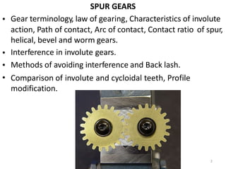
1. SPUR GEARS
Gear terminology, law of gearing, Characteristics of involute
•
action, Path of contact, Arc of contact, Contact ratio
helical, bevel and worm gears.
Interference in involute gears.
Methods of avoiding interference and Back lash.
of spur,
•
•
• Comparison of
modification.
involute and cycloidal teeth, Profile
2
2. Introduction
• Let the wheel A be keyed to the rotating shaft and the wheel B to the shaft, to be
rotated.
A little consideration will show, that when the wheel A is rotated by a rotating
shaft, it will rotate the wheel B in the opposite direction as shown in Fig. (a).
The wheel B will be rotated (by the wheel A) so long as the tangential force exerted
by the wheel A does not exceed the maximum frictional resistance between the two
wheels.
But when the tangential force (P) exceeds the frictional resistance (F), slipping will
take place between the two wheels. Thus the friction drive is not a positive drive.
•
•
•
In order to avoid the slipping, a
number of projections (called
teeth) as shown in Fig. (b), are
provided on the periphery of the
wheel A, which will fit into the
corresponding recesses on the
periphery of the wheel B. A friction
wheel with the teeth cut on it is
known as toothed
whee
3
l/2
o
9
r
/2
g
01
e
6
ar.
3
3. TYPES OF GEARS
1. According to the
shafts.
Parallel
1.Spur Gear
2.Helical Gear
position of axes of the
a.
3.Rack and Pinion
Intersecting
Bevel Gear
Non-intersecting and
b.
c. Non-parallel
worm and worm gears
4
4. SPUR GEAR
• Teeth is parallel to axis
of rotation
Transmit power from
one shaft to another
parallel shaft
Used in Electric
screwdriver, oscillating
sprinkler, windup alarm
clock, washing machine
and clothes dryer
•
•
5
6. Helical Gear
• The teeth on helical gears are cut at an angle to the face of the
gear
• This gradual engagement makes helical gears operate much
more smoothly and quietly than spur gears
• One interesting thing about helical gears is that if the angles
of the gear teeth are correct, they can be mounted on
perpendicular
degrees
shafts, adjusting the rotation angle by 90
7
7. Herringbone
• To avoid axial thrust, two
helical gears of opposite
hand can be mounted side
by side, to cancel resulting
thrust forces
gears
• Herringbone gears are
mostly used on heavy
machinery.
8
8. Rack and pinion
• Rack and pinion gears are used to convert rotation (From the
pinion) into linear motion (of the rack)
• Aperfect example of this is the steering system on many cars
9
9. Bevel gears
• Bevel gears are useful when the direction of a shaft's rotation needs to
be changed
• They are usually mounted on shafts that are 90 degrees apart, but can
be designed to work at other angles as well
• The teeth on bevel gears can be straight, spiral or hypoid
• locomotives, marine applications, automobiles, printing presses,
cooling towers, power plants, steel plants, railway track inspection
machines, etc.
10
11. Hareesha N G, Dept of Aer
WORMAND WORM GEAR
• Worm gears are used when large gear reductions are needed. It is common for
worm gears to have reductions of 20:1, and even up to 300:1 or greater
• Many worm gears have an interesting property that no other gear set has: the worm
can easily turn the gear, but the gear cannot turn the worm
• Worm gears are used widely in material handling and transportation machinery,
machine tools, automobiles etc
12
13. Introduction
Sometimes, two or more gears are made to mesh
with each other to transmit power from one shaft
to another
. Such a combination is called gear train
or train of toothed wheels.
The nature of the train used depends upon the
•
•
velocity ratio required and
the axes of shafts.
the relative position of
• A gear train may consist
gears.
of spur, bevel or spiral
3
14. Types of Gear Trains
• Following are the different types of gear
the arrangement of wheels :
trains, depending upon
1.
2.
3.
4.
Simple gear train
Compound gear train
Reverted gear train
Epicyclic gear train
• In the first three types of gear trains, the axes of the shafts over
which the gears are mounted are fixed relative to each other.
• But in case of epicyclic gear trains, the axes of the shafts on
the gears are mounted may move relative to a fixed axis.
which
4
15. Simple Gear Train
• When there is only one gear on each shaft, as shown in Fig., it is
known as simple gear train.
The gears are represented by their pitch circles.
When the distance between the two shafts is small, the two gears 1
and 2 are made to mesh with each other to transmit motion from
one shaft to the other, as shown in Fig. (a).
Since the gear 1 drives the gear 2, therefore gear 1 is called the driver
and the gear 2 is called the driven or follower.
•
•
•
• It may be noted that the
motion of driving gear.
motion of the driven gear is opposite to the
5
20. Compound Gear Train
• When there are more than one gear on a shaft, as shown in
Fig. , it is called a compound train of gear.
• We have seen that the idle gears, in a simple train of
do not effect the speed ratio of the system.
gears
• But these gears are useful in bridging over the space
between the driver and the driven.
10
21. Compound Gear Train ( Continued)
• But whenever the distance between the driver and the driven or
follower has to be bridged over by intermediate gears and at the
same time a great ( or much less ) speed ratio is required, then the
advantage of intermediate gears is increased by providing compound
gears on intermediate shafts.
In this case, each intermediate shaft has two gears rigidly fixed to it
so that they may have the same speed.
One of these two gears meshes with the driver and the other with
•
•
the driven or follower attached to the next shaft as shown in Fig.
11
22. In a compound train of gears, as shown in Fig. 13.2, the gear 1 is the driving gear mounted on
gears 2 and 3 are compound gears which are mounted on shaft B. The gears 4 and 5 are also
shaftA
compound gears which
Let
are mounted on shaft C and the gear 6 is the driven gear mounted
N 1= Speed of driving gear 1
T, = Number of teeth on driving gear 1
N 2 N3 ..., N6 = Speed of respective gears in r.p.m., and
on shaft D.
T2 ,T3"" T6 = Number of teeth on respective
gears.
Since gear 1 is in mesh with gear 2, therefore its speed ratio is
T2
I
i
N]
N2
...(i)
Driver Compound
for gears 3 and 4 speed ratio
Similarly is
N3
N4
for gears 5 and 6 speed ratio is
N5
N6
The speed ratio of compound gear
T4
1
3
...(ii)
and
T6
T5
train is
...(iii)
obtained by multiplying
.'.
the equations and (iii),
(i), (ii)
_ T2 x T4
X
T1xT3xT5
"N,
N6
T6
or
Since gear 2 and 3 are mounted
1
h/a
2f7t/2C
01
,4
therefore N4 = N5'
on one shaft B, therefore N2 = N3"
Similarly
gears 4 and 5 are mounted on
12