
Recomendados
Recomendados
Más contenido relacionado
La actualidad más candente
La actualidad más candente (20)
Destacado
Destacado (13)
Similar a L33 1 ph-tr(1)
Similar a L33 1 ph-tr(1) (20)
Más de Satyakam
Último
Último (20)
L33 1 ph-tr(1)
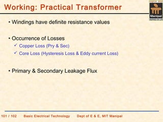
- 1. • Windings have definite resistance values • Primary & Secondary Leakage Flux • Occurrence of Losses Copper Loss (Pry & Sec) Core Loss (Hysteresis Loss & Eddy current Loss) Working: Practical Transformer 101 / 102 Basic Electrical Technology Dept of E & E, MIT Manipal
- 2. Working: Practical Transformer - No Load mco IˆIˆIˆ += 101 / 102 Basic Electrical Technology Dept of E & E, MIT Manipal N1 N2 V2V1 Io E1 E2 • Primary draws a current IO called No-load current • IO has two components: IC = iron loss component – supplies eddy current loss Im = magnetization component – sets up magnetic field • Primary winding impedance Z1 = R1+jX1 • E1 = V1 – IOZ1 • A part of primary flux links with secondary • E2 is induced • I2 = 0. Therefore, E2 = V2
- 3. Working: Practical Transformer - On Load 2 1 2' 2 Iˆ N N Iˆ = 101 / 102 Basic Electrical Technology Dept of E & E, MIT Manipal LOAD N1 N2 V2V1 I1 E1 E2 I2 • Primary draws a current IO=IC+Im • Secondary supplies I2 to load • A current I2 1 is drawn by primary to balance the load current • Total primary current I1 = IO+I2 1 • E1 = V1 – I1Z1 • Z2 = R2+jX2 = secondary winding impedance • V2 = E2 – I2Z2
- 4. 101 / 102 Basic Electrical Technology Dept of E & E, MIT Manipal Equivalent circuit RC XM Ic Im Io Core: Io = No load current component Ic = Core loss current component Im = Magnetizing current component RC = core loss equivalent XM = magnetization equivalent Primary Side: R1 X1 Secondary Side: R2 X2
- 5. 101 / 102 Basic Electrical Technology Dept of E & E, MIT Manipal • Resistances & Reactances are can be transferred to either side • All quantities are referred to either primary side or secondary side Ideal Transformer V1 E1 I1 R1 X1 Rc Xm Ic Im Io R2 X2 I2 ZL E2 V2 I'2 N1 N2 Equivalent circuit representation
- 6. 101 / 102 Basic Electrical Technology Dept of E & E, MIT Manipal Equivalent circuit as referred to secondary Equivalent primary winding resistance as referred to secondary 1 2 1 2 1 N N RR =′ Equivalent primary winding reactance as referred to secondary 1 2 1 2 1 N N XX =′ E2 I1 1 R1 1 X1 1 V1 1 R1 C X1 m I1 c I1 m I1 o R2 X2 ZLV2 I2 K N N == 1 2 1 1 1 V V
- 7. 101 / 102 Basic Electrical Technology Dept of E & E, MIT Manipal Approximate equivalent circuit • No load current Io is quite small as compared to rated primary current • Therefore, Voltage drops in primary due to Io is negligibly small • Shunt branch circuit is shifted towards the supply side R2 X2 E2 I1 1 V1 1 R1 c X1 m I1 c I1 m I1 o ZLV2 I2 R1 1 X1 1
- 8. 101 / 102 Basic Electrical Technology Dept of E & E, MIT Manipal Approx. equivalent circuit referred to secondary I1 1 V1 1 R1 c X1 m I1 c I1 m I1 o ZLV2 I2 R2e X2e Equivalent winding resistance 2 1 12 R+= RR e Equivalent winding reactance 2 1 12 XXX e += Equivalent winding impedance eee jXRZ 222 +=
- 9. 101 / 102 Basic Electrical Technology Dept of E & E, MIT Manipal Approx. equivalent circuit referred to primary Equivalent winding resistance 1 211 R+= RR e Equivalent winding reactance 1 211 XXX e += Equivalent winding impedance eee jXRZ 111 += I1 V1 Rc Xm Ic Im Io Z1 LV1 2 I1 2 R1e X1e
- 10. Exercise A 15 kVA, 2200 / 110 V, 50 Hz, 1φ transformer has pry & sec winding resistances of 1.75 Ω & 0.0045 Ω and pry & sec winding reactances of 2.6 Ω & 0.0075 Ω respectively. Determine (a) equivalent resistance, reactance & impedance as referred to pry (b) equivalent resistance, reactance & impedance as referred to sec (c) total copper loss Ans: (a) 3.55 Ω, 5.6 Ω, 6.63 ∠57.63o (b) 0.008875 Ω, 0.014 Ω, 0.0166 ∠57.56o (c) 165 W 101 / 102 Basic Electrical Technology Dept of E & E, MIT Manipal