
Recomendados
Más contenido relacionado
Más de Scottish Home Improvements
Más de Scottish Home Improvements (15)
Último
Último (20)
Scottish home improvement denver james hardie product data
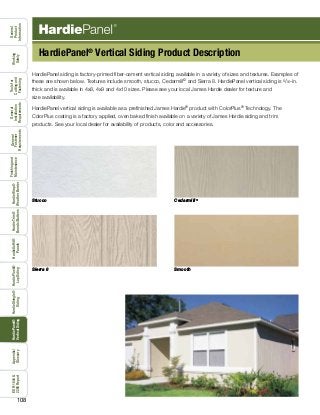
- 1. 108 General Product Information Working Safely Toolsfor Cuttingand Fastening General Installation Requirements General Fastener Requirements Finishingand MaintenanceHardieTrim® Boards/Battens HardieWrap® WeatherBarrier HardieSoffit® Panels HardiePlank® LapSiding HardieShingle® Siding HardiePanel® VerticalSiding ESR-1844& 2290Report Appendix/ Glossary HardiePanel® Vertical Siding Product Description HardiePanel siding is factory-primed fiber-cement vertical siding available in a variety of sizes and textures. Examples of these are shown below. Textures include smooth, stucco, Cedarmill© and Sierra 8. HardiePanel vertical siding is 5/16-in. thick and is available in 4x8, 4x9 and 4x10 sizes. Please see your local James Hardie dealer for texture and size availability. HardiePanel vertical siding is available as a prefinished James Hardie® product with ColorPlus® Technology. The ColorPlus coating is a factory applied, oven baked finish available on a variety of James Hardie siding and trim products. See your local dealer for availability of products, color and accessories. Stucco Cedarmill © Sierra 8 Smooth
- 2. 109 General Product Information Toolsfor Cuttingand Fastening General Installation Requirements General Fastener Requirements Finishingand MaintenanceHardieTrim® Boards/Battens HardieWrap® WeatherBarrier HardieSoffit® Panels HardiePlank® LapSiding HardieShingle® Siding HardiePanel® VerticalSiding ESR-1844& 2290Report Appendix/ Glossary Working Safely TIP: It is common practice to mark panels for cutting with a chalk line. Blue chalk is recommended because it washes off. Red chalk is considered permanent and may bleed through lighter colored paints. TIP: For Sierra 8 panels, double studs at each panel joint allows fasten- ers to be placed outside of panel grooves. Water resistive barrier Panel edges land in the middle of a stud. getting started First locate the lowest point of the sheathing or sill plate, and begin installation on that wall. 1) Measure up from the sill plate the height of the panels at either end of the wall and snap a straight, level chalk line between the marks as a reference line. That line is for guidance in positioning the top edge of the panels. Check the reference line with a 4-ft. level. 2) Starting on one end and working across the wall, measure and trim the first panel making sure that the edge falls in the middle of a stud. 3) Using the chalk line as a guide along the panel’s top edge, carefully position the panel and secure it with suitable fasteners and fastener spacing for the particular application as noted in the ESR-1844. 4) As installation continues, check the vertical edge of each panel with a 4-ft. level. Note: James Hardie requires a minimum 3/8” capillary break (Rainscreens, Furring, Etc.), when installing HardiePanel on a Multi-Family/Commercial project. Check each panel with a 4-ft. level 12.1 Installation of HardiePanel ® Vertical Siding TIP: Install flashing over the footing/foundation and extend the panel over the flashing just below the sill plate. Do not extend siding beyond the required grade clearances. 12.2
- 3. 110 General Product Information Working Safely Toolsfor Cuttingand Fastening General Installation Requirements General Fastener Requirements Finishingand MaintenanceHardieTrim® Boards/Battens HardieWrap® WeatherBarrier HardieSoffit® Panels HardiePlank® LapSiding HardieShingle® Siding HardiePanel® VerticalSiding ESR-1844& 2290Report Appendix/ Glossary The caulk joint method is not recommended for the ColorPlus® products WARNING! vertical joint treatment Treat vertical joints in HardiePanel ® vertical siding by using one of the following four methods: 1) Install the panels in moderate contact. 2) Leave an appropriate gap between panels (1/8 in. is the most common), and caulk using a high-quality paintable caulk, that meets ASTM C-834 or C-920 requirements. (Not recommended for ColorPlus) Panels may be installed first with caulk applied in the joints after installation; or as an option, after the first panel is installed, apply a bead of caulk along the panel edge. When the next panel is installed against the first, the edge embeds in the applied caulk creating a thorough seal between the edges of the panels. 3) Vertical joints may be covered with wood or fiber-cement batten strips. If James Hardie® siding or trim products are ripped and used as batten strips, paint or prime the cut edges. Batten strips should span the vertical joint by at least 3/4 in. on each side. 4 Metal or PVC “H” moldings can be used to join two sections of HardiePanel siding. TIP: Stainless steel fasteners are recommended when installing James Hardie products. 6d screw 2 51 9 4d common 1 .113” x .267” x 1.5” ring shank siding nail 5 .091” x .225” x 1.5” roofing nail9 No. 11ga 1.25” long ET&F13 [AKN100-0150NA] .100” x .25” x 1.5” 2 .113” x .267” x 2” 6d common Fastening Substrate Fastening TypesApproved Fastener 1 2 9 wood studs 24” o.c. 16” o.c. 7 13 steel studs 16” o.c or 24” o.c. Ribbed Bugle-Head No. 8 (.323” x 1”) screw7 Installation of HardiePanel ® Vertical Siding (continued) 3 Battened joint 4 H-Channel joint 1 Moderate contact joint with joint flashing 2 Caulked joint Panels are butted together lightly. 1/8-in. gap left between panels is filled with caulk. (not applicable with ColorPlus) HardieTrim® batten board covers the joint between panels. Note: The following outlines the recommended applications for ColorPlus and Primed panels. Not all designs will be suitable for every application: • Exposed fasteners or battens is the recommended application for ColorPlus products • Do not use touch-up over fastener heads for smooth ColorPlus products - primed panel recommended • For ColorPlus panel applications that require fasteners in the field, it is acceptable to use touch-up over fasteners for Cedarmill and Stucco panel only, but correct touch-up application is important. Some colors may show touch-up when applied over fasteners. Trim is recommended to cover joints when appropriate. A manufactured H-channel captures the vertical edges of the panels. 12.3 12.4 12.612.5 Hardiepanel siding fastener specifications The Fastener Specifications table shows fastener options for a variety of different nailing substrates. Please refer to the applicable ESR report online (see back page) to determine which fastener meets your wind load
- 4. 111 General Product Information Toolsfor Cuttingand Fastening General Installation Requirements General Fastener Requirements Finishingand MaintenanceHardieTrim® Boards/Battens HardieWrap® WeatherBarrier HardieSoffit® Panels HardiePlank® LapSiding HardieShingle® Siding HardiePanel® VerticalSiding ESR-1844& 2290Report Appendix/ Glossary Working Safely Do not bridge floors with panel siding. A horizontal joint shall always be created between floors. WARNING! horizontal joint treatment In some applications such as multi-story structures or at gable ends, it may be necessary to stack HardiePanel ® siding. The horizontal joints created between panels must be flashed properly to minimize water penetration. Treat horizontal panel joints by using one of the following methods: 1) After installing the lower course of panel siding, install vinyl or coated aluminum “Z” flashing at the top edge of the panel. Make sure that the flashing is sloped away from the wall and does not rest flat on the top edge of the panel. Install the second level or gable panels leaving a 1/4-in. minimum gap between the bottom of the panel and the Z flashing. This gap should never be caulked. 2) As an alternative, if a horizontal band board is used at the horizontal joint, flashing must extend over the panel edge and trim attachment. Flashing for both treatments must slip behind the water-resistive barrier. TIP: For the most symmetrical looking wall, plan the installation so that a full panel is centered on the wall or gable with equal-size panels cut for each end. As an alternative, plan the installation so that a full panel is located on either side of the wall center, again leaving equal-size panels on each end. These strategies might entail a center- ed framing layout. Choose the strategy that looks the best and uses material most efficiently. TIP: For best looking installation of HardiePanel Select Sierra 8 siding, carefully align vertical panel grooves at 1st to 2nd story or gable junctures. 12.7 12.8 Water-resistive barrier Flashing Upper panel furring strip furring strip Lower panel Decor- ative band board Water-resistive barrier Flashing Upper panel 6mm (¼”) Gap 6mm (¼”) Gap Don’t caulk gap between flashing and upper panel. Don’t caulk gap between flashing and upper panel. Water-resistive barrier Upper panel Upper panel Lower panel Lower panel Decorative band board 1 Simple horizontal joint 2 Band-board joint Water-resistive barrier
- 5. 112 General Product Information Working Safely Toolsfor Cuttingand Fastening General Installation Requirements General Fastener Requirements Finishingand MaintenanceHardieTrim® Boards/Battens HardieWrap® WeatherBarrier HardieSoffit® Panels HardiePlank® LapSiding HardieShingle® Siding HardiePanel® VerticalSiding ESR-1844& 2290Report Appendix/ Glossary In panel installations, trim is typically overlaid on top of the panel. Special attention needs to be paid to trim flashing at the tops of openings. Below is one method for properly flashing trim in a panel application: 1) After installing the window, cut and install a 1/4-in. thick shim above the window. The shim should be the same width as the trim, and it should be as long as the width of the window. 2) Over the shim, install flashing wide enough to cover thickness of the trim and long enough to cover the trim head piece. 3) Install the panel to the window and around the shim taking care not to damage the flashing and leaving a 1/4-in. gap between the panel and the horizontal part of the flashing. 4) Install the trim around the win- dow, slipping the head piece under the installed flashing. 1 Install 1 /4-in. thick shim over the window. 2 Install flashing over the shim and under the water- resistive barrier. 3 Cut and fit panel around the shim and flashing, Leave 1 /4-in. gap between the flashing and the upper panel. 4 Install window trim under the flashing. windows, doors, and other wall penetrations 12.9 12.10 12.11 Installation of HardiePanel ® Vertical Siding (continued)
- 6. 113 General Product Information Toolsfor Cuttingand Fastening General Installation Requirements General Fastener Requirements Finishingand MaintenanceHardieTrim® Boards/Battens HardieWrap® WeatherBarrier HardieSoffit® Panels HardiePlank® LapSiding HardieShingle® Siding HardiePanel® VerticalSiding ESR-1844& 2290Report Appendix/ Glossary Working Safely RAIN SCREENS Attaching panel siding to wood furring: When attaching panel siding products over wood furring, the typical fastener used is the 6d common 2” long nail. This fastener is going to be the shortest fastener approved for fastening panel siding products into wood, therefore the furring must be a minimum of 1-11/16” thick to achieve the same values as ESR 1844, Table 4, given stud spacing, building height, and exposure category. 12.1312.12 The Use of Rain Screen Systems: James Hardie will support the use of its exterior siding products with rainscreen systems, but does not take sole responsibility for the entire wall assembly or system. James Hardie expects the designer or builder using our components as part of the rainscreen system to: • Adhere to all the installation requirements listed in the relevant product installation instructions. • Provide adequate details for water management. • Make the decision about the use of rainscreen. • James Hardie products does not recommend “drainage mats” or drainage boards” to provide the necessary capillary break behind our siding. These products can compress during the installation process, impairing the drainage channels and further causing a “wavy” appearance in the plank or panel products. • Understand the interaction between system components and how each of the components in the system interacts. • Design of the building envelope accounting for both interior and exterior moisture control. Installation Over Furring: When installing James Hardie Siding products over furring the question arises what thickness of furring can be used as an alternate to normal metal or wood studs specified in the ESR 1844 & 2290 Report. General rule of thumb is, the specific ESR 1844 & 2290 fastener must be installed into a material that has the same or better holding power than that specified in the ESR 1844 & 2290 and with the same penetration as the ESR 1844 & 2290 fastener. Note: The ESR 1844 & 2290 is the primary code compliance document James Hardie utilizes, but for other common applications and/or products, additional code compliance documentation and/or fastener specifications may exist. For special circumstances out side the scope of the ESR 1844 & 2290, please contact James Hardie’s Technical Services. When reviewing the following details for attaching to wood furring or framing, an important consideration is that the fastener chosen must be fully encompassed by a wood substrate - the furring may count as all or part of the necessary penetration if it has been proven that the furring and/or wood substrate has the same or better holding power as a timber stud. Design responsibility In all cases it is the sole responsibility of the architect, envelope engineer or specifier to identify moisture related risks associated with any particular building design and to make any appropriate adjustments or modifications to the installation guidelines given by manufacturers. Wall construction and design must effectively manage moisture, considering both the interior and exterior environment of the building. It is deemed an acceptable practice to not fasten along the top and bottom plates for the 5/16” HardiePanel configurations listed in the ESR 1844, Table 4 using the following fastener type: • 0.091” shank X 0.225” HD X 1.5” long ring shank nail • Min. No. 8 X 0.311 HD X 1” ribbed bugle head screw • 0.10 X 0.25” HD X 1.5” long ET&F pin or equivalent • 6d common 2” long nail Conditions of use: • This practice is acceptable for transverse load only. • This practice is not acceptable for racking shear values or in- plane forces other than perpendicular/normal wind forces. • All vertical joints shall occur over framing. • All other James Hardie Installation Requirements shall be followed. Attaching panel siding to steel furring: When attaching panel siding products to metal furring, the steel furring must be a minimum 20 gauge steel. A fastener should be chosen out of the ESR 1844, Table 4, which is approved for attaching to steel framing. Two general rules that should be considered when choosing a fastener is that a nail (pin) must penetrate steel furring ¼”, and screws must penetrate steel furring 3 full threads. Therefore, if the rules for steel fastening are followed – given stud spacing, building height, and exposure category – the values are the same as ESR 1844, Table 4 states for the chosen fastener. 12.14 12.15
- 7. 114 HS1236 - P1/3 1/13 GENERAL REQUIREMENTS: INSTALLATION: Fastener Requirements Position fasteners 3/8" from panel edges and no closer than 2" away from corners. Do not nail into corners. HardiePanel Vertical Siding Installation • Framing must be provided at horizontal and vertical edges for nailing. • HardiePanel vertical siding must be joined on stud. • Double stud may be required to maintain minimum edge nailing distances. Figure 2 Caulk Joint leave appropriate gap between panels, then caulk* water-resistive barrier 2 x 4 stud “H” Joint water-resistive barrier 2 x 4 stud Batten Joint water-resistive barrier 2 x 4 stud S M O O T H C E D A R M I L L © S E L E C T S I E R R A 8 S T U C C O Figure 1 James Hardie® products contain respirable crystalline silica, which is known to the State of California to cause cancer and is considered by IARC and NIOSH to be a cause of cancer from some occupational sources. Breathing excessive amounts of respirable silica dust can also cause a disabling and potentially fatal lung disease called silicosis, and has been linked with other diseases. Some studies suggest smoking may increase these risks. During installation or handling: (1) work in outdoor areas with ample ventilation; (2) use fiber cement shears for cutting or, where not feasible, use a HardieBlade® saw blade and dust-reducing circular saw attached to a HEPA vacuum; (3) warn others in the immediate area; (4) wear a properly-fitted, NIOSH-approved dust mask or respirator (e.g. N-95) in accordance with applicable government regulations and manufacturer instructions to further limit respirable silica exposures. During clean-up, use HEPA vacuums or wet cleanup methods - never dry sweep. For further information, refer to our installation instructions and Material Safety Data Sheet available at www.jameshardie.com or by calling 1-800-9HARDIE (1-800-942-7343). FAILURE TO ADHERE TO OUR WARNINGS, MSDS, AND INSTALLATION INSTRUCTIONS MAY LEAD TO SERIOUS PERSONAL INJURY OR DEATH. SD050905 • These instructions to be used for residential single family installations only. For Commercial / Multi-Family installation requirements go to www.JamesHardieCommercial.com • HardiePanel® vertical siding can be installed over braced wood or steel studs spaced a maximum of 24" o.c.See genernal fastening requirements.Irregularities in framing and sheathing can mirror through the finished application.James Hardie recommends installing HardiePanel on a capillary break (rainscreen/furring) as a best practice. • Information on installing James Hardie products over foam can be located in JH Tech Bulletin 19 at www. jamehardie.com • A water-resistive barrier is required in accordance with local building code requirements. The water-resistive barrier must be appropriately installed with penetration and junction flashing in accordance with local building code requirements. James Hardie will assume no responsibility for water infiltration. James Hardie does manufacture HardieWrap® Weather Barrier, a non-woven non-perforated housewrap1, which complies with building code requirements. • When installing James Hardie products all clearance details in figs. 5,6,7,8,9,10&11 must be followed. • Adjacent finished grade must slope away from the building in accordance with local building codes - typically a minimum of 6" in the first 10'. • Do not install James Hardie products, such that they may remain in contact with standing water. • HardiePanel vertical siding may be installed on vertical wall applications only. • DO NOT use HardiePanel vertical siding in Fascia or Trim applications. • Some application are not suitable for ColorPlus. Refer to ColorPlus section page 3. • DO NOT use stain, oil/alkyd base paint, or powder coating on James Hardie® Products. • For larger projects, including commercial and multi-family projects, where the span of the wall is significant in length, the designer and/or architect should take into consideration the coefficient of thermal expansion and moisture movement of the product in their design. These values can be found in the Technical Bulletin #8 “Expansion Characteristics” at www.JamesHardie.com. Figure 4 Recommendation: When installing Sierra 8, provide a double stud at panel joints to avoid nailing through grooves. Figure 3 moderate contact keep fasteners 2" away from corners plate keep nails 3/8" min. from panel edges water-resistive barrier stud HardiePanel vertical siding 3/8" sheathing upper panel 1/4" gap Z-flashing Do not Caulk lower panel upper panel 1/4" gap Z-flashing Do not Caulk lower panel decorative band board water-resistive barrier water-resistive barrier (Not applicable to ColorPlus® Finish) *Apply caulk in accordance with caulk manufacturer’s written application instructions. Joint Treatment • Vertical Joints - Install panels in moderate contact (fig. 1), alternatively joints may also be covered with battens, PVC or metal jointers or caulked (Not applicable to ColorPlus® Finish) (fig. 2). • Horizontal Joints - Provide Z-flashing at all horizontal joints (fig. 3). 1 For additional information on HardieWrap™ Weather Barrier, consult James Hardie at 1-866-4Hardie or www.hardiewrap.com INSTALLATION REQUIREMENTS RESIDENTIAL SINGLE FAMILY ONLY - PRIMED & COLORPLUS® PRODUCTS Visit www.jameshardie.com for the most recent version. Vertical Siding EFFECTIVE SEPTEMBER 2013 OUTDOORS 1.Position cutting station so that wind will blow dust away from user and others in working area. 2.Use one of the following methods: a.Best: i.Score and snap ii.Shears (manual,electric or pneumatic) b.Better: i.Dust reducing circular saw equipped with a HardieBlade® saw blade and HEPA vacuum extraction c.Good: i.Dust reducing circular saw with a HardieBlade saw blade (only use for low to moderate cutting) INDOORS 1. Cut only using score and snap, or shears (manual, electric or pneumatic). 2. Position cutting station in well-ventilated area - NEVER use a power saw indoors - NEVER use a circular saw blade that does not carry the HardieBlade saw blade trademark - NEVER dry sweep – Use wet suppression or HEPA Vacuum Important Note:For maximum protection (lowest respirable dust production),James Hardie recommends always using“Best”-level cutting methods where feasible. NIOSH-approved respirators can be used in conjunction with above cutting practices to further reduce dust exposures. Additional exposure information is available at www.jameshardie.com to help you determine the most appropriate cutting method for your job requirements.If concern still exists about exposure levels or you do not comply with the above practices,you should always consult a qualified industrial hygienist or contact James Hardie for further information. SD083105 CUTTING INSTRUCTIONSSTORAGE & HANDLING: IMPORTANT: FAILURE TO INSTALL AND FINISH THIS PRODUCT IN ACCORDANCE WITH APPLICABLE BUILDING CODES AND JAMES HARDIE WRITTEN APPLICATION INSTRUCTIONS MAY LEAD TO PERSONAL INJURY,AFFECT SYSTEM PERFORMANCE,VIOLATE LOCAL BUILDING CODES, AND VOID THE PRODUCT ONLY WARRANTY. BEFORE INSTALLATION, CONFIRM THAT YOU ARE USING THE CORRECT HARDIEZONE INSTRUCTIONS. INSTALLATION OF HZ10™ PRODUCTS OUTSIDE AN HZ10® LOCATION WILL VOID YOUR WARRANTY. TO DETERMINE WHICH HARDIEZONE APPLIES TO YOUR LOCATION,VISIT WWW.HARDIEZONE.COM OR CALL 1-866-942-7343 (866 9HARDIE) Store flat and keep dry and covered prior to installation. Installing siding wet or saturated may result in shrinkage at butt joints. Carry planks on edge. Protect edges and corners from breakage. James Hardie is not responsible for damage caused by improper storage and handling of the product.
- 8. 115 HS1236 - P2/3 8/13 Figure 5 Figure 7 Figure 10 Figure 6 joist 1" - 2" min. water resistive barrier siding flashing deck material ledger Figure 8 1"- 2" min. 6" min. bottom plate siding stud concrete foundation 1" - 2" min. Figure 9 CLEARANCES Install siding and trim products in compliance with local building code requirements for clearance between the bottom edge of the siding and the adjacent finished grade. Maintain a minimum 1" - 2" clearance between James Hardie® products and paths, steps and driveways. Maintain a minimum 1" - 2" clearance between James Hardie products and decking material. At the juncture of the roof and vertical surfaces, flashing and counterflashing shall be installed per the roofing manufacturer’s instructions. Provide a minimum 1"- 2" clearance between the roofing and the bottom edge of the siding and trim. Maintain a minimum 1" gap between gutter end caps and siding & trim. fascia siding 1" gutter and end cap Framing Flooring Horizontal Trim Water- Resistive Barrier Sheathing R HardiePanel Do not bridge floors with HardiePanel® siding. Horizontal joints should always be created between floors (fig. 10). Maintain a 1/4" clearance between the bottom of James Hardie products and horizontal flashing. Do not caulk gap. Refer to fig. 3 on page 1. Figure 11 Self-adhering membrane Step flashing Housewrap Drip edge Kickout flashing Self-adhering eaves membrane KICKOUT FLASHING Because of the volume of water that can pour down a sloped roof, one of the most critical flashing details occurs where a roof intersects a sidewall. The roof must be flashed with step flashing. Where the roof terminates, install a kickout to deflect water away from the siding. It is best to install a self-adhering membrane on the wall before the subfascia and trim boards are nailed in place, and then come back to install the kickout. Figure 11, Kickout Flashing To prevent water from dumping behind the siding and the end of the roof intersection, install a "kickout" as required by IRC code R905.2.8.3 : “…flashing shall be a min. of 4” high and 4” wide.” James Hardie recommends the kickout be angled between 100° - 110° to maximize water deflection GENERAL FASTENING REQUIREMENTS Fasteners must be corrosion resistant, galvanized, or stainless steel. Electro-galvanized are acceptable but may exhibit premature corrosion. James Hardie recommends the use of quality, hot-dipped galvanized nails. James Hardie is not responsible for the corrosion resistance of fasteners. Stainless steel fasteners are recommended when installing James Hardie products near the ocean, large bodies of water, or in very humid climates. • Consult applicable product evaluation or listing for correct fastener type and placement to achieve specific design wind loads. • NOTE: Published wind loads may not be applicable to all areas where Local Building Codes have specific jurisdiction. Consult James Hardie Technical Services if you are unsure of applicable compliance documentation. • Drive fasteners perpendicular to siding and framing. • Fastener heads should fit snug against siding (no air space). (fig. A) • Do not over-drive nail heads or drive nails at an angle. • If nail is countersunk, fill nail hole and add a nail. (fig. B) • For wood framing, under driven nails should be hit flush to the plank with a hammer (for steel framing, remove and replace nail). • NOTE: Whenever a structural member is present, HardiePlank should be fastened with even spacing to the structural member. The tables allowing direct to OSB orplywood should only be used when traditional framing is not available. • Do not use aluminum fasteners, staples, or clipped head nails. Figure A Figure B Countersunk, fill & add nail PNEUMATIC FASTENING James Hardie products can be hand nailed or fastened with a pneumatic tool. Pneumatic fastening is highly recommended. Set air pressure so that the fastener is driven snug with the surface of the siding. A flush mount attachment on the pneumatic tool is recommended. This will help control the depth the nail is driven. If setting the nail depth proves difficult, choose a setting that under drives the nail. (Drive under driven nails snug with a smooth faced hammer - Does not apply for installation to steel framing). BLOCKED PENETRATIONS Penetrations such as hose bibs and holes 1 ½” or larger such as dryer vents should have a block of trim around point of penetration.
- 9. 116 HS1236 - P3/3 6/13 COLORPLUS® TECHNOLOGY CAULKING, TOUCH-UP & LAMINATE • Care should be taken when handling and cutting James Hardie® ColorPlus® products. During installation use a wet soft cloth or soft brush to gently wipe off any residue or construction dust left on the product, then rinse with a garden hose. • Touch up nicks, scrapes and nail heads using the ColorPlus® Technology touch-up applicator. Touch-up should be used sparingly. If large areas require touch-up, replace the damaged area with new HardiePanel® siding with ColorPlus Technology. • Laminate sheet must be removed immediately after installation of each course. • Terminate non-factory cut edges into trim where possible, and caulk. Color matched caulks are available from your ColorPlus® product dealer. • Treat all other non-factory cut edges using the ColorPlus Technology edge coaters, available from your ColorPlus product dealer. Note: James Hardie does not warrant the usage of third party touch-up or paints used as touch-up on James Hardie ColorPlus products. Problems with appearance or performance arising from use of third party touch-up paints or paints used as touch-up that are not James Hardie touch-up, will not be covered under the James Hardie ColorPlus Limited Finish Warranty. The following outlines the recommended applications for ColorPlus and Primed panels. Not all designs will be suitable for every application: • Exposed fasteners or battens is the recommended application for ColorPlus panel products • Do not use touch-up over fastener heads for smooth ColorPlus products - primed panel recommended • For ColorPlus panel applications that require fasteners in the field, it is acceptable to use touch-up over fasteners for Cedarmill and Stucco panel only, but correct touch-up application is important. Some colors may show touch-up when applied over fasteners. Trim is recommended to cover joints when appropriate. PAINTING JAMES HARDIE® SIDING AND TRIM PRODUCTS WITH COLORPLUS® TECHNOLOGY When repainting ColorPlus products, James Hardie recommends the following regarding surface preparation and topcoat application: • Ensure the surface is clean, dry, and free of any dust, dirt, or mildew • Repriming is normally not necessary • 100% acrylic topcoats are recommended • DO NOT use stain, oil/alkyd base paint, or powder coating on James Hardie® Products • Apply finish coat in accordance with paint manufacturers written instructions regarding coverage, application methods, and application temperature © 2013 James Hardie Building Products. All rights reserved. TM, SM, and ® denote trademarks or registered trademarks of James HardieTechnology Limited is a registered trademark of James Hardie Technology Limited. RECOGNITION: In accordance with ICC-ES Evaluation Report ESR-1844, HardiePanel® vertical siding is recognized as a suitable alternate to that specified in: the 2006.2009, & 2012 International Residential Code for One-and Two-Family Dwellings and the 2006, 2009, & 2012 International Building Code. HardiePanel vertical siding is also recognized for application in the following: City of Los Angeles Research Report No. 24862, State of Florida listing FL#889, Dade County, Florida NOA No. 02-0729.02, U.S. Dept. of HUD Materials Release 1263c, Texas Department of Insurance Product Evaluation EC-23, City of New York MEA 223-93-M, and California DSA PA-019. These documents should also be consulted for additional information concerning the suitability of this product for specific applications. Additional Installation Information, Warranties, and Warnings are available at www.jameshardie.com CUT EDGE TREATMENT Caulk, paint or prime all field cut edges. James Hardie touch-up kits are required to touch-up ColorPlus products. CAULKING For best results use an Elastomeric Joint Sealant complying with ASTM C920 Grade NS, Class 25 or higher or a Latex Joint Sealant complying with ASTM C834. Caulking/Sealant must be applied in accordance with the caulking/sealant manufacturer’s written instructions. Note: OSI Quad as well as some other caulking manufacturers do not allow tooling. DO NOT caulk nail heads when using ColorPlus products, refer to the ColorPlus touch-up section PAINTING DO NOT use stain, oil/alkyd base paint, or powder coating on James Hardie® Products. James Hardie products must be painted within 180 days for primed product and 90 days for unprimed. 100% acrylic topcoats are recommended. Do not paint when wet. For application rates refer to paint manufacturers specifications. Back-rolling is recommended if the siding is sprayed.