PUMPS+-
•
46 recomendaciones•13,101 vistas

PPT CONSISTS OF VARIOUS PUMPS USED IN A SHIP, DIFFERENT PACKING MATERIALS

Recomendados
Más contenido relacionado
La actualidad más candente
La actualidad más candente (20)
Destacado
Destacado (20)
Similar a PUMPS+-
Similar a PUMPS+- (20)
Último
Último (20)
PUMPS+-
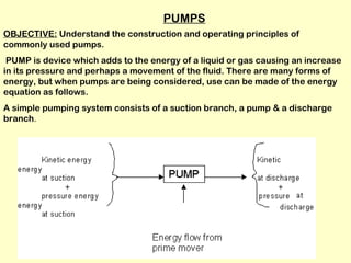
- 1. PUMPS OBJECTIVE: Understand the construction and operating principles of commonly used pumps. PUMP is device which adds to the energy of a liquid or gas causing an increase in its pressure and perhaps a movement of the fluid. There are many forms of energy, but when pumps are being considered, use can be made of the energy equation as follows. A simple pumping system consists of a suction branch, a pump & a discharge branch.
- 2. Names of Pumps used on board • Main Lube oil pump • Jacket cooling pump • Piston cooling pump • Main Seawater Pump • Ballast Pump • Fire & GS pump • Ejector pump
- 3. • M.E. FO Booster pump • Auxiliary Cooling water pump • A/C Cooling water pump • Bilge pump • FO Transfer pump • Heleshaw pump
- 4. • DO Transfer pump • Hydrophor pumps • Sludge pump • Boiler water circulating pump • Boiler feed water pump • FWG Ejector pump • FWG Condensate pump
- 7. Pump characteristics Pump only adds to the energy of the fluid in the system. Energy required to bring the fluid to the pump is an external one and in most practical conditions is provided by the atmospheric pressure. .Reference to the figure, even though liquid on suction side is below the pump center line, still liquid will rise up to the pump center because of external atmospheric pressure acting on surface of liquid; & no pressure acting on other side (i.e. at pump center).
- 8. Portable Positive Displacement pump (variable speed) Coupling guard Pump Motor Suction Discharge Gearbox pipe pipe
- 9. Marine pumps fall into two broad classes: 2.Displacement (self priming) 3.Dynamic Displacement: Liquid or gas is displaced from suction to the discharge by the mechanical variation of the volume of a chamber or chambers. All displacement pumps are self-priming pumps. These pumps include Reciprocating pump, Gear pump, and Screw pump. Dynamic (Centrifugal pumps, Axial pumps) : These dynamic pumps are basically radial flow or axial flow type. Centrifugal pump: Flow through the pump is induced by the centrifugal force imparted to the liquid by the rotation of an impeller or impellers. These pumps are not self-priming pumps and must be primed by gravity supply or by priming equipment external or internal with the pump.
- 10. Heart (Pump)
- 11. PISTON PUMP
- 12. RECIPROCATING-PISTON PUMP (self priming) (Single Acting piston Pump)
- 13. Reciprocating motion of bucket (piston) is obtained through a connecting rod and crank mechanism from an electric motor drive or directly from a steam reciprocating engine. On downward stroke suction valve lifts up against spring and discharge valve remains shut and upward travel discharge valve against spring opens and suction valve remains shut. If the level of liquid to be pumped is below the pump center line, the initial strokes of bucket will draw out air (gas, in case liquid is volatile) from the suction pipe into discharge pipe, creating a low pressure (vacuum) in the suction line. Liquid now rises into suction pipeline under atmospheric pressure, (If the liquid is say water it will theoretically rise up to 10.3 meter and hence pump can theoretically handle a suction lift of 10.3 meter; However in real practice the pump can handle only upto 6 meter of suction head) once liquid gets into the chamber, it will get discharged under pressure through the discharge valve into discharge line. Pumping will continue in subsequent
- 14. RECIPROCATING-PISTON PUMP (self priming) (Double Acting piston Pump) Relief valve
- 15. Double acting piston pump
- 16. Double acting piston pump
- 17. Double Acting piston Pump To get discharge of even flow we utilize bottom water chamber also by not keeping it open to atmosphere; instead using this chamber along with one more set of suction and delivery valve in similar way as explained for top chamber. It is therefore Relief called a double acting pump; valve which means that liquid is discharged from both top and bottom side of the bucket. A relief valve is always fitted between the pump suction and discharge chambers as shown in the figure, to protect the pump, should it be operated with closed discharge valve. Otherwise damage may occur to the pump being a positive displacement pump. Further, an air vessel is provided, whose function is to reduce the pressure fluctuations, which result from up an down strokes of piston (bucket). This is illustrated in the above diagram.
- 18. Effect of providing air vessel at the discharge of a double acting Without Air vessel With Air vessel
- 19. Advantages of Reciprocating Pump 1. Ability to handle large portion of air, vapour or gas which enable them to deal with volatile or hot liquids. Hence, these pumps are used as cargo stripping pump for oil, chemical or gas tanker. Also used as boiler feed water pump. 2. As these pumps are self-priming and can handle high suction lifts, they can be used effectively as priming pumps, engine room bilge pumps, cargo hold bilge pumps or cargo stripper pumps. Disadvantages of Reciprocating Pump 1. Construction is complicated due to presence of suction valve, discharge valve, air vessels and relief valve. All positive displacement pumps need a relief valve to prevent excess built up of pressure under closure of delivery lines.
- 20. To start an electrically driven Reciprocating Pump, proceed as follows. 1. Check lubrication. 2. Open water-end valves, suction & discharge. Never start the pump with stop valves shut. 3. Open air vent cock: intermittent liquid discharge or air indicates the pump is not primed. 4. Observe suction & discharge pressure gauges for operating conditions of the pump.
- 21. Indications on Suc. & Disch. Pressure Gauges while the reciprocating pump is in operation. • For Suction Pressure Gauge: • A) If pressure is approximately 76 cmHg vacuum – there is probably a blockage in the suction line, eg; choked filters, causing a vacuum in the system. B) If pressure is zero – system is air-locked, eg; holed pipes, strainer cover joints leaking etc. C) If pressure is between 10 – 40cmHg - pump is operating normally with liquid below pump level (eg; E.R. bilge wells). If pressure is positive pump is also operating normally, with liquid above pump level (eg; sea water suction).
- 22. Indications on Suc. & Disc. Pressure Gauges while the reciprocating pump is in operation. For Discharge Pressure Gauge: 1. If Pressure gauge shows immediate rise to max of scale or very high there is blockage in the discharge line, eg; discharge valve not opened. Relief valve would have lifted. 2. If pressure gauge pointer is fluctuating widely – air vessel or chamber has little or no air. 3. If Pressure is zero – there is no discharge. 4. If Pressure is between 1.0 to 3.0 bar – pump is operating normally, liquid should issue from the vent cock.
- 23. GEAR PUMP This is a rotary displacement or rotary positive displacement pump. Two toothed wheels, shown, mesh together and are a close fit in casing.. Initially the air or gas is trapped between each pair of two consecutive teeth and same is dragged along the casing from suction to discharge side till no more air is left on the suction side. Liquid from the tank will thus rise up into suction line under atmospheric pressure. Subsequently this liquid will now be trapped between each pair of two consecutive teeth and dragged along the casing into discharge side and pumping of liquid will commence. The working principle just explained is what makes the pump a self- priming pump. Further if the liquid level on suction side is at a higher level, the liquid will flow into suction side on its own at first instant itself. Usually the pump is electric motor driven through a chain or wheel drive. Control of flow rate is achieved by a by-pass valve or by controlling speed of prime-mover. A number of such pumps in series can be used to develop high pressure. Such pumps are efficient (i.e very little losses) and smooth running. These pumps are used for duties as a lube oil pump, boiler fuel oil pump, fuel oil transfer pump, main engine driven lube oil pump. As a main Engine driven lube oil pump it will have a set of suction and discharge valve to gave same side discharge at all times irrespective of ahead or astern movement of the main engine.
- 24. GEAR PUMP OR GEAR WHEEL PUMP
- 25. Gear Pump Discharge Suction
- 27. Gear Pump (3 lobe)
- 29. SCREW PUMP OR SCREW DISPLACEMENT PUMP Two screws are driven in phase by timing gear. (Unlike gear pump where one gear drives the other). This ensures that correct clearance is maintained at all times between the screws, thereby preventing over heating and possible seizure. Pumping is effected by the two intermeshing screws rotating within a pump casing. Each screw shaft has a right and a left-had screw, see figure When the screws rotate, their close relation to each other creates pockets in the helices; these pockets move axially and have the same effect as a piston moving constantly in one direction. The pump initially draws in air or gas (from volatile liquids) if liquid level is below pump center, creates vacuum; liquid rises up under atmosphere pressure filling pump casing. Displacement or pumping takes place when the screws are further rotated and liquid is drawn into the screws at the outer ends and pumped inwards to discharge into the pump outlet. Relief valve prevents built up of excessive pressure due to obstruction on discharge line and thus protects the casing against possible damage.
- 30. Helical Rotor, Eccentric Screw Pumps(single screw)
- 34. Advantages of screw pumps Since pumps are self-priming and able to pump liquid and vapour without loss of suction they are particular useful when draining tanks of high vapour pressure liquids (Chemical / liquefied gases). Pumps are well suited for tank draining and where fluid supply in intermittent, such as may occur in lubricating oil supply to engines, with the vessel rolling and pitching. They are suitable for operation at high rotational speed (3500 rpm; 1000 Lts /Min.) and can thus be driven by electric motor. Can handle high viscosity (4000 centistokes) fluid. Pumps are quiet, smooth running and reliable.
- 37. CENTRIFUGAL PUMPS Ships use centrifugal pumps for fire and flushing systems. Internal-combustion engines use centrifugal pumps to circulate cooling water. There are many types of centrifugal pumps, but all operate on the same principle
- 38. The centrifugal pump uses the throwing force of a rapidly revolving IMPELLER. The rotating impeller creates an empty space at the center hole (eye). The pressure at this point is less than atmospheric pressure (because of the mechanically displaced liquid). This causes atmospheric pres-sure to act on the surface of the liquid being pumped, forcing it into the pump casing and through the hole in the center of the impeller. It is then discharged from the outer rim of the impeller.
- 39. By the time the liquid reaches the outer rim of the impeller, it has acquired considerable velocity (kinetic energy). The flow of liquid then slows down as it moves through a volute or series of diffusing passages. As the velocity of the liquid decreases, its pressure increases; and thus its kinetic energy is transformed into potential energy.
- 40. DYNAMIC PUMPS - CENTRIFUGAL PUMP
- 42. CONSTRUCTION AND WORKING: The pump consists of rotating impeller within a stationary casing. The impeller construction has two discs joined at in between surface by a set of internal curved vanes. Impeller has an eye (opening) at the center and is mounted on shaft, which is driven by an electric motor, steam engine through crank mechanism or turbine, or other prime mover. Opening in the sides of the impeller near the shaft, called eye, communicates with the suction branch as shown in figure Assume there is a certain amount of fluid at the eye of the rotating impeller. The fluid will flow radially outwards (because of centrifugal action) along the curved vanes in the impeller, increasing its linear velocity.
- 43. When the pump impeller rotates the fluid leaves the impeller. The high velocity fluid is collected in specially shaped casing (volute casing), where some of the kinetic energy of the fluid is converted into pressure energy. Fluid under pressure now leaves the impeller producing a drop in pressure behind it at the eye of the impeller. This causes fluid from the suction pipe to flow into pump under atmospheric pressure. However, if initially there is not liquid at the eye, there will be no pumping action as explained. Centrifugal pump therefore is not a self-priming pump. In such case, where normally at start of the pump the level of the liquid is below the eye of the centrifugal pump, we have to prime the pump.
- 44. Centrifugal pumps Horizontal pump Discharge Suction Discharge Vertical pump Impeller
- 45. Impeller
- 49. Prime the pump: Use an air pump initially to draw out air from the suction branch & thus make liquid rise to the eye under atmospheric pressure. Eg: Emergency fire pump. Bilge and ballast pump. BILGE AND BALLAST PUMP In absence of liquid, air (sometimes also vapour) will be present at the eye, and owing to its light density air could be thrown out under centrifugal force only if rpm of the impeller is very high (Turbo charger blower).
- 50. Automatic arrangement for pumping out bilges, using a centrifugal pump is shown above, where the air (vane) pump will get engaged automatically and draw out any air at the start or during running. Once air is drawn out it will get disengaged automatically.
- 51. In case of pumping out engine room bilges using a centrifugal pump – we can prime the pump by initially drawing in water from outside sea, level of which is higher. Once water runs into the eye of rotating impeller, the suction branch of pump can be switched over from sea to engine room bilge’s and pumping out of bilge’s can now commence.
- 52. Similar (previous) method can be used when stripping a cargo tank. Initial liquid can be drawn from an oil tank, level of which is higher than the pump.
- 53. Performance Characteristic Curves of a Centrifugal Pump From above it is clear I. That if the pump discharge head is lesser the flow rate of liquid is higher and therefore pumping of liquid is faster. Pump if run at normal duty flow rate by maintaining normal duty discharge head the liquid will be pumped utilizing least possible rate of energy by the pump (at this point of the pump is maximum).
- 54. NPSH This stand for net Positive Suction Head. If the pressure exerted by atmospheric air ( or any other atmosphere which is surrounding the liquid on suction side) is H0 and is more than the three losses mentioned below : Loss of head because of friction in the suction line H1. + Loss of head because of volatility of liquid H2. + Loss of head in raising the liquid to the pump suction H3. Only then will the liquid rise up to the pump. However the liquid can be discharged effectively and without cavitations of the pump only if this “left over head” called available NPSH is greater than the required NPSH provided by the pump manufacturer.
- 55. CAVITATION This process of the formation and subsequent collapse of vapor bubbles in a pump is called cavitation.Cavitation causes 2. Degrades the performance of a pump - fluctuating flow rate and discharge pr. 3. Destructive to pumps internal components. When a pump cavitates, vapor bubbles form in the low-pressure region directly behind the rotating impeller vanes. These vapor bubbles then move toward the oncoming impeller vane, where they collapse and cause a physical shock to the leading edge of the impeller vane. This physical shock creates small pits on the leading edge of the impeller vane. Each individual pit is microscopic in size, but the cumulative effect of millions of these pits formed over a period of hours or days can literally destroy a pump impeller. 3. Excessive pump vibration. Vibration could damage pump bearings, wearing rings, and seals. Noise is one of the indications that a centrifugal pump is cavitating. A cavitating pump can sound like a can of marbles being shaken. Other indications that can be observed from a remote operating station are fluctuating discharge pressure, flow rate, and pump motor current.
- 57. VAPOUR PRESSURE VAPOUR PRESSURE OF A LIQUID IS THE ABSOLUTE PRESSURE AT WHICH THE FLUID VAPOURISES OR CONVERTS INTO GAS AT A SPECIFIC TEMPERATURE. IT IS EXPRESSED IN ILBS / SQUARE INCH, (KG/CM2). THE VAPOUR PRESSURE OF A LIQUID INCREASES WITH ITS TEMPERATURE.
- 58. CAVITATION IT IS THE FORMATION OF AND SUBSEQUENT COLLAPSE OR IMPLOSION OF VAPOUR BUBBLES IN THE PUMP. IT OCCURS BECAUSE THE ABSOLUTE PRESSURE ON THE LIQUID FALLS BELOW THE LIQUIDS VAPOUR PRESSURE. WHEN THE VAPOUR BUBBLES COLLAPSE WITH ENOUGH FREQUENCY, IT SOUNDS LIKE MARBLES AND ROCKS ARE MOVING THROUGH THE PUMP. IF VAPOUR BUBBLES COLLAPSE WITH ENOUGH ENERGY, THEY CAN REMOVE METAL FROM INTERNAL CASING WALL AND LEAVE INDENT MARKS APPEARING LIKE BLOWS FROM A LARGE BALL PEIN HAMMER.
- 59. Reasons for cavitation REDUCTION OF PRESSURE AT THE SUCTION NOZZLE. INCREASE IN TEMPERATURE OF THE LIQUID. INCREASE IN VELOCITY OR FLOW. REDUCTION OF THE FLOW, DUE TO CHANGE IN VISCOSITY OF THE LIQUID.
- 60. EFFECTS OF CAVITATION PITTING MARKS ON THE IMPELLOR BLADES AND ON THE INTERNAL VOLUTE CASING WALL OF THE PUMP. . PREMATURE BEARING FAILURE. SHAFT BREAKAGE & OTHER FATIGUE FAILURES IN THE PUMP PREMATURE MECHANICAL FAILURE.
- 62. Cavitation damage to propeller
- 63. Impeller • A scroll type inducer may be fitted to the inlet which improves the efficiency of unit and allows the pump to operate with low suction pressures.
- 64. Wear Rings • For efficient operation it is important to ensure that leakage from the high to low pressure side is kept to a minimum. This is achieved by the use of wearing rings. Traditionally these are fitted to the casing,to increase the longevity of the impeller wear ring tyres may be fitted.
- 65. Wear Rings • The clearance given for wear rings is often a source of contention especially when dealing with on-ship made rings. A clearance of 1/1000 of the diameter of the bore is often quoted although this may be very difficult to achieve in practice.
- 66. Types of Centrifugal Pumps There are many different types of centrifugal pumps, but the two you are most likely to encounter onboard ship are the volute pump and the diffuser pump.
- 67. VOLUTE PUMP In the volute pump, shown in figure 13-6, the impeller discharges into a volute (a gradually widening spiral chan- nel in the pump casing). As the liquid passes through the volute and into the discharge noz-zle, a great part of its kinetic energy (velocity head) is converted into potential energy (pressure head)
- 69. DIFFUSER PUMP In the diffuser pump, shown in figure 13-7, the liquid leaving the impeller is first slowed down by the stationary dif-fuser vanes that surround the impeller. The liquid is forced through gradually widening passages in the diffuser ring and into the volute (casing). Since both the diffuser vanes and the volute reduce the velocity of the liquid, there is an almost complete conversion of kinetic energy to potential energy.
- 71. AXIAL FLOW PUMP or STRAIGHT FLOW or PROPELLER PUMP Axial flow pump is one in which a screw propeller is used to create an increase in pressure by causing an axial acceleration of liquid. The velocity increase is then converted into pressure by suitably shaped outlet passage and guide vanes. Pump works similar to an idea of a propeller working in a closed duct. When conditions like large capacity and relatively low discharge head of upto 12 m have to be met, a horizontal or vertically arranged axial pump is most suitable. These pumps are used as sw circulating pumps for main condenser, which flow rate has to be large and discharge head to be low (as pumping is from sea to sea). Also used for the duties of heeling and trimming of ships. This is again because the pump is of reversible flow
- 72. PUMP MAINTENANCE INTERVAL • MONTHLY: Check the temp. not exceeding >160*F. • QUARTERLY: Drain bearing oil, wash out & refill. • SEMI ANNUALLY: Check shaft packing for leakage, clearencr not to exceed 0.003”/inch on the wear ring. • DISADVANTAGE IN OVERHAULING: • Cost is high. • Unavailable for emergency. • Faulty assembly. • Uneconomical. • REASONS FOR PUMP INSPECTION • 1. Fall of performance. • 2. Excessive noise. • 3. Driver is overloaded. • 4. Excessive vibration. • This rule does not hold good for corrosion or errosion. 85% of the troubles are due to suction side of the pump.
- 73. Diaphragm pump
- 75. WELDON PUMP • 1. Blow out the air supply line to remove any water or dirt before it • is attached to the pump. 2. Pour a small amount of clean luboil into the air inlet. 3. Fill lub oil in reservoir. 4. Exhaust pipe to see that its outlet is above the air supply box. VITAL SPARES FOR THE CENTRIFUGAL PUMP. 1. One set of shaft bearings. 2. One set of shaft seal. 3. One set of wearing ring. 4. Suitable Packing or Mechanical seal. FREEZING. Drain a pump when it is to be left idle in an area in which freezing temperature are likely.
- 77. Duplex pump
- 81. DUTCH PUMP
- 82. VANE PUMP
- 83. Rotary VANE Pump
- 85. 1) Piston Block 2) Cylinder Drum 3) Piston Shaft 4) Five degree angled control surface 5) End Plate 6 & 7) Ports 8) Drive Shaft 9) Piston Head 1) Piston Block 2) Cylinder Drum 3) Piston Shaft 4) Five degree angled control surface 5) End Plate 6 & 7) Ports 8) Drive Shaft 9) Piston Head
- 88. Centrifugal Pumps Shaft: Any wear which is observed on the sleeve in way of packing area to be monitored and unevenness removed. Packing accordingly used for the changed dia. However, cause Impeller clearance: To be checked for excessive side clearance between impeller and wear ring. If so, rings to be replaced. Casing and impeller also to be examined for thinning/wear, corrective action as necessary to be taken. for the wear could be wrong type of packing and if so, proper type to be used. Temporary repair can be done on shafts without sleeves, or sleeves can be renewed when they are fitted.
- 89. Bushes and Bearings: Bush clearance to be checked and changed, if found excessive. Similarly, bearings to be changed, if worn excessively. Stuffing boxes: The packing are to be kept in good condition and their condition regularly checked and renewed if required, when leakages are found greater, even on even tightening. Hydraulic Balance: Wherever balance devices are fitted, these need to be checked.
- 90. Axial Thrust • The pressures generated by a centrifugal pump exert forces on both its stationary and rotating parts. • Axial hydraulic thrust is the sum of unbalanced forces acting on the impeller in the axial direction. • Impeller design balances some of the forces, but some other means have to adopted to counter balance others.
- 91. Axial Thrust • Single Suction Impeller showing the acting forces. • A suitable large capacity thrust bearing can take up the axial thrust in single stage pumps. • Larger pumps needs to be balanced within.
- 92. Actual Pressure Distribution on front and back shrouds of single suction impeller with shaft thro the impeller eye
- 93. Effect of pump out vanes in a single-suction impeller to reduce axial thrust.
- 95. Axial Thrust • Double Suction Impeller showing the forces acting. • Theoretically a double- suction impeller is in hydraulic balance. • Limiting factors: suction passages to both suction sides may not provide equal flow. • Non symmetrical waterway construction.
- 100. The Liquid ring air pump consists of a bladed circular rotor shrouded on the underside, rotating in an oval casing. Sealing water is drawn into the whirlpool casing through a make up supply pipe. The water follows the periphery of the casing due to the centrifugal force imparted to it by the rotor and the ‘water ring’ , revolving eccentric to the blade recedes from and reapproaches the rotor boss twice in one revolution, thus producing in effect a series of reciprocating water pistons between the blades
- 101. • The inner edge of the water ring forms the boundary of two eccentric cores round the rotor boss, while the blades run full of water. A and B in fig. • Assuming the space between each blade to be cylinder, then in one-half revolution the water is thrown from F to G and back again to F, constituting one suction and one discharge stroke and this occurs twice in one revolution
- 102. • It will be understood therefore, that if shaped suction and discharge ports are provided in way of the path of the eccentric cores formed by the rotating water, air will be drawn through the suction ports and expelled through the discharge ports, as each blade passes the ports. • Such ports are arranged in the stationery rotor plate fitted in the cover above the rotor.
- 103. • In each revolution,therefore, the water recedes from the rotor boss,drawing air through the suction ports in the rotor plate into the eccentric core of the water ring,from where it is forced through the discharge ports in the rotor plate after the points of maximum throw-out as ‘G’ have been passed and the water reapproaches the rotor boss. • A continous supply of sealing water is circulated from the reservoir to the whirlpool casing and is discharged with the air back to the reservoir.(The air passes to atmosphere through the overflow pipe.)
- 104. • This circulation ensures that a full ‘Water Ring’ is maintained and the cooling coil incorporated in the reservoir limits the temp. rise of the sealing water during long periods of operation. The supply for the cooling coil can be taken from any convenient seawater connection. About 0.152 lits/sec is required at a pressure not exceeding 2 bar • The reservoir has a cooling coil through which passes seawater and this cools the fresh water which gets heated due to the churning action of the air pump impeller.
- 112. Advantages of a Central Priming System 1. Lower initial cost or reduced capital cost. 2. Saving in total power since each pump does not have its own exhauster or priming unit operating all the while the pump is operating. 3. easier or simpler maintenance. 4. Automatic-takes care of any minor leaks that may be present in the suction side of a centrifugal pump. 5. Very effective. 6. Easy to operate.
- 115. – Centrifugal pumps may be started against a shut or partially shut discharge valve. – This is especially true for larger pumps where the shutting of the discharge reduces starting and running load. – It should be noted that the partially shutting of the suction valve on both types of pumps leads to damaging cavitation.
- 116. • Without careful design an axial force is created by the action of the impeller. • This is due to the low pressure acting on the suction eye whilst the rest of the impeller is subjected to discharge pressure. • One solution is shown above where radial blades are cast into the back (stuffing box side) of the impeller.
- 117. • These blades are commonly called pump-out vanes, and are meant to increase the centrifugal force of the fluid trapped behind the impeller. • This causes the fluid to be "thrown" outwards, reducing the pressure behind the impeller for the same reason that the impeller causes a reduction of pressure at the suction eye.
- 118. • Another method which may be found in conjunction with the pump-out vanes are the balancing holes. • These are holes drilled near the center of the impeller, connecting the space in the back of the impeller with the suction eye. • This reliefs the pressure behind the impeller by allowing the high pressure fluid trapped there to flow to the low pressure region at the suction eye. • In order for this to be effective, there must be a tight clearance between the impeller and the casing to reduce the flow of fluid into the back of the impeller.
- 119. • Alternately dual back to back impellers may be fitted in common with a double casing • Materials suitable for general service • Shaft Stainless steel • Impeller - Aluminum bronze • Casing - Bronze or cast iron • Wear ring - Aluminum bronze or brass
- 120. Alignment of couplings Flexible couplings will absorb small deviating in the relative positions of the shaft ends to be connected, however, a careful and accurate alignment will prolong the life of the coupling flexibles. When aligning the coupling halves the parallel and angular accuracy should be as great as possible. Alignment must be carried out in two axial planes at right angles (see sketch).
- 122. A perfect alignment can be achieved by means of a straight-edge (axial parallelism) and a feeler gauge (squareness) or by means of an indicator, as shown in figures above. The coupling clearance must be within 2-6 mm according to the size of the coupling.
- 123. Before starting any pump, you should check these basic items. Check direction of rotation (marked with an arrow). Check that there is liquid in the pump (might have been emptied by standstill). Check that the pump is able to turn by hand. Check that the pump has been lubricated with grease. Check the pump for noises and vibrations immediately after starting. Check priming pump (if any).
- 124. Starting of the pump: When the preceding preparations and installations have been completed the pump can be started. Centrifugal pumps must be provided with a bypass if it is operated for long periods with closed valve on the discharge side as, otherwise, a too strong heating and expansion of the pump medium will occur. When starting positive pumps (e.g. piston pumps, gear pumps and others), the valve on the discharge side must be open as, otherwise, the pump may burst, in spite of the fact that a bypass valve to the suction side is incorporated in these pumps.
- 125. Pumps with mechanical shaft seal must be protected against impurities and dry running. Supply of liquid or oil to the mechanical shaft seal is imperative. Please note that clogged filters will cause considerable friction losses, which may decisively affect the suction capacity and output of the pump.
- 126. Check also that the pump shaft can be turned by hand. Check also when starting the pump that the direction of rotation is correct (usually shown with an arrow on the pump), and open slowly the valve on the discharge side of the pump. At normal discharge head the pump should run smoothly without abnormal noises and vibrations after about one minute of operation.
- 127. It is an absolute requirement that pumps are not operating unnecessarily long without liquid, normally max. 5 min. During the first hours of operation bearings, packings and mechanical shaft (seal(s) should be checked for heating and leakage. Normal bearing temperature is 40-75'C. Max. temperature for normal ball and roller bearings is up to 105'C.
- 128. PUMP TROUBLE SHOOTING • Pump and motor cannot be actuated: 1. Impeller or shaft blocked. 2. Motor fault.
- 129. B. Motor running but no pumping effect: 1. Motor rotation is not transmitted through coupling. 2. Discharge valve closed. 3. Non-return valve or other valves are closed. 4. Suction line closed or filter clogged. 5. Air in pump casing. 6. Suction line leaking. 7. Shaft seal leaking. 8. Bottom valve defective. 9. Suction lift too high. 10. Priming pump defective.
- 130. C. Insufficient capacity: 1. Wrong direction of rotation. 2. Number of revolutions too low. 3. Counter-pressure too high. 4. Suction line or impeller partly clogged. 5. Air in pump casing. 6. Air in pumping medium. 7. Suction lift too high (inlet pressure too low). 8. Capitation. 9. Suction line leaking. 10. Shaft seal leaking. 11. Pump worn out.
- 131. D. Pump pressure too high: 1. Number of revolutions too high. 2. Impeller oversized. 3. Too many pressure stages. 4. Specific gravity of pumping medium too high. 5. Viscosity of pumping medium too low. 6. Inlet pressure too high. 7. Manometer defective.
- 132. E. Capacity too large: 1. Number of revolutions too high. 2. Impeller diameter too big. 3. Counter-pressure too low.
- 133. F. Discharge head too low: 1. Number of revolutions too low. 2. Impeller diameter too small. 3. Too few pressure stages. 4. Specific gravity of pumping medium too low. 5. Viscosity of pumping medium too high. 6. Manometer defective.
- 134. G. Power consumption too large: 1. Motor too small. 2. Motor fault. 3. Capacity too large. 4. Counter-pressure too low. 5. Stuffing-box tightened too much. 6. Shaft ends out of alignment. 7. Electricity supply incorrect (voltage, amperage, frequency).
- 135. H. Pump output decreases or stops: 1. Suction line leaking. 2. Shaft seal leaking. 3. Increasing suction lift. 4. Filter clogged. 5. Cavitation.
- 136. • Irregular running: 1. Bearings defective. 2. Motor fault.
- 137. K. Increasing noise level: 1. Beginning cavitations. 2. Air in pumping medium. 3. Capacity too large. 4. Clamping to base loosened. 5. Base bolts loosened. 6. Influences from pipe connections or base.
- 138. L. Leaks: 1. Cracks in pump casing. 2. Faulty assembly of pump. 3. Pipe connections leaking. 4. Shaft seal leaking (in case of soft stuffing-box packing minor leaks are necessary).
- 139. M. Bearing temperature too high: 1. Faulty lubrication or wrong lubricant. 2. Deficient pump alignment. 3. Influences from pipe line. 4. Coupling distance wrong. 5. Shaft bent. 6. Foreign bodies or impurities in bearings
- 140. N. Pump wears out quickly: 1. Wrong materials in relation to pumping medium. 2. Cavitations. 3. Stuffing-box tightened too much. 4. Shaft bent. 5. Deficient alignment. 6. Influences through pipe line.
- 141. O. Stark vibrations: 1. Foreign bodies in pump. 2. Motor out of balance. 3. Other influences.
- 142. Starting of a Cargo Oil Pump 1. Fire the boiler & maintain max. Pressure. 2. Keep the drain valves in the steam pipe lines to Cargo Oil Pump Turbine open and the drain valves in the Turbines also kept open . 3. Check Lub Oil level is normal in the turbine and run the priming Lub Oil pump to the turbine on auto mode. 4 Open steam at the boiler, crack open only & open warming up steam line to turbine and gland packing steam line. 5 Drain all the condensate from the pipe lines and the Turbine. 6 Now , when steam starts coming out, shut all the drain valves , which were kept open. 7. Keep the turbine in Preheat condition for 30 minutes. 8. Start vacuum pump to the condenser & rotate the pump shaft few turns. 9. When duty officer requests for COP, open steam valve at the boiler to full open position slowly. 10. Open, turbine steam outlet valve to full open & crack open turbine steam inlet valve. 11. Pump shaft starts to revolve, keep around 100 – 200 RPM for 10 minutes in order to warm up the steam turbine parts. Check for any abnormalities. 12. Finally open steam inlet valve slowly to full open condition & maintain the boiler pressure. 13. Check for few minutes whether all the parameters are okey.Then leave the place.
- 143. Stopping of a Cargo Oil Pump When duty officer informs to stop the COP, shut the steam inlet valve to turbine slowly & the steam outlet valve shut full. At the Boiler ,steam valve to turbine shut. Keep all the drains open, after 30 minutes, stop the Priming LO pump & the vacuum pump.
- 146. Hydropher System
- 147. e.r. Bilge system •
- 148. JOINTING & PACKING MATERIALS AND ITS USE MEDIUM PACKING MATERIAL JOINTING MATERIAL COLD WATER TALLOW PACKING OF NATURAL OR HEMP, FLAX COTTON OR SYNTHETIC RUBBER RAYON WITH OR WITHOUT LINEN LINING. HOT WATER GRAPHITED ASBESTOS, NATURAL OR ASBESTOS WITH MICA SYBTHETIC RUBBER (S.S.SHAFT) WITH OR WITHOUT LINEN ASBESTOS FOR TEMP. 100*C LO & FO NYLON, TEFLON BONDED CORK, OIL PAPER & FIBRE, ASBESTOS FOR TEMP. 100*C STEAM SAME AS FOR HOT ASBESTOS WITH METAL WATER LINING OR WIRE MESH FOR SUPERHEATED 148 STEAM.
- 149. 1 1. Seating ring 2. Seating(stationary) 3.Seating(rotating) 6) Bellows 7) Spring 4.Steel ring 8) Driving ring 5. Spring retainer 9) Spring retainer. While the stationary seating(2) can be of bronze or stainless steel, the rotating seat(3) can be of carbon, bronze or stainless steel, possibly with a monel or stellite surface. It is important that cooling/lubricating liquid is led to mechanical seals from the lowest point on the pressure side of the pump, to ensure that some liquid reaches them, even when priming. They must not run in an air pocket and care must be taken to prevent ingress of foreign matter. Most mechanical seals incorporate a carbon face.
- 150. Oil Seal
- 151. MECHANICAL SEALS The design of mechanical seals may differ in various physical aspects, but all are fundamentally the same in principle. The sealing surfaces are located in a plane perpendicular to the shaft and usually consists of two highly polished surfaces running adjacently, one surface being in contact with the shaft and the other to the stationary portion of the pump. The polished and lapped surfaces which are of dissimilar materials are held in continual contact by a spring, forming a fluid-tight seal between the rotating and stationary members with very small frictional losses. A mechanical seal is similar to a bearing in that it involves a close running clearance with a liquid film between the faces of two dissimilar materials. The lubrication and cooling provided by this film cuts down wear as does a proper choice of the seal face materials.
- 152. JOINTING ( Gaskets) The jointing used between assembled machined parts in the form of thin sheets. There are innumerable jointing manufactured on an asbestos base. These usually consists of approximately 60 to 90% long – threaded asbestos mixed with a binding agent comprised of India rubber or synthetic resin and mineral filling material. Such sheet jointing can be used up to approximately 500*C and upto 100 bar. A special asbestos-type jointing has been developed for refrigerating plants. The asbestos jointing can be reinforced with brass or steel wire mesh or with perforated metal plate. These jointing can be used at very high temperature and pressure and especially for pipeline systems for superheated steam or as joining in diesel engine exhaust systems.
- 153. PACKINGS, JOINTING AND SEALS. PACKING To create tightness or sealing between machine parts, a plastic material normally termed “packing” is often used. The various types of packing or sealing can be divided into two Main groups: 1. Sealing between reciprocating/rotating parts (dynamic) 2. Sealing between static parts. Objective:- 1.To prevent fluid, eg. water, lubricating oil, fuel oil, etc., from escaping from a system. 2.To prevent gases and vapours from escaping from a system. 3. To prevent undesirable entry of gases, fluids and dirt into a system. For a sealing material to function satisfactorily it must fulfill certain requirements, which differ widely depending on the type of system in which the seal is to be used. Eg. – a packing material, which is well suited to one system, may be completely unusable in another. The three most important requirements that a packing or seal must fulfill are : 1. It must be made of correct material. 2. It must be suitably dimensioned.
Notas del editor
- VOLUTE CASING PUMP
- SIFFUSER CASING PUMP