Data Teknis Gossen Metrawatt Multimeter : METRAHIT ISO & METRAHIT COIL
•
0 recomendaciones•32 vistas

Pemesanan produk, hubungi PT Siwali Swantika melalui WhatsApp, Jakarta : 0811-1519-949 (chat only) | Surabaya : 0811-1519-948 (chat only). Kunjungi website kami di www.siwali.com, untuk detail informasi spesifikasi dan model alat.

Recomendados
Recomendados
Más contenido relacionado
La actualidad más candente
La actualidad más candente (17)
Similar a Data Teknis Gossen Metrawatt Multimeter : METRAHIT ISO & METRAHIT COIL
Similar a Data Teknis Gossen Metrawatt Multimeter : METRAHIT ISO & METRAHIT COIL (20)
Más de PT. Siwali Swantika
Más de PT. Siwali Swantika (20)
Último
Último (20)
Data Teknis Gossen Metrawatt Multimeter : METRAHIT ISO & METRAHIT COIL
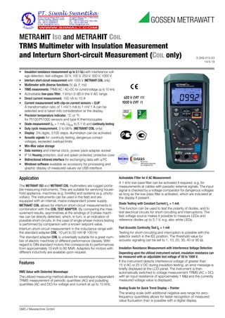
- 1. 3-349-415-03 14/4.19 GMC-I Messtechnik GmbH METRAHIT ISO and METRAHIT COIL TRMS Multimeter with Insulation Measurement and Interturn Short-circuit Measurement (COIL only) 600 V CAT III 1000 V CAT II Application The METRAHIT ISO and METRAHIT COIL multimeters are rugged porta- ble measuring instruments. They are suitable for servicing house- hold appliance, machines (e.g. forklifts) and systems (e.g. photo- voltaic). The instruments can be used in the field and are equipped with an internal, mains-independent power supply. METRAHIT COIL allows for interturn short-circuit measurements in combination with the COIL TEST ADAPTER. By comparing the mea- surement results, asymmetries at the windings of 3-phase machi- nes can be directly detected, which, in turn, is an indication of possible short-circuits. In the case of single-phase motors testing is performed by comparison with a known setpoint value. Interturn short-circuit measurement in the inductance range with the standard adapter COIL: 10 μH to 50 mH @ 100 Hz The standard adapter COIL is universially suitable for a great num- ber of electric machines of different performance classes. With regard to DIN standard motors this corresponds to performances from approximately 15 kVA to 80 MVA. Adapters for motors with different inductivity are available upon request. Features RMS Value with Distorted Waveshape The utilized measuring method allows for waveshape independent TRMS measurement of periodic quantities (AC) and pulsating quantities (AC and DC) for voltage and current at up to 10 kHz. Activatable Filter for V AC Measurement A 1 kHz low-pass filter can be activated if required, e.g. for measurements at cables with parasitic external signals. The input signal is checked by a voltage comparator for dangerous voltages as long as the low-pass filter is activated, which are indicated at the display if present. Diode Testing with Constant Current Ic = 1 mA This function can be used to test the polarity of diodes, and to test electrical circuits for short-circuiting and interruptions. The test voltage source makes it possible to measure LEDs and reference diodes up to 5.1 V, e.g. also white LEDs. Fast Acoustic Continuity Test Ik = 1 mA Testing for short-circuiting and interruption is possible with the selector switch in the position. The threshold value for acoustic signaling can be set to 1, 10, 20, 30, 40 or 90 Ω. Insulation Resistance Measurement with Interference Voltage Detection Depending upon the utilized instrument variant, insulation resistance can be measured with an adjustable test voltage of 50 to 1000 V. If the instrument detects interference voltage of greater than 15 V AC or 25 V DC during insulation testing, an error message is briefly displayed at the LCD panel. The instrument is then automatically switched to voltage measurement TRMS (AC + DC) with an input resistance of approximately 1 MΩ and the currently measured voltage value is displayed. Analog Scale for Quick Trend Display – Pointer The analog scale (with additional negative axis range for zero- frequency quantities) allows for faster recognition of measured value fluctuation than is possible with a digital display. • Insulation resistance measurement up to 3.1 GΩ with interference volt- age detection, test voltages: 50 V, 100 V, 250 V, 500 V, 1000 V • Interturn short-circuit measurement with 1000 V (METRAHIT COIL only) • Multimeter with diverse functions (V, Ω, F, Hz) • TRMS measurements: TRMS AC / AC+DC for current/voltage up to 10 kHz • Activatable low-pass filter, 1 kHz/–3 dB in the V AC range • Direct current measurement, 100 nA to 10 A • Current measurement with clip-on current sensors – CLIP A transformation ratio of 1 mV:1 mA to 1 mV:1 A can be selected and is taken into consideration at the display. • Precision temperature indicator, °C or °F, for Pt100/Pt1000 sensors and type K thermocouples • Diode measurement (IK = 1 mA, Uflow to 5.1 V) and continuity testing • Duty cycle measurement, 5 to 95% (METRAHIT COIL only) • Display: 3¾ digits, 3100 steps, illumination can be activated • Acoustic signals for: continuity testing, dangerous contact voltages, exceeded overload limits • Min-Max value storage • Data memory and internal clock, power pack adapter socket • IP 54 Housing protection, dust and splash protected, protective cover • Bidirectional infrared interface for exchanging data with a PC • Windows software available as accessory for processing and graphic display of measured values via USB interface
- 2. 2 GMC-I Messtechnik GmbH METRAHIT ISO and METRAHIT COIL TRMS Multimeter with Insulation Measurement and Interturn Short-circuit Measurement (COIL only) Automatic/Manual Measuring Range Selection Measured quantities are selected with the rotary switch. The mea- suring range can be automatically matched to the measured value, or selected manually. High Resolution Mode Via mem function „Set Resol“, the multimeter (in V DC and Ohm- function) can be switched to a high-resolution operating mode with 30,000 digits and enhanced accuracy. Automatic Storage of Measured Values The DATA HOLD function automates the storage of measured val- ues after they have settled in. A patented process assures that random values are not saved to memory in the case of rapidly changing measured quantities, but rather the actual measured value. The stored measured value appears at the digital display. The analog display continues to read out the current measured value. Overload Protection Overload protection safeguards the instrument in all measuring functions against voltage of up to 1000 V. Voltages of greater than 1000 V and currents of greater than 10 A are indicated acousti- cally. FUSE appears at the display if the fuse for the current mea- suring input blows. Battery Charging Status – Power Saving Circuit The battery charging status is indicated by means of four symbols. The device is switched off automatically if the measured value remains unchanged for a period of between 10 and 59 minutes (adjustable), and if none of the controls are activated during this time. Automatic shutdown can be deactivated by switching the instrument to continuous operation. Three Connector Jacks with Automatic Blocking Sockets (ABS) * All current ranges are implemented via a single connector jack which prevents any possibility of operator error. Beyond this, the automatic blocking sockets prevent incorrect connection of the measurement cables, as well as selection of the wrong measured quantity. Danger to the user, the instrument and the device under test resulting from operator error is thus ruled out. * Patented (patent no. EP 1801 598 and US 7,439,725) Housing and Protective Cover for Harsh Conditions • New housing design • Separate battery and fuse compartments • Intelligent key functions with SMD button The instrument is protected against damage in the event of impacts or dropping by means of a soft rubber cover with tilt stand and test probe holder. The rubber material also assures that the instrument does not wander if it is set up on a vibrating surface. Infrared Data Interface The device can be remote configured, and momentary and saved measurement data can be read out via the bidirectional infrared interface. The USB⏐ X-TRA interface adapter and METRAwin 10 soft- ware are required to this end (see accessories). Interface protocol and device driver software for LabVIEW® (National Instruments™) are available upon request. Voluntary Manufacturer’s Guarantee 36 months for materials and workmanship 1 to 3 years for calibration (depending upon application) DAkkS calibration certificate METRAHIT ISO cable multimeters are furnished with an internationally valid DAkkS calibration certificate (recognized by EA and ILAC). In addition to standard quantities, our DAkkS calibration lab is also accredited for high value ohmic resistance of up to 30 GΩ / 1000 V. After the specified calibration interval has elapsed (recommended interval: 1 to 3 years), the multimeters can be inexpensively recalibrated at our own DAkkS calibration center. Overview of Features Included 1 For 15,000 measured values, sampling rate adjustable from 0.1 seconds to 9 hours Scope of Delivery 1 Insulation multimeter METRAHIT ISO or METRAHIT COIL 1 Protective rubber cover 1 Pair of safety measurement cables with 4 mm test probes, 1000 V CAT II, 600 V CAT III (KS17-2) 1 DAkkS calibration certificate 2 Batteries, 1.5 V, type AA, installed 1 COIL TEST ADAPTER for interturn short-circuit measurement (only in combination with METRAHIT COIL) 1 Condensed operating instructions*, English/German * Detailed operating instructions are available for download on the Internet at www.gossenmetrawatt.com Function METRAHIT ISO METRAHIT COIL V AC+DC TRMS (Ri = 1 MΩ) • • V AC / Hz TRMS (Ri ≥ 9 MΩ) • filter • filter V AC+DC TRMS (Ri ≥ 9 MΩ) • • V DC (Ri ≥ 9 MΩ) • • Hz (V AC) ... 300 kHz ... 300 kHz Bandwidth, V AC 15 Hz ... 10 kHz 15 Hz ... 10 kHz A AC / Hz TRMS 300 μA 3/30/300 mA 3 A / 10 A 300 μA 3/30/300 mA 3 A / 10 A A AC+DC TRMS A DC Fuses 10 A / 1000 V 10 A/1000 V Transformation Ratio mV/A, mA/A mV/A, mA/A Hz (A AC) ... 30 kHz ... 30 kHz Insulation resistance MΩ@UISO test voltage selectable test voltage selectable Interturn short-circuit measurement MΩCOIL — • Duty cycle measurement % — • Resistance Ω • • Continuity • • Diode ... 5.1 V • • Temperature TC (K) • • Temperature RTD • • Capacitance • • Min-Max / data hold • • 4 MBit memory 1 • • IR Interface • • Power pack socket • • Protection IP 54 IP 54 Measuring category 1000 V CAT II, 600 V CAT III 1000 V CAT II, 600 V CAT III 1 kHz 1kHz
- 3. GMC-I Messtechnik GmbH 3 METRAHIT ISO and METRAHIT COIL TRMS Multimeter with Insulation Measurement and Interturn Short-circuit Measurement (COIL only) Technical Data 1 15 ... 45 ... 65 Hz ... 10 (5) kHz sine. See page 6 regarding influence 2 At 0° ... + 40° C 3 Display of up to max. 5.1 V, “OL” in excess of 5.1 V. 4 Applies to measurements at film capacitors and battery operated 5 Lowest measurable frequency for sinusoidal measuring signals symmetrical to the zero point 6 Overload capacity of the voltage measurement input: power limiting: frequency x voltage max. 3 x 10⁶ V x Hz at > 100 V 7 Overload capacity of the current measurement input: See current measuring ranges for maximum current values. 8 Input sensitivity, sinusoidal signal, 10% to 100% of voltage or current measuring range; limitation: up to 30% of the range at up to 100 kHz in the mV measuring range., 30% of the range in the 3 A measuring range The voltage measuring ranges with max. 30 kHz apply in the A measuring range. 9 Plus sensor deviation 10 With ZERO function active 11 With short circuited terminal tips Exception: residual value of 1 to 10 digits, in the mV/μA range 1 to 35 d at zero point due to the TRMS converter 12 10 minute cool-down period 13 Required signal range 30% to 100% of the voltage measuring range Key: d = digit(s), MR = measuring range, rdg. = reading Meas. Func- tion (input) Measuring Range Resolution at Upper Range Limit Input Impedance Intrinsic Uncertainty under Reference Conditions Overload Capacity 2) ±(... % rdg. + ... d) 30000 3000 3000 3000 30000 3000 ~ / ~1) 11) 1) 11) Value Time V 300.0 mV 10 μV 100 μV 9 MΩ 9 MΩ // < 50 pF 0.15 + 15 10) 0.2 + 310) 1 + 3 (> 100 D) 1.5 + 5 (> 100 D) 1000 V DC AC RMS Sine 6) Cont. 3.000 V 100 μV 1 mV 9 MΩ 9 MΩ // < 50 pF 0.15 + 15 0.15 + 2 1 + 3 (> 30 D) 1.5 + 5 (> 100 D) 30.00 V 1 mV 10 mV 9 MΩ 9 MΩ // < 50 pF 0.15 + 15 0.15 + 2 300.0 V 10 mV 100 mV 9 MΩ 9 MΩ // < 50 pF 0.15 + 15 0.15 + 2 1000 V 100 mV 1 V 9 MΩ 9 MΩ // < 50 pF 0.15 + 15 0.2 + 2 Voltage drop at approx. range limit ~1) 11) 1) 11) A 300.0 μA 100 nA 18 mV 18 mV 0.5 + 5 1.5 + 5 (> 100 D) 1.5 + 5 (> 100 D) 0.3 A Cont. 3.000 mA 1 μA 160 mV 160 mV 0.2 + 3 1.5 + 5 (> 30 D) 1.5 + 5 (> 100 D) 30.00 mA 10 μA 32 mV 32 mV 0.5 + 3 300.0 mA 100 μA 200 mV 200 mV 0.2 + 3 3.000 A 1 mA 120 mV 120 mV 1 + 5 10 A 5 min 12) 10.00 A 10 mA 400 mV 400 mV 1 + 5 Factor 1:1/10/100/1000 Input Input impedance ~1) 11) 1) 11) A @ A 0.03/0.3/3/30 A 30 mA Current measurement input (jack A~) — 1.5 + 5 (> 100 D) — 0.3 A Cont. 0.3/3/30/300 A 300 mA 3/30/300/3k A 3 A Plus clip-on current transformer error 3 A 5 min A @ V 0.3/3/30/300 A 300 mV Voltage measurement input approx. 9 MΩ ( V socket) 0.5 + 3 1.5 + 3 (> 300 D) 1.5 + 5 (> 300 D) Meas. input 6): 3/30/300/3k A 3 V 1.5 + 3 (> 30 D) 1.5 + 5 (> 100 D) 1000 V RMS max. 10 s 30/300/3k/30k A 30 V Plus clip-on current sensor error Open-circuit voltage Meas. current at range limit ±(... % rdg. + ... d) 30000 3000 Ω 300.0 Ω 10 mΩ 100 mΩ < 1.4 V Approx. 300 μA 0.5 + 15 with ZERO active 0.5 + 3 with ZERO active 1000 V DC AC RMS Sine max. 10 s 3.000 kΩ 100 mΩ 1 Ω < 1.4 V Approx. 200 μA 0.5 + 15 0.5 + 2 30.00 kΩ 1 Ω 10 Ω < 1.4 V Approx. 30 μA 0.5 + 15 0.5 + 2 300.0 kΩ 10 Ω 100 Ω < 1.4 V Approx. 3 μA 0.5 + 15 0.5 + 2 3.000 MΩ 100 Ω 1 kΩ < 1.4 V Approx. 0.3 μA 0.5 + 15 0.5 + 2 30.00 MΩ 1 kΩ 10 kΩ < 1.4 V Approx. 33 nA 2.0 + 20 2.0 + 5 300.0 Ω 100 mΩ ca. 10 V Approx. 1 mA const. 3 + 5 5.1 V 3) 1 mV ca. 10 V 2 + 5 Discharge resist. U0 max ±(... % rdg. + ... d) F 30.00 nF 10 pF 10 MΩ 0.7 V 1 + 6 4) with ZERO function active 1000 V DC AC RMS Sine max. 10 s 300.0 nF 100 pF 1 MΩ 0.7 V 1 + 6 4) 3.000 μF 1 nF 100 kΩ 0.7 V 1 + 6 4) 30.00 μF 10 nF 12 kΩ 0.7 V 1 + 6 4) 300.0 μF 100 nF 3 kΩ 0.7 V 5 + 6 4) fmin 5) ±(... % rdg. + ... d) Hz (V)/ Hz (A) Hz(A ) 300.0 Hz 0.1 Hz 1 Hz 0.1 + 2 8) Hz (V) 6): Hz(A )6) : 1000 V Hz (A): 7) max. 10 s 3.000 kHz 1 Hz 30.00 kHz 10 Hz 10 Hz Hz (V) 300.0 kHz 100 Hz 100 Hz Resolution Voltage MR 13) Frequency MR ±(... % MR + ... d) % 2.0 .... 98.0 0.1 % 3 V 15 Hz ... 1 kHz 0.2% MR + 8 d 1000 V DC AC RMS Sine 6) Cont. 10.0...90.0 1 kHz ... 4 kHz 0.2% MR/kHz + 8 d 5.0 .... 95.0 30 V 15 Hz ... 1 kHz 0.2% MR + 8 d 10.0...90.0 1 kHz ... 4 kHz 0.2% MR/kHz + 8 d 300 V & 1000 V possible, but not specified ±(... % rdg. + ... d) 9) °C Pt 100 – 200.0 ... +850.0 °C 0.1 °C 0.5 %+ 15 1000 V DC/AC RMS Sine max. 10 sPt 1000 – 150.0 ... +850.0 °C 0.5 %+ 15 K (NiCr-Ni) – 250.0 ... +1372.0 °C 1% + 5 K
- 4. 4 GMC-I Messtechnik GmbH METRAHIT ISO and METRAHIT COIL TRMS Multimeter with Insulation Measurement and Interturn Short-circuit Measurement (COIL only) Insulation Resistance Measurement 1 1 During insulation resistance measurement (MΩ@UISO): If ERROR is displayed >> limits: Uinterference > 10 ... 20 V and Uinterference ≠ UISO, Ri < 50 kΩ @ Uiso 50 V, Ri < 100 kΩ @ Uiso 100 V, Ri < 250 kΩ @ Uiso 250 V, Ri < 500 kΩ @ Uiso 500 V, Ri < 1000 kΩ @ Uiso 1000 V 2 Interference voltage measurement TRMS (V AC + DC) with 1 MΩ input resistance, Bandwidth 15 Hz ... 500 Hz, measuring error 3% + 30 Digit Interturn Short-circuit Measurement (METRAHIT COIL only) 2) Interference voltage measurement TRMS (V AC + DC) with 1 MΩ input resistance, frequency response width 15 Hz ... 500 Hz, accuracy 3% + 30 digits Interturn short-circuit measurement in the inductance range: 10 μH to 50 mH @ 100 Hz Internal Clock Time format DD.MM.YYYY hh:mm:ss Resolution 0.1 s Accuracy ±1 min./month Temp. Influence 50 ppm/K Reference Conditions Ambient temperature +23 °C ±2 K Relative humidity 40% … 75% Measured qty. frequency 45 Hz … 65 Hz Measured qty. waveshape Sine Battery voltage 3 V ±0.1 V Influencing Quantities and Influence Error 1 With zero balancing 2 Power limiting: frequency x voltage max. 3 x 10⁶ V x Hz 3 The accuracy specification is valid as of a display value of 10% and up to 100% of the measuring range for both measuring modes with the TRMS converter in the A AC and A (AC+DC) ranges. 5 Except for sinusoidal waveshape Measuring Range Resolution Nominal Voltage UISO IntrinsicUncertainty under Reference Conditions ±(% rdg + d) 0.3 V ... 1000 V 2) Ri=1MΩ 3 + 30 > 100 digits 5 ... 310.0 kΩ 0.1 kΩ 50, 100, 250, 500 V 3 + 5 0.280 ... 3.100 MΩ 1 kΩ 50, 100, 250, 500, 1000 V 3 + 5 02.80 ... 31.00 MΩ 10 kΩ 50, 100, 250, 500, 1000 V 5 + 5 028.0 ... 310.0 MΩ 100 kΩ 50, 100, 250, 500, 1000 V 5 + 5 0280 ... 3100 MΩ 1 MΩ 500, 1000 V 5 + 5 Measuring Function Nom. Voltage UN Open- Circuit Voltage Uo Nom. Cur- rent IN Short- Circuit Cur- rent Ik Acoustic Signal for Overload Capacity Value Time Uinterference/ MΩ@UISO — — — — U > 1000 V 1000 V Cont. MΩ@UISO 50, 100, 250, 500 V Max. 1.2x UIso 1.0 mA < 1.2 mA U > 1000 V 1000 V 10 s MΩ@UISO 1000 V Max. 1.1x UIso 0.5 mA < 1.2 mA U > 1000 V 1000 V 10 s Measuring Range Resolution Nominal Voltage UISO Intrinsic Uncertainty at Reference Conditions ±(% rdg. + d) 0.3 V ... 1000 V 2) Ri=1MΩ 3 + 30 > 100 digits 10.0 ... 30.9 μs 0.1 [μs] 1000 V 10 + 5 digits 31 ... 250 μs 1 [μs] Influencing Quantity Sphere of Influence Measured Quantity / Measuring Range 1 Influence Error (...% rdg. + ... d) / 10 K Temperature 0 °C ... +21° C and +25° C ... +40° C V 0.2 + 5 V 0.4 + 5 300 Ω ... 3 MΩ 0.5 + 5 30 MΩ 1 + 5 mA/A 0.5 + 5 mA/A 0.8 + 5 30 nF ... 300 μF 1 + 5 Hz 0.2 + 5 °C/°F (Pt100/Pt1000) 0.5 + 5 Influ- encing Qty. Measured Quantity / Measuring Range Sphere of Influence Intrinsic uncertainty 3 ±( ... % rdg. + ... d) Fre- quency VAC 2 300 mV ... 300 V > 15 Hz ... 45 Hz 2 + 5 > 300 digits > 65 Hz ... 2 kHz 2 + 5 > 300 digits > 2 kHz ... 10 kHz 3 + 5 > 300 digits 1000 V > 65 Hz ... 5 kHz 3 + 5 > 60 digits AAC 300 μA ... 10 A > 15 Hz ... 45 Hz 3 + 10 > 300 digits > 65 Hz ... 10 kHz AAC +DC 300 μA ... 10 A > 15 Hz ... 45 Hz 3 + 30 > 300 digits > 65 Hz ... 10 kHz AAC 300 mV / 3 V / 30 V2 >65 Hz ... 10 kHz 3 + 5 > 300 digits AAC 30 mA / 300 mA 3 A >65 Hz ... 10 kHz 3 + 30 > 300 digits Influencing Quantity Sphere of Influence Measured Quantity / Measuring Range Influence Error 5 Crest factor CF 1 ... 3 V , A ± 1% rdg. > 3 ... 5 ± 3% rdg. Influencing Quantity Sphere of Influence Measured Quantity Influence Error Relative Humidity 75%, 3 days, instrument off V, A, Ω, F, Hz, °C 1 x intrinsic uncertainty Battery voltage 2.0 to 3.6 V ditto Included in intrinsic uncer- tainty Influencing Quantity Sphere of Influence Measured Qty. / Measuring Range Damping Common Mode Interference Voltage Interference quantity max. 1000 V V > 120 dB Interference quantity max. 1000 V 50 Hz ... 60 Hz, sine 3 V , 30 V > 80 dB 300 V > 70 dB 1000 V > 60 dB Series Mode Interference Voltage Interference quantity: V , respective nominal value of the measuring range, max. 1000 V , 50 Hz ... 60 Hz sine V > 50 dB Interference quantity max. 1000 V V > 110 dB
- 5. GMC-I Messtechnik GmbH 5 METRAHIT ISO and METRAHIT COIL TRMS Multimeter with Insulation Measurement and Interturn Short-circuit Measurement (COIL only) Response Time (after manual range selection) Display LCD panel (65 mm x 36 mm) with analog and digital display including unit of measure, type of current and various special functions Background Illumination Background illumination is switched off approximately 1 minute after it has been activated. Analog Display LCD scale with pointer Scaling Linear: 5 ... 0 ... ±30 with 35 scale divisions for , 0 ... 30 with 30 scale divisions in all other ranges Polarity display with automatic switching Overflow display with the symbol Measuring rate 40 measurements per second and display refresh Digital Display / char. height 7-segment characters / 15 mm Number of places 3¾ digits 3100 steps, the changeover function to 4¾ digits in measuring function V DC and Ω depends on parameter selection Overflow display “OL” is displayed for ≥ 30000 digits, or ≥ 3100 digits, respectively Polarity display “–” (minus sign) is displayed if plus pole is connected to “⊥” Measuring rate 10 and 40 measurements per second with the Min-Max function except for the capacitance, frequency and duty cycle measuring functions Refresh rate 2 times per second, every 500 ms Electrical Safety Safety class II per DIN EN 61010-1:2011/VDE 0411- 1:2011 Measuring category CAT II CAT III Nominal voltage 1000 V 600 V Pollution degree 2 Test voltage 5.2 kV~ per DIN EN 61010-1:2011/ VDE 0411-1:2011 Fuses Fuse link FF 10 A / 1000 V AC/DC; 10 x 38 mm; Switching capacity: 30 kA at 1000 V AC/DC, protects the current measurement input in the 300 μA through 10 A ranges Power Supply Battery 2 ea. 1.5 V mignon cell (2 ea. size AA), alkaline manganese per IEC LR6 Service life With alkaline manganese batteries: approx. 200 hours (without MΩISO measurement) Battery test Battery capacity display with battery sym- bol in 4 segments: „ “. Querying of momentary battery voltage via menu function. Power OFF function The multimeter is switched off automatically: – If battery voltage drops to below approx. 2.0 V – If none of the keys or the rotary switch are activated for an adjustable duration (10 to 59 min.) and the multimeter is not in the continuous operation mode Power pack socket If the power pack has been plugged into the instrument, the installed batteries are disconnected automatically. Rechargeable batteries can only be recharged externally. 1 Times 0.7 for interface operation Electromagnetic Compatibility (EMC) Interference emission EN 61326-1:2013, class B Interference immunity EN 61326-1:2013 EN 61326-2-1:2013 Ambient Conditions Accuracy range 0 °C ... +40 °C Operating temp. range −10 °C ... +50 °C Storage temp. range −25 °C ... +70 °C (without batteries) Relative humidity 40 to 75%, no condensation allowed Elevation to 2000 m Deployment Indoors, except within specified ambient conditions Measured Quantity / Measuring Range Response Time, Digital Display Jump Function of the Measured Quantity V , V A , A 1.5 s From 0 to 80% of upper range limit value 300 Ω ... 3 MΩ 2 s From ∞ to 50% of upper range limit value 30 MΩ, MΩ@UISO Max. 5 s Continuity < 50 ms °C (Pt 100) Max. 3 s 1.5 s 30 nF ... 300 μF Max. 5 s From 0 to 50% of upper range limit value>10 Hz 1.5 s Measuring Function Nominal Voltage UN Resistance of the DUT Service Life in Hours Number of Possible Measurements with Nominal Current per VDE 0413 V 200 1 V 150 1 MΩ @UISO 100 V 1 MΩ 50 100 V 100 kΩ 3000 500 V 500 kΩ 600 1000 V 2 MΩ 200
- 6. 6 GMC-I Messtechnik GmbH METRAHIT ISO and METRAHIT COIL TRMS Multimeter with Insulation Measurement and Interturn Short-circuit Measurement (COIL only) Data Interface Type Optical via infrared light through the housing Data transmission Serial, bidirectional (not IrDa compatible) Protocol Device-specific Baud rate 38,400 baud Functions – Select/query measuring functions and parameters – Query momentary measurement data The USB⏐ X-TRA plug-in interface adapter (see accessories) is used for adaptation to the PC’s USB port. Internal Measured Value Storage Memory capacity 4 MBit / 540 kB for approx. 15,000 measured values with indication of date and time Mechanical Design Housing Impact resistant plastic (ABS) Dimensions 200 x 87 x 45 mm (without protective rubber cover) Weight Approx. 0.35 kg with batteries Protection Housing: IP 54 (pressure equalization by means of the housing) Table Excerpt Regarding Significance of IP Codes Applicable Regulations and Standards Accessories for operation at a PC Interface Adapter for USB Connection The USB⏐ X-TRA bidirectional interface adapter includes the following functions: • Configure the METRAHIT ISO from a PC. • Transmit live measurement data to the PC. • Read data out of memory from the METRAHIT ISO. The adapter does not require a separate power supply. Its baud rate is 38,400 baud. A CD ROM is included which contains current drivers for Windows operating systems.⏐ METRAHIT COIL with COIL TEST ADAPTER IP XY (1st char. X) Protection against pene- tration by solid particles IP XY (2nd char. Y) Protection against penetration by water 0 Not protected 0 Not protected 1 ≥ 50.0 mm dia. 1 Vertical dripping 2 ≥ 12.5 mm dia. 2 Dripping (15° inclination) 3 ≥ 2.5 mm dia. 3 Spray water 4 ≥ 1.0 mm dia. 4 Splashing water 5 Dust protected 5 Jet-water DIN EN 61010, part 1:2001/VDE 0411-1:2002 Safety requirements for electrical equipment for measurement, control and laboratory use DIN EN 61326-1 VDE 0843-20-1 Electrical equipment for measurement, control and laboratory use – EMC requirements – Part 1: General requirements EN 60529 VDE 0470, part 1 Test instruments and test procedures – degrees of protection provided by enclosures (IP code)
- 7. GMC-I Messtechnik GmbH 7 METRAHIT ISO and METRAHIT COIL TRMS Multimeter with Insulation Measurement and Interturn Short-circuit Measurement (COIL only) Order Information 1) with safety cap applied 2) without safety cap applied For additional information regarding accessories please refer to • Measuring Instruments and Testers catalog • www.gossenmetrawatt.com Designation Type Article Number Insulation multimeter See selection list or scope of delivery on page 2 for scope of delivery. METRAHIT ISO M246B Insulation multimeter with interturn short- circuit measurement, for standard equip- ment see Selection List or Scope of Delivery on page 2 METRAHIT COIL M246C Power pack: 90 ... 250 V AC / 5 V DC, 600 V CAT IV NA⏐ X-TRA Z218G Accessory Cables and Adapters Cable set (1 pair of measurement cables), 1.2 m, with VDE-GS mark 600 V CAT IV 1 A 1) , 1000 V CAT III 1 A 1) 1000 V CAT II 16 A 2) KS17-2 GTY3620034P0002 Cable set with 2 mm ∅ steel tips with cable length 120 cm, 1000 V/CAT II KS17-S Z110H Cable set incl. test probes, clips and USA test probes, (1000 V CAT II / III 20 A) KS-NTS Z110W Cable set for telecommunication application (a-b-E) 1000 V CAT III 1 A 1) KS21-T Z110U Alligator clips (1 pair) for KS17-2 1000 V CAT III 16 A KY95-3 Z110J Clip-on current sensor, 10 mA … 100 A, 1 mV / 10 mA, clip opening: 15 mm dia. WZ12B Z219B Accessories for Operation at a PC Bidirectional interface adapter, IR-USB USB⏐ X-TRA Z216C METRAwin 10 software METRAwin 10 GTZ3240000R0001 Accessories for Temperature Measurement with Resistance Thermometer Pt100 temperature sensor for surface and emersion measurements, -40 … +600 °C Z3409 GTZ3409000R0001 Pt1000 temperature sensor for measure- ment in gases and liquids, -50 … +220° C (for servicing household appliances) TF220 Z102A Pt100 oven sensor, -50 … +550 °C TF550 GTZ3408000R0001 Ten adhesive Pt100 temperature sensors, -50 … +550 °C TS Chipset GTZ3406000R0001 Protection and Transport Accessories Imitation leather carrying pouch F829 GTZ3301000R0003 Cordura belt pouch HitBag Z115A Ever-ready case for 2 instruments and accessories F840 GTZ3302001R0001 Hard case for one instrument and accessories HC20 Z113A Hard case for two instruments and accessories HC30 Z113A Replacement Fuses Fuses (pack of 10) FF 10 A/ 1000 V AC/DC Z109L
- 8. METRAHIT ISO and METRAHIT COIL TRMS Multimeter with Insulation Measurement and Interturn Short-circuit Measurement (COIL only) Edited in Germany • Subject to change without notice • A pdf version is available on the Internet GMC-I Messtechnik GmbH Südwestpark 15 90449 Nürnberg • Germany Phone +49 911 8602-111 Fax +49 911 8602-777 E-Mail info@gossenmetrawatt.com www.gossenmetrawatt.com