
Recomendados
Más contenido relacionado
La actualidad más candente
La actualidad más candente (20)
Similar a Machines dc motors
Similar a Machines dc motors (20)
Más de sld1950
Último
Último (20)
Machines dc motors
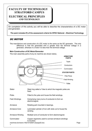
- 1. FACULTY OF TECHNOLOGY FACULTY OF TECHNOLOGY STRATFORD CAMPUS STRATFORD CAMPUS ELECTRICAL PRINCIPLES ELECTRICAL PRINCIPLES AND TECHNOLOGY AND TECHNOLOGY On completion of this activity you will be able to describe the characteristics of a DC motor and generator. The pack includes P1 of the assessment criteria for BTEC National – Electrical Technology DC MOTOR The manufacture and construction of a DC motor is the same as the DC generator. The only difference is that the generated emf is greater than the terminal voltage in a generator, whereas in a motor it is less than the terminal voltage. Main Construction of DC Motor/Generator The main assembly parts of any dc machine are shown below, ARMATURE PARTS Teeth Conductors Commutator STATOR PARTS Pole Piece Field Winding Yoke Stator Steel ring called a Yoke to which the magnetic poles are fixed. Poles Fitted to the yoke and house the field windings. Field Windings Comprising many turns of conductor to form an electromagnet. Armature Rotating part mounted in bearings. Armature Core Laminated cylinder of iron with slots cut to house the winding. Armature Winding Multiple turns of conductor to form electromagnet. Commutator Copper segments used to connect armature windings to brushes. machines-dcmotors-140210102607-phpapp02.doc 1 Page
- 2. Winding Connections There are three main styles of winding connections used in a dc machine’ (i) Shunt wound machines have the field winding connected in parallel with the armature circuit. (ii) Series wound machines have the field winding connected in series with the armature. (iii) Compound wound machines use both series and shunt windings. (i) (ii) (iii) There are two styles of armature windings; i) Wave, providing two parallel paths between brushes irrespective of number of poles. ii) Lap, as many parrallel paths as the machine has poles. Wave wound generators produce high voltage low current output. Lap wound generators produce low voltage high current output. machines-dcmotors-140210102607-phpapp02.doc 2 Page
- 3. LOAD CHARACTERISTICS Shunt Wound Motor In the shunt wound motor the field winding is connected in parallel with the armature therefore the field flux is constant so the speed is constant. Armature reaction weakens the field slightly when under heavy load due to heavy armature current which gives an upward slope to the current / torque curve. Since E ∝ Φn , if the flux is constant then n ∝ E , therefore as armature current and volt drop increase, the speed will reduce, thus the speed / torque curve droops. Separately excited shunt motors are used where a steady speed is required. Shunt Field Armature Circuit DC SUPPLY I/T speed N and current I N/T 0 machines-dcmotors-140210102607-phpapp02.doc 3 torque T Page
- 4. Series Wound Motor In the series wound motor the field winding is connected in series with the armature across the supply therefore the field current is also the armature current. On no-load the current is small therefore the machine speed will be high. As the load increases the current and flux will increase and so the speed will reduce. Armature Circuit DC Supply I/T speed N and current I N/T 0 torque T This characteristic provides a high torque at low speeds and is therefore ideal for electric vehicles, trains and starter motors. Series motors are also used to drive fixed loads such as fans. The load must not be removed as the load current and hence flux will reduce causing the speed to increase to a very high level. This will cause permanent damage to the motor due to large centrifugal forces on the armature windings. machines-dcmotors-140210102607-phpapp02.doc 4 Page
- 5. Compound Wound Motor The compound wound motor has both series and shunt field windings. The shunt winding is present to restrict the no-load speed to a safe value, however by varying the number of turns on both the shunt and series windings a combination of characteristics to suite almost any application. There are two types of compound wound motor; Cummulative compound, in which the series winding is so connected that its field assists that of the shunt field. Differential compound, in which the series winding is so connected that its field opposes that of the shunt field. Compound wound motors can be referred to as either ‘long shunt’ or ‘short shunt’ . Shunt Field Shunt Field Armature Circuit Armature Circuit DC Supply DC Supply ‘long shunt’ ‘short shunt’ I/T speed N and current I N/T 0 torque T Compound wound motors are used for heavy industrial duties particularly where sudden heavy load changes can occur such as lifts, pumps, presses conveyors, hoists etc. machines-dcmotors-140210102607-phpapp02.doc 5 Page
- 6. BTEC NATIONAL UNIT 52 - ELECTRICAL TECHNOLOGY ASSIGNMENT No. 1 of 2 – METHODS USED TO PRODUCE ELECTRICITY Date Set: Sept 2007 Set by: Checked by: S Dacey A Gregory To be completed and returned by: November 2007 In order to obtain a PASS grade you must complete the following; Criteria Brief: Describe the characteristics and principles of operation of a DC generator. TASK 1, (P1a). Sketch the circuit diagrams and load characteristics of the three main configurations of DC motor/generator, (Shunt, series and compound). TASK 2, (P1b). Describe the motor principle in terms of force on a current carrying conductor. Criteria Brief: Describe the characteristics and principles of operation of an AC generator, (alternator). TASK 3, (P2a). Sketch the circuit diagrams and load characteristics of wound rotor alternator system, (include excitation windings). TASK 3, (P2b). Plot the AC waveform produced from a rotating vector. machines-dcmotors-140210102607-phpapp02.doc 6 Page
- 7. FURTHER READING BACK EMF (E.M.F. Generated in armature) When the armature in a DC motor rotates its coils cut the field flux generating an emf that opposes the supply, known as back emf. The back emf is equal to the supply voltage V minus the volt drop in the armature circuit. E Back emf, = V − I a Ra = I a × Ra V = E + I a R Armature circuit volt drop, Supply voltage, Back emf, E = V − ( I a × Ra ) Ia Shunt Field A DC Supply Voltage V E Ra KEY TASK A – BACK EMF A DC motor operates from a 220V supply. If the armature resistance is 0.1Ω and armature current is 40A determine the back emf produced. machines-dcmotors-140210102607-phpapp02.doc 7 Page
- 8. DC MOTOR STARTING DC motors produce a starting torque at standstill and are therefore self starting. As we have seen the armature circuit of a DC motor has a very low value of resistance, (tenths of Ohm’s). Assume that we have a DC motor with an armature circuit resistance of 0.1Ω and switched directly to a 250V DC supply. At the instant of switch-on the armature will be at standstill therefore the back emf (E) will be zero. From the emf equation, V = E + IaR Starting current, I = = V −E Ra 250 − 0 = 2500 A 0.1 Such a high starting current would cause damage to the armature and will certainly trip the circuit breaker. To overcome this a resistance must be inserted in the armature circuit to limit the current at startup to a safe value. KEY TASK B - STARTING CURRENT A 15KW DC motor operates from a 440V supply and has an armature circuit resistance of 0.25 ohm. Determine a) the running current of the machine and b) the starting current. Comment on your results. machines-dcmotors-140210102607-phpapp02.doc 8 Page
- 9. KEY TASK C – RUNNING CURRENT A 2.5KW dc shunt wound motor operates from a 250V supply and draws a current of 14A at full load. If the armature resistance is 0.4 ohm and the field resistance is 160 ohms determine a) the armature current and b) the back emf. Comment on your results and the effect of back emf on the running current. machines-dcmotors-140210102607-phpapp02.doc 9 Page
- 10. FACE PLATE STARTER The basic face plate starter consists of a tapped resistance and a spring loaded operating handle. At startup the handle is in the off position and the full resistance is in series with the armature. As the handle is moved across the face of the starter the resistance is taken out of circuit. The handle must be moved gradually to let the motor pick up speed to allow an increase in back emf which in turn will limit the armature current. machines-dcmotors-140210102607-phpapp02.doc 10 Page
- 11. R2 R3 R4 R1 On Off Spring loaded Operating Handle No Volt Coil A Z DC Supply Overload coil Protection Circuits ‘No Volt’ coil is energised by the field current and forms an electro magnet this ‘holds-in’ the spring loaded handle under normal operation once in the ‘On’ position. If there is a loss of field current then the magnetic flux will cease and the spring will return the operating handle to the ‘Off’ position. In the case of an overload situation the high current will cause sufficient flux in the ‘Overload coil’ to short the supply to the no-volt coil and reducing its flux to zero hence releasing the operating handle to the ‘Off’ position. KEY TASK D – FACEPLATE STARTER A 10kW DC motor has an armature resistance of 0.1Ω and is connected to 100V DC supply. Determine a) the direct on-line starting current, b) the series starting resistance required to limit the start current to twice the rated running value. machines-dcmotors-140210102607-phpapp02.doc 11 Page
- 12. SPEED CONTROL OF A DC MOTOR Field Rheostat machines-dcmotors-140210102607-phpapp02.doc 12 Page
- 13. If a variable resistance is connected in series with the shunt field of a DC motor the field current, and hence magnetic flux can be varied by variation of the resistance. This resistance is called a field rheostat. The speed of a DC motor is inversely proportional to the field flux, thus variation of field current will act as a speed control for the motor. IF IA Field Rheostat M DC Supply Shunt Field Divertor Resistance In a series motor it is not practical to connect a resistance in series with the field due to the high current of this circuit and the adverse effect on torque. Two methods of field control are possible with the series motor, 1. 2. Use a shunt-connected resistance called a divertor. Use a tapped field. The divertor resistance is used to carry part of the field current, variation of this resistance controls the field flux hence motor speed. The lower the field flux the higher is the armature speed. DC Supply ID IF IA Divertor Divertor in parallel with Series Field By using a tapped field and varrying the number of turns in the field winding we can varry the ampere-turns which in turn varies the field flux and hence the motor speed. machines-dcmotors-140210102607-phpapp02.doc 13 Page
- 14. DC Supply IA Tapped Series Field Shunt Wound The speed of a shunt wound motor n ∝ V − I a Ra Φ The speed of a shunt wound motor can be varied either by variation of the field flux or armature resistance. Variation of the field flux is achieved by using a variable resistance (shunt regulator or rheostat) connected in series with the field winding. As the resistance is increased the field current and hence the flux is decreased resulting in a speed increase. Series Wound Speed control of a series wound motor is achieved by a) field resistance or b) armature resistance. The speed of a series wound motor is given by; n=k V − I a Ra Φ where k is a constant. Thus a reduction in flux causes an increase in speed. This is achieved by connecting a variable resistance in parallel with the field winding thereby reducing the field current / flux hence increasing the speed. The parallel resistance is known as a diverter. ARMATURE REACTION machines-dcmotors-140210102607-phpapp02.doc 14 Page
- 15. Armature reaction is the effect that the magnetic field produced by the armature current has on the magnetic field produced by the field system. In a generator armature reaction results in a reduction of output voltage and in a motor armature reaction results in increased speed. Fitting compensating windings into the pole faces can overcome this effect. Brush Position The effect of armature reaction is poor commutation resulting in sparking at the brushes. To overcome this effect the brush position is set against the direction of rotation in a motor and with the direction of rotation in a generator. The natural position of the brushes is at 90° to the main field and is known as the “magnetic neutral” axis. At this position there is no emf induced into the conductor immediately beneath the brushes. Effect of Armature Reaction on Brush Position a. Magnetic field due to Poles. b. Magnetic field due to Armature. c. Resulting magnetic field. Interpoles Armature current depends on the load therefore the amount of distortion due to armature reaction is variable. Since it is not possible to alter the brush position as the load changes a set of poles are placed between the main poles called INTERPOLES and connected in series with the armature. The magnetic effect of the interpoles is to reduced the distortion of the field and improve commutation. machines-dcmotors-140210102607-phpapp02.doc 15 Page
- 16. Brushes Brushes are used to provide an electrical connection to the rotating part of the motor, Armature in a DC machine or Wound Rotor in an AC machine. The brushes must, 1. Maintain an uninterruptable contact with the commutator or slip rings. 2. Carry the full load current. 3. Have a wear rate that does not wear the commutator or slip rings. Brush Materials There are many grades of brush but they all fall into the categories listed below, HARD CARBON Having a high co-efficient of friction this material has a tendency to wear the mica insulation and copper commutator. They are mechanically robust and long lasting but their low electrical and thermal conductivity restricts their use to moderate speed low current machines. Some incorporate a proportion of graphite to assist in lubrication. NATURAL GRAPHITE A soft material having good natural lubricating properties and a co-efficient of friction less than carbon. Brushes made of this material are silent running have long life and are suitable for high speed machines. ELECTRO-GRAPHITE Electro-Graphite is formed from carbon by heating in an electrical furnace producing a brush which is soft but very tough. Having a low co-efficient of friction and high current carrying capabilty this material is suitable for severe operating conditions, ie high running speed, heavy overloads and mechanical shock. METAL-GRAPHITE Metal-Graphite is a combination of copper and graphite in varrying proportions. The graphite reduces the rate of wear and the copper providing increased mechanical strength. Having a low co-efficient of friction and low electrical resistance this material is used for low voltage high current DC machines, ie engine starter motors, vehicle electric motors and switch gear contacts. machines-dcmotors-140210102607-phpapp02.doc 16 Page
- 17. Shunt Wound Motor Example. A 500V shunt wound motor has a field winding resistance of 300Ω and an armature resistance of 0.4Ω. If the current taken from the supply is 30A calculate the back emf produced by the armature. 30A IF 500V M IA 300Ω RA=0.4Ω I = I A + IF ∴ I A = I − IF and IF = ∴ I A = 30 −1.66 = 28.4 A V 500 = = 1 .6 A RF 300 E = V − I A RA = 500 − (28.33 × 0.4) = 500 −11.36 = 488.6 V NOTE: If the back emf equalled the supply voltage then no current would flow in the armature and the motor would not start. machines-dcmotors-140210102607-phpapp02.doc 17 Page
- 18. TORQUE Consider the equation for the DC motor supply voltage V, V = E + IaR If we multiply this equation by the armature current Ia we get the power equation, 2 VI a = EI a + I a R 2 Where the term VIa is the total electrical power supplied to the armature and I a R is the power loss due to armature resistance, the difference between these quantities EI a is therefore mechanical power developed by the armature. If T is the torque in newton metres then the mechanical power developed in watts, Tω = 2πnT and since EI a also describes the mechanical power, then Tω = 2πnT = EI a and torque T= The emf E generated by the armature is, 2π nT = EI a = EI a 2πn E= 2 pΦnZ c 2 pΦ nZ Ia c Hence Torque T= = 2 pΦ nZ Ia 2π nc pΦ Z Ia πc newton metres machines-dcmotors-140210102607-phpapp02.doc 18 Page
- 19. DC GENERATOR DC generators are classified according to the method of excitation; i) Seperately excited, ii) Self excited. A seperately excited generator has its field winding connected to a source supply outside the machine. A self excited generator gets its field supply from the armature of its own machine. ia Termina l Voltage V A Load E Field Winding Ext. Supply Ra When a load is connected across the armature terminals; • Current ia will flow. • Terminal voltage V will be reduced from its open circuit (no load) value due to the p.d. caused by the armature resistance Ra. Terminal Voltage, or generated voltage V = E − ia Ra E = V + i a Ra Example 4. Determine the terminal voltage V of a generator which develops an emf E of 400V and has an on load armature current ia of 25A and armature resistance Ra of 0.4Ω. Terminal Voltage, V = E −ia Ra = 400 −( 25)(0.4) = 400 −10 machines-dcmotors-140210102607-phpapp02.doc 19 = 390 volts Page
- 20. Example 5. A generator having an armature resistance of 1Ω when connected to a 50Ω load develops a current of 12A. Determine a) the terminal voltage V, and b) the generated emf E. a) Terminal voltage, V = ia R L = (12)(50) = 600 volts b) Generated emf, E =V + ia Ra = 600 + (12)(1) = 612 volts Also induced emf, E = B × l ×v where B = flux density, l = length of conductor and v = velocity of conductor. Φ a Also flux density, E = Therefore E = or flux area Φ × l ×v a Since for a given machine both ‘l’ and ‘a’ will be constant and v is the rotational speed in rev/sec, ‘n’. We can say that E ∝ nΦ If the speed is changed fron n1 to n2 and the flux changed from Ф1 to Ф2, then the back emf will change from E1 to E2. Therefore E1 nΦ = 1 1 E2 n2Φ2 machines-dcmotors-140210102607-phpapp02.doc 20 Page