The polyphase induction motor is commonly used in industry due to its simplicity and reliability. It works by inducing currents in the rotor windings via a rotating magnetic field produced by the stator windings. This induces a torque on the rotor causing it to rotate at a slightly lower speed than the rotating field. There are two main types: squirrel-cage motors which have shorted rotor windings, and wound-rotor motors which have external connections to the rotor windings allowing control of starting torque. An equivalent circuit model is used to analyze induction motor performance characteristics such as torque-speed curves.
1. Experiment No. 4
The Polyphase Induction Motor
The polyphase induction motor is the most commonly used industrial motor, finding
application in many situations where speed regulation is not essential. It is simple and
relatively inexpensive, and the absence of sliding contacts in the squirrel-cage machine
reduces maintenance to a minimum. There are two general types of polyphase induction
motors: the squirrel-cage type and the wound-rotor machine. Both motors have an
armature or stator structure similar to that of the alternating current generator, consisting
of a hollow cylinder of laminated sheet steel in which are punched longitudinal slots. A
symmetrical polyphase winding is laid in these slots which, when connected to a suitable
voltage source, produces a travelling MMF wave in the air gap, rotating at a synchronous
speed equal to:
f
RPM sync = 120 p
(1)
where f is the frequency and p the number of poles for which the stator is wound.
The squirrel-cage type of rotor is made up of sheet steel laminations keyed to the
shaft and having slots punched in the periphery. The number of slots in the rotor is never
a multiple of the number in the stator, thereby preventing rotor locking under light load
conditions. The rotor conductors in most machines are made of aluminum alloy either
molded or extruded in place in the slots, with end rings being cast as an integral part of
the structure and connecting all bars at both ends. The air-gap length between rotor and
stator is kept as short as manufacturing tolerances will allow in order to minimize the
magnetizing current necessary for the production of normal air-gap flux. A simple two-
pole, three-phase, squirrel-cage induction motor is diagrammed in Fig. 1.
The wound-rotor induction motor has a rotor similar to that of the squirrel-cage
machine except that the short-circuited squirrel-cage winding is replaced by a three-phase
insulated winding similar to that on the stator. This winding is usually wye-connected
with the terminals brought out to three slip rings on the shaft. Graphite brushes connected
to the slip rings provide external access to the rotor winding which is connected to a
rheostatic controller, the purpose of which is to insert additional resistance in each rotor
phase to improve the starting characteristics.
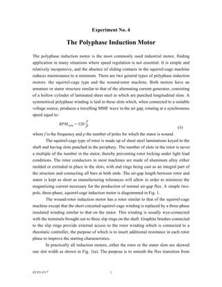
In practically all induction motors, either the rotor or the stator slots are skewed
one slot width as shown in Fig. 1(a). The purpose is to smooth the flux transition from
ECEN 4517 1
2. one slot to the next, thereby reducing harmonics in the torque characteristic and
improving the operation.
(a) (b)
Fig. 1. Physical construction of the squirrel-cage induction motor: (a) cross section
showing stator and rotor, (b) rotor construction.
1. Basic operation of the induction motor
As previously shown, the phase displacement between the voltages applied to the stator
windings produces a travelling MMF or rotating magnetic field in the uniform air gap.
This field links the short-circuited rotor windings, and the relative motion induces short-
circuit currents in them, which move about the rotor in exact synchronism with the
rotating magnetic field. It is well known that any induced current will react in opposition
to the flux linkages producing it, resulting herein a torque on the rotor in the direction of
the rotating field. This torque causes the rotor to revolve so as to reduce the rate of
change of flux linkages reducing the magnitude of the induced current and the rotor
frequency. If the rotor were to revolve at exactly synchronous speed, there would be no
changing flux linkages about the rotor coils and no torque would be produced. However,
the practical motor has friction losses requiring some electromagnetic torque, even at no-
load, and the system will stabilize with the rotor revolving at slightly less than
synchronous speed. A mechanical shaft load will cause the rotor to decelerate, but this
increases the rotor current, automatically increasing the torque produced, and stabilizing
the system at a slightly reduced speed.
The difference in speed between rotor and rotating magnetic field is termed “slip”
which is numerically equal to:
2
3. synchronous speed – rotor speed
Slip = s =
synchronous speed
(2)
This varies from a fraction of one per cent at no-load to a maximum value of three or four
per cent under full load conditions for most properly designed machines. The speed
change between no-load and full-load is so small that the squirrel-cage motor is often
termed a constant-speed machine.
2. Equivalent circuit model
Theoretical analyses of the induction machine consider it to be a transformer with a
rotating secondary. The stator windings constitute primary windings that induce flux in
the rotor and stator iron. The rotor windings constitute a secondary winding that is
shorted. Hence, an equivalent IS Ls Rs LR RR IR'
circuit similar to that +
representing the transformer is VS
Lm Rm 1–s R
derived and appears as in Fig. 2. per phase s R
Since the rotor frequency in the
–
actual machine is dependent
V
V s per phase = LL
upon the rotor speed, all rotor 3
quantities must be modified to Fig. 2. Equivalent circuit model of the induction machine,
be referred to the frequency and per phase.
voltage bases of the stator for
inclusion in the equivalent circuit. Since the circuit represents just one phase of the actual
polyphase machine, all values are given on a per-phase basis.
Once the equivalent circuit constants have been determined, the operating
characteristics may be determined directly from it. The variable load resistance RR (1 –
s)/s models the conversion of power from electrical to mechanical form. The power
absorbed by this resistance is equal to the mechanical output power of the machine Po; for
a three-phase machine, this power is equal to:
21 –s R
Po = 3 I 'R s R
(3)
Similarly, the torque is proportional to the power divided by the speed. Since the speed is
proportional to 1 – s, the torque is given by:
Po 2 RR
T= = 3 I 'R sω
1 – s ωs s
(4)
3
4. Here, ω s is the synchronous speed, in radians per second. The torque is expressed in
Newton-meters. Note that the synchronous speed in rpm is related to the applied stator
frequency f according to Eq. (1). The torque expressed in the English units of foot-pounds
is
2R
T = 3K I 'R sR foot-pounds
(5)
where K = 0.058 p/f.
The losses may be evaluated by realizing that Rs and RR represent stator and rotor
resistances per phase respectively, and that R m models the core loss. For the usual
constant speed application, the mechanical windage (i.e., the resistance of air to rotation
of the shaft) and bearing friction losses are constant; then Rm can also model these losses,
and the total of these losses is called the stray power loss.
The inductance Lm models the magnetization characteristic of the complete flux
path; this is dominated by the characteristic of the air gap between stator and rotor. A
significant difference between the numerical values of the parameters of the induction
machine vs. the transformer is the relatively low value of Lm (transformers typically do
not contain air gaps and hence exhibit relatively large values of Lm). This low Lm leads to
a substantial magnetizing current that is typically similar in magnitude to the current in
the effective load resistance RR (1 – s)/s at full load. In consequence, induction motors
exhibit relatively low power factors, especially at light load.
3. Measurement of model parameters
The equivalent circuit constants may be evaluated in much the same manner as those of
the transformer. If the shaft coupling is disconnected, the power output will be zero and
the load resistance RR(1 – s)/s approaches infinity. For all practical purposes, the series
constants may be neglected and the shunt constants obtained by measuring the current,
voltage, and power under these conditions where:
Zm = V
3I
2
Rm = V
P
Lm = 1
ω 1 2– 1 2
Zm Rm
(6)
with I = line current, P = total three-phase power, and V = line-to-line voltage.
4
5. If the rotor is blocked so as to prevent rotation and a balanced low-voltage three-
phase source connected to the stator terminals, the load resistance RR(1 – s)/s will reduce
to zero, and the shunt branch may be neglected. Then:
Re = RR + Rs per phase = P2
3I
Ze = V
3I
1
L e = L R + L s = ω Z 2 – R2
e e
(7)
Rs per phase may be determined by passing direct current through any two terminals of
the stator, recording the voltage drop, and dividing the resultant resistance by two. Then
RR = R e – R s. It is usually accurate to assume equal stator and rotor leakage inductances,
so that Ls = LR = Le/2.
4. Practical measurement considerations
Examination of the equivalent circuit of Fig. 2 suggests at least two methods for
evaluating the shaft power output of the induction motor from test data. Since the
currents Is and IR differ but slightly under load conditions, Rs and RR can be combined to
the left of the shunt branch without introducing appreciable inaccuracy. Then the total
copper losses will be:
2 2
Pcu = 3 I s Rs + R R = 3 I s Re
and the power output is:
Po = Pin – Pcu – SP
(8)
where Pin is the total three-phase input power measured at the stator terminals under load
conditions, and SP is the stray power loss. Returning to the original equivalent circuit, the
power applied to the rotor portion is:
2
PR = Pin – SP – 3 I s Rs
Since this is all absorbed in the rotor resistance RR and the load resistance RR(1 – s)/s, the
proportion absorbed in the load is (1 – s) of the total. Therefore:
2
Po = Pin – SP – 3 I s Rs 1 – s
(9)
Theoretically, expressions (8) and (9) should give nearly identical results. From a
practical standpoint, (9) does not require the use of a blocked-rotor test for the evaluation
of Re, but its accuracy is dependent upon the accuracy with which the slip is measured.
Expression (8) is independent of speed, but does require a blocked-rotor test that is
impractical for some types of motors.
5
6. 200
Torque
(N-m) Tmax
No added RR
150
Re dde
a
sis d t
ta o r
nc ot
e or
100
Added RR
for optimum
starting torque
50
0
0 0.2 0.4 0.6 0.8 1.0
Shaft speed
Synchronous speed
Fig. 3. Torque vs. speed characteristics of an induction machine example. Solid line: basic squirrel-
cage machine, or wound-rotor machine with no added rotor resistance. Dashed lines: wound-
rotor machine with added external rotor resistance.
5. Characteristics of the squirrel-cage and wound-rotor machines
Evaluation of the torque for various values of slip and constant applied voltage yields a
characteristic similar to that shown as a solid trace in Fig. 3.
The maximum torque may be evaluated by maximizing the expression: T =
2
3||IR’|| RR/s, and will be found to be independent of rotor resistance. However, the slip at
which maximum torque is produced does vary with rotor resistance as shown by the
dotted characteristics in Fig. 3. Normally the rotor resistance is maintained at as low a
value as possible in order to keep the losses low and the efficiency high. This further
leads to good speed regulation, i.e., small change in speed between no load and full load.
However, the starting torque of the low-resistance squirrel-cage induction motor
is relatively low as seen in Fig. 3. This can be explained in a practical manner by
referring to the equivalent circuit and realizing that since the slip is 1 at start, the rotor
branch impedance is simply RR + jωLR and the power factor is low. This low rotor power
factor is responsible for the low starting torque. By adding the appropriate value of
resistance to the rotor circuit, it is possible to improve the rotor power factor and to
produce maximum torque under starting conditions as shown by the dotted characteristic.
However, if the motor is allowed to run in this condition, both the efficiency and speed
regulation will be poor. The wound rotor is used where high starting torque is necessary
so that additional resistance may be placed in the rotor circuit for improvement of the
starting performance, and then removed as the motor accelerates towards normal
6
7. operating speed. Unfortunately, the wound-rotor machine is more expensive than the
squirrel-cage type, and is therefore not generally used where high starting performance is
not required.
Another advantage of the wound rotor machine is that of limiting the starting
current. The squirrel-cage motor usually draws about seven times rated current for an
instant if started at rated voltage. To reduce the effects of this on the system, a few such
motors are equipped with starting compensators which allow the motors to start at about
one-half rated voltage, and then, after they accelerate to normal speed, apply rated
voltage. The disadvantage is that the torque varies as the square of the applied voltage,
and the use of a starting compensator worsens the already low starting torque. The
wound-rotor machine always starts at rated voltage, and has excellent starting
characteristics.
Although it is possible to vary the speed of the wound rotor machine at a given
torque by varying the external rotor resistance, this method is rarely used because of the
increased rotor losses and lowered efficiency. Sometimes induction motors are equipped
with two or more stator windings by means of which the number of magnetic poles may
be changed. By this means, several normal operating speeds may be obtained without
sacrificing other operating characteristics.
In modern applications requiring variable speed control, a power electronics
system is typically used to convert the fixed 50 Hz or 60 Hz utility ac to a variable
frequency ac that is fed to the stator of a squirrel cage machine. This effective varies the
synchronous speed of the machine, and hence it allows complete control of the rotor
speed. The voltage magnitude must be scaled in proportion to the frequency, to maintain
constant stator flux.
6. Simulation via SPICE
Torque-speed characteristics, such as those of Fig. 3, can be generated by simulation of
the model of Fig. 2 using SPICE. An example of a PSPICE input file is listed in Fig. 4.
For this example, the input line-neutral voltage is 90 Vrms, or 127 V peak. The six-pole
60 Hz induction machine has a synchronous speed of (2π60)(2/6) = 125.6 rad/sec. The
normalized shaft speed is used as a parameter that varies the effective load resistance
RR(1 – s)/s . This shaft speed parameter is defined as
shaft speed
speed = 1 – s =
synchronous speed
(10)
The shaft speed parameter is varied from 0.0001 to 0.9995 in increments of 0.02775. For
each value of this parameter, an ac analysis is performed at 60 Hz, and the results are
7
8. ECEN4517 induction machine model
.param speed=0.97 ; speed = 1-slip
.param R2=0.144
.step PARAM speed 0.0001 0.9995 0.02775
Vin 1 0 ac 127
R1 1 2 0.294
L1 2 3 1.3mH
Lm 3 0 35mH
L2 3 4 0.55mH
R2 4 5 {R2}
Rr 5 0 {R2*speed/(1-speed)}
Vslip slip 0 ac {1-speed} ; have the slip available as v(slip)
.ac lin 1 60 60 ; do ac analysis at 60Hz only
.probe
.end
Fig. 4. PSPICE input file listing, for generation of induction machine torque-speed characteristics.
saved in PROBE format. The voltage source Vslip is numerically equal to the slip, and
is saved so that slip can be employed in numerical calculations in PROBE. To plot the
torque-speed characteristic in PROBE, Eq. (4) is evaluated and is plotted vs. the
parameter speed. The data for Fig. 3 was generated in this manner, by plotting the
following equation:
3*I(Rr)*I(Rr)*0.144/125.6/v(slip) (11)
PROBLEMS
1. A certain three-phase 60 Hz induction machine exhibits the following (per-phase) model
parameters:
RS = 0.20 Ω
LS = 0.23 mH
Rm = 250 Ω
Lm = 35 mH
RR = 0.19 Ω
LR = 2.0 mH
The nameplate includes the following data:
Rated speed 1745 rpm
Rated voltage 230 V
(a) How many poles does this machine have? What is the synchronous speed? What is the
value of the slip at rated speed?
To answer the following questions, simulate this machine using PSPICE, as described in the text.
(b) For operation at rated speed, determine: the torque, the mechanical output power, the
input line current, and the power factor.
(c) Plot the torque-speed curve of this machine.
8
9. 2. A 60 Hz three-phase induction motor can be modeled by the conventional T model discussed in
the text. For small slip s, the series impedances of this model (i.e., the stator and rotor winding
resistances and leakage inductances), as well as the core loss, can be neglected entirely. The
resulting simple model then consists solely of a parallel-connected shunt inductor and resistor as
shown below. You may use this approximation to solve this problem.
per 1–s R
phase: Lm s R
The machine is rated 1160 rpm, 50 hp, 415 V (line-to-line), 70 A.
(a) How many poles does this machine have? What is the slip under rated conditions?
(b) What is the value of RR?
(c) What is the value of Lm?
(d) Find an expression for how the load torque and slip are related.
(e) Find an expression for how the slip and power factor are related. As the load torque goes
to zero, what happens to the power factor?
3. A three-phase induction motor is rated as follows:
873 rpm
480 V
50 hp
60 Hz
The results of blocked-rotor, no-load, and dc stator resistance tests are as follows:
480V 60V 5Vdc
46A 102A 50A
1.6kW 2.8kW
(a) Which data belongs to each test?
(b) Sketch the equivalent circuit for this machine, and label all element values.
(c) How many poles does this machine have? What is synchronous speed?
For part (d), to simplify the algebra, you may ignore the stator series impedances (i.e., set R s = 0
and Ls = 0).
(d) The machine now operates at rated speed and voltage. Determine the values predicted by
your model of (i) the mechanical output power, and (ii) the power factor.
9
10. Experiment 4
Pre-lab assignment
ECEN 4517 / 5017
Polyphase induction motor
1. Read all sections of the text.
2. Do problem 3
3. Read the laboratory procedure
This assignment is due from each student at the beginning of the lab session.
10