VTU Notes for Testing and commissioning of Electrical Equipment Department of Electrical and Electronics Faculty Name: Mrs Veena Bhat Designation: Assistant Professor Subject: Testing and Commissioning of Electrical equipment Semester: VII
Intze Overhead Water Tank Design by Working Stress - IS Method.pdf
Unit 3-4-a
1. SYNCRONOUS MACHINES
Introduction:
Synchronous machines are AC machines that have a field circuit
supplied by an external DC source.
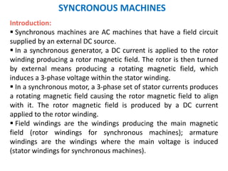
In a synchronous generator, a DC current is applied to the rotor
winding producing a rotor magnetic field. The rotor is then turned
by external means producing a rotating magnetic field, which
induces a 3-phase voltage within the stator winding.
In a synchronous motor, a 3-phase set of stator currents produces
a rotating magnetic field causing the rotor magnetic field to align
with it. The rotor magnetic field is produced by a DC current
applied to the rotor winding.
Field windings are the windings producing the main magnetic
field (rotor windings for synchronous machines); armature
windings are the windings where the main voltage is induced
(stator windings for synchronous machines).
3. Construction of synchronous machines
Two common approaches are used to supply a DC current to the
field circuits on the rotating rotor:
1. Supply the DC power from an
external DC source to the rotor by
means of slip rings and brushes;
2. Supply the DC power from a special
DC power source mounted directly
on the shaft of the machine.
Slip rings are metal rings completely encircling the shaft of a machine
but insulated from it. One end of a DC rotor winding is connected to
each of the two slip rings on the machine’s shaft. Graphite-like
carbon brushes connected to DC terminals ride on each slip ring
supplying DC voltage to field windings regardless the position or
speed of the rotor.
5. Construction of synchronous machines
Slip rings and brushes have certain disadvantages: increased
friction and wear (therefore, needed maintenance), brush
voltage drop can introduce significant power losses. Still this
approach is used in most small synchronous machines.
6. Construction of synchronous machines
On large generators and motors, brushless exciters are used.
A brushless exciter is a small AC generator whose field circuits
are mounted on the stator and armature circuits are mounted on
the rotor shaft.
The exciter generator’s 3-phase output is rectified to DC by a 3-
phase rectifier (mounted on the shaft) and fed into the main DC
field circuit.
It is possible to adjust the field current on the main machine by
controlling the small DC field current of the exciter generator
(located on the stator).
Since no mechanical contact occurs between the rotor and the
stator and exciters of this type require much less maintenance.
7. Construction of synchronous machines
A rotor of large
synchronous machine
with a brushless
exciter mounted on
the same shaft.
Many synchronous
generators having
brushless exciters also
include slip rings and
brushes to provide
emergency source of the
field DC current.
9. SYNCRONOUS MACHINES
SPCIFICATION:
1. Rated Voltage:3.3kV,6.6kV,11kV
2. Power Ratings: 10MW,20MW,50MW,100MW,500MW
3. Excitation Voltage: 100V-1000V dc
4. Excitation Current: 5-20A
5. Speed: in RPM about 3000rpm
6. Cooling System: Forced air, Hydrogen Cooled, Water Cooled
7. Type of Rotor: Salient/Non-Salient
8. Short circuit Ratio: 0.5-1.5
9. Class of insulation
10. Temperature Limits
11. Connections
12. Frequency
10. SYNCRONOUS MACHINES
Technical Specifications:
Sl.No Particulars Turbo generator Hydro Generator
1 Power Rating 60MW,100MW,200MW, 500 MW,
1000MW
5MW,10MW,20MW,50MW,100
MW, 150MW
2 Voltage 11.5kV,13kV,15kV,22kV 6.6kV, 11.5kV
3 Excitation Voltage 425V dc 1000V dc
4 Cooling System Forced Air, Hydrogen & Water
cooled.
Forced Air
5 Rotor Smooth cylindrical Projected pole (salient pole)
6 Speed 3000 rpm,3600rpm 75 rpm, 1000rpm
7 Short circuit ratio 0.5 to 0.6 1.0 to 1.5
8 Excitation
response(rate of
change of exciter
voltage & is
expressed interms
of volt/sec)
0.5 Higher
11. Installation
Physical Inspection:
• Check for damage/missing of parts.
• Machines to be stored in safe place.
Foundation Details:
• Based on type of mounting :horizontal/vertical
• Generally alternators are mounted vertically covering two
floors basement and ground.
• Basic dimension need to be provided by the manufacturer.
• Provided with holes to receive fix bolts securing the bed
plates.
• Holes and anchor bolts should be fixed in the concrete.
12. Foundation Details for ABB synchronous Motor
Foundation design :
The customer is responsible for ensuring that the foundation is dimensioned
correctly. Factors to be taken into consideration include local conditions,
prevailing forces, routing of pipes and cables, and the need to ensure that
service and maintenance can be performed.
13. Steps in Installation of an Alternator
1. Install bedplate with leveling of bed plate.
2. Install bearing pedestals& leveling of the bearing pedestals.
3. Check on stator & rotor.
4. Assembly of the rotor onto the shaft.
5. Installation of the stator.
6. Installing the rotor in the stator.
7. Checking of airgap between stator & rotor.
8. Preparation of shaft coupling.
9. Mounting of shaft coupling on shaft.
10. Preparation of shaft & alignment of shaft.
11. Installation of cooling system
12. Drying out
13. Testing
14. Commissioning.
15. Procedure to start Synchronous Generator
Process is slow and complex and involves:
1. Starting of boiler
2. Turbine auxiliaries
3. Boiler auxiliaries etc.
From cold
1. Starting of boiler auxiliaries
2. Starting of turbine and auxiliaries.
3. Starting of boiler.
4. Roll turbine.
5. Keep the unit as spinning reverse.
16. Excitation System
Should include all equipment required for supply of
field current & voltage regulator system.
Excitation response is in terms of voltage/sec.
Maximum voltage need to be attained by the
exciter at load.
Excitation system provides supply & regulate field
current.
Example: Brushless Excitation system.
17. Excitation System
Necessity :
Source of field current for the excitation of a electrical
machine including its control.
Source can be AC or DC machine and system provide to
regulate or control the amount of field current delivered.
Exciter Ceiling voltage : maximum voltage attained by
an exciter with specified conditions of load.( at rated
speed and specified field temperature).
Exciter Response rate can be increased or decreased
by the exciter voltage.
excitation-system.ppt
18. Brushless Excitation System
Requirement:
Separate AC generator.
Mounted on the motor shaft.
Located at the non-drive end.
Fixed speed motor excitation control & related
protection based on a separate excitation control system.
System also include:
Excitation field application logic.
Minimum & maximum field protection.
Too long start protection.
24. Cooling
Objective : The different methods of cooling of Synchronous machine.
The I2R losses and other losses in electrical machine
appear as heat ,raising the temperature of each
internal part above the ambient temperature of the
surrounding air.
The temperature rise is significant as it affects the
life of the winding insulation.
Heat is removed by a combination of conduction,
convection and by radiation from Outer surfaces.
25. Cooling
Primary coolant: A medium, being at lower temperature
than that part of machine and is in contact with it which
removes the heat.
Secondary coolant: A medium, which being at Lower
temperature than that of primary coolant which removes
the heat given up by primary coolant.
26. Cooling
Heat exchanger: A component of cooling system that
transfers heat from one coolant to another by keeping
the two coolants separate.
Inner cooled (direct cooled) winding: A winding which
has either hollow conductors or tubes which form an
integral part of the winding, through which the coolant
flows.
27. Cooling
Open circuit cooling: A method of cooling in which the
coolant is drawn from the medium surrounding the
machine, passes through the machine and then returns
to the surrounding medium.
Closed circuit cooling: The primary coolant is circulated
in a closed circuit through the machine and if necessary,
through heat exchanges. Heat is transferred to the
secondary coolant.
28. Cooling
Cooling system may be Standby or emergency cooling
system.
Components:
Dependent circulating circuit components
Independent circulating circuit components
Integral circulating circuit components
Machine mounted circulating circuit components
Separately mounted circulating components
Nature of the coolant are designated by, one of the
following letters.
Gases:
Air - A
Hydrogen - H
Nitrogen- N
Carbon dioxide - C
Liquid:
Water – W
Oil - U
29. Cooling
Hydrogen cooling of turbo - generators:
Characteristics of Hydrogen:
• The thermal conductivity of hydrogen is about 7 times
that of air.
•The density of hydrogen is 0.07 times that of air.
•The specific heat of hydrogen is 14 times that of air.
•Hence hydrogen gas is preferred to air as a coolant in
large turbo generators of capacity 60 MW and above.
•It reduces noise and improves heat transfer.
•The hydrogen cooling is direct cooling i.e. the cooling
medium is in direct contact with conductors.
30. Cooling
Hydrogen cooling of turbo - generators:
• The stator conductors are hollow and hydrogen gas
from a separate circuit is circulated through the stator
conductors.
•The pressure of the gas is of the order of 1.5 Kg/m2 and
flow rate is about 15 m3 /sec.
•Hydrogen blowers are required to circulate hydrogen
gas through direct cooled machine.
Advantages :
•Increase efficiency.
•Increase in rating
•Increasing life span
•Less noise.
•Lesser size cooler.
31. Cooling
Water cooled machines:
•In direct water cooling, water is the cooling medium
and it is circulated through stator conductors and rotor
conductors.
•The speed of the water flow in the chillness is about
2.5m/sec
•The water at higher speed, efficiently removes the heat.
34. Types of Enclosure
•The method of cooling is closely related to the
construction and the type of enclosure of the
machine.
Open - pedestal: In this the stator and rotor ends
are open to the outside ambient air, the rotor being
supported on pedestal bearings mounted on the
bed plate.
35. Types of Enclosure
Open end bracket: In this the
bearings forms part of the end
shields which are fixed to the stator
housing. The air is in comparatively
free contact with the stator and
rotor through the openings. This is
common for small and medium size
motors and generators.
36. Types of Enclosure
Protected or end-cover type with guarded openings: The
protector may be screen or fine-mesh over.
37. Types of Enclosure
Drip, splash or hose proof: This is a protected
machine with the openings in the end shield for
cooling. The end shields are designed to prevent entry
of falling water or dirt or jets of liquid.
38. Types of Enclosure
Pipe or duct cooled: With end covers closed except for
flanged openings for connection to cooling pipes.
39. Types of Enclosure
Totally enclosed: The air will not be in contact with the
ambient air. The machine is totally air tight. Total
enclosure may be associated with an internal rotor fan,
an external fan, cooling or closed air circuit cooling in
which the air is circulated to a cooler and returned to the
machine.
41. Types of Enclosure
Flame proof or explosion
proof: This motor is used in
hazardous location such as
mines, chemical industries
etc.
Note: The ratings of machines are dependent upon
their respective cooling systems. For complex
cooling systems, the machines may have to be de-
rated.
42. Duty of Rotating Machines
•The variations of load with time is termed as duty of
motor.
•The duty requirement may be declared numerically
or with the aid of time sequence graphs.
•The duty is very important in case of electrical
motors as they have a time rate of temperature rise.
43. General Requirements and Constructional
Details
• These motors are provided with class E, B or F
insulation.
• For HV motors class F insulation is preferred.
• The rating plate shall be of stainless steel and non
corrosive material.
• In addition to the general parameters of a 3 phase
induction motor, following are to be mentioned:
• Reference to the standard, :IEC, IS and BS standard
specifications
44. Classes of Duty
Following are the classes of duty:
1. S1 – Continuous duty
2. S2 – Short time duty
3. S3 – Intermittent periodic duty
4. S4 – Intermittent periodic duty with starting
5. S5 – Intermittent periodic duty with starting and electric
braking
6. S6 – Continuous duty with intermittent periodic loading
7. S7 – Continuous duty with starting and electric braking
8. S8 – Continuous duty with periodic speed changes
45. Classes of Duty
The symbols for operating duty:
• N - ‘Operation' with normal rated load
• R - Machine at rest and de-energized
• D - Starting duty
• F - Braking duty,
• V - Operation at no load, but rotating
Cyclic duration factor: ratio of operating period
to the total period of a cycle.
46. Classes of Duty
Duty Cyclic duration factor for rotating
machine
S3 N/(N+R)
S4 D+N/(D+N+R)
S5 N+N+F/(D+N+R+F)
S6 N/(N+V)
Cyclic duration factor for different duty
47. Continuous duty (S1)
• Motor is running long enough and temperature
reaches steady value.
• Used in paper mill drives, conveyors, compressors.
48. Short time duty(S2)
• In these motors, the time of operation is very low
and the heating time is much lower than the cooling
time.
• These motors are used in crane drives, drives for
house hold appliances, valve drives etc.
49. Intermittent periodic duty (S3)
• Here the motor operates for some time and then
there is rest period.
• This is seen at press and drilling machine drives.
50. Intermittent periodic duty with starting (S4)
• In this type of duty, there is a period of starting,
which cannot be ignored and there is a heat loss at
that time.
• This motor duty class is widely used in metal cutting
and drilling tool drives, mine hoist etc.
51. Intermittent periodic duty with starting
and braking
• In this type of drives, heat
loss during starting and
braking cannot be ignored.
• The corresponding periods
are starting period,
operating period, braking
period and resting period.
These techniques are used in billet mill drive, manipulator
drive, mine hoist etc.
52. Continuous duty with intermittent
periodic loading
• In this type of motor duty, everything is same
as the periodic duty but here a no load
running period is occurred instead of the rest
period.
• Pressing, cutting are the examples of this
system.
53. Continuous duty with starting and braking
• Consists of periodic cycles each having a period of
starting, a period of running at a constant load and a
period of braking.
• There is no period of rest.
• The main drive of Blooming mill is an example.
54. Continuous duty with periodic speed
changes
• Consists of periodic duty cycle each having a period
of running at one load and speed, and another period
of running at different load and speed.
• There is no period of rest.
• Several paper mill drives are examples.
55. Drying out of synchronous machines
• The insulation of rotating machines is hygroscopic in
nature.
• The moisture absorbed by the insulation is to be removed
by drying till the insulation resistance reaches specified
value.
• The moisture is evaporated from the winding due to
thermal diffusion.
• Moisture gradient depends on temperature gradient within
wet insulation.
• The desired temperature is obtained by heating the
winding.
• During drying it is necessary to record the temperature at
various stages of drying out, insulation resistance and time.
56. Drying out of Synchronous Machines
1. The machine stator
windings are supplied
with low voltage.
2. The input voltage, current,
power & temperature of
winding, temperature
3. of body, temperature of
air are periodically
measured.
4. The end shields of the
machine are removed.
5. The machine body is
covered with tarpaulin. No
cool air blow shall come
over the hot winding.
6.The preparation,
precautions and log book
keeping during
Drying. The machine should
be always attended when
drying out is in progress .
Note: Polarization index to be found .
57. Testing of Synchronous Machines
The tests are conducted to demonstrate that the
machine gives the required performance.
58. Testing of Synchronous Generators
1. Open circuit test (no Load test)
2. Short circuit test
3. Zero Power factor characteristics tests and loss
measurement
4. Temperature rise test by
Full load ZPF over excited run
By equivalent heat run
5. Over speed test
6. High voltage tests
7. Insulation resistance tests
8. Waveform interference, gap length, balance, vibration,
bearing currents, magnetic symmetry etc
9. Measurement of DC resistance of armature and field
windings.
10.Dielectric test
59. Testing of Synchronous Generators
Commissioning test
1. Insulation resistance tests
2. Measurement of DC resistance of armature and field
windings.
3. Waveform interference test
4. Line charging capacity
Performance test
1. Slip test
2. Sudden short circuit test
3. Determination of transient and sub transient parameters
4. Determination of sequence impedance
5. Separation of losses
6. Temperature rise test & retardation test
60. Testing of Synchronous Generators
Factory test
1. Gap length
2. Magnetic symmetry
3. Balancing vibrations &
4. Bearing performance
5. Open circuit test
6. Short circuit test
7. Zero Power factor characteristics tests and loss
measurement
8. Over speed test
9. High voltage tests
10.Waveform interference test, Gap length, Balance,
Vibrations , Bearing currents, Magnetic symmetry etc
11.Dielectric test
61. Testing of Synchronous Motors
1. Measurement of DC resistance of armature and field
windings.
2. Dielectric test on armature and field windings.
3. Mechanical balancing test
4. Temperature rise test
5. Over speed test
6. Harmonic analysis
7. Telephone interference
8. Short circuit test
9. Reactance and time constants
10. Speed torque characteristics
11. Efficiency calculations
12. Bearing insulation test
13. Direction of rotation
14. Current balance on no load
15. Commissioning tests
62. Measurement of Insulation Resistance
•The insulation resistance of
1. stator winding to earthed frame,
2. rotor winding to earthed frame,
3. phase to phase winding pedestal
4. and bearing insulation resistance is measured using
megger.
•The megger readings for 15 seconds and 60 seconds are
taken to find the polarization index.
•The polarization index gives the extent of dryness of the
insulation and is given by
PI= IR60/IR15
63. Measurement of DC winding Resistance
1. Voltmeter ammeter method: Voltage applied
across the winding and current through the winding
are noted at the specified temperature. Then the
resistance is calculated. This method is suitable for
field resistance measurement only.
2. Bridge method: Built in bridges like Wheatstone
bridge and Kelvin's double bridge are used to
measure field resistance & armature resistance
respectively & temperature is also recorded and
three to five readings are taken.
64. Open-circuit test
• The generator is turned at the rated speed
• The terminals are disconnected from all loads, and the field
current is set to zero.
• Then the field current is gradually increased in steps, and the
terminal voltage is measured at each step along the way.
• It is thus possible to obtain an open-circuit characteristic of a
generator ( Voc versus If) from this information
65. Sustained three phase short circuit test
• The synchronous generator
terminals shorted through
ammeters.
• The field current is gradually
increased till the armature
current reaches a maximum
safe value (about 1.5 times
rated current).
• The relation between field current and short circuit
current is drawn and is known as the short circuit
characteristics.
• In sustained short circuit test, the values of field
current and armature current refer to the steady state
values and are measured using indicating meters.
66. Short Circuit Ratio (SCR)
• The short circuit ratio of synchronous machine is
defined as the ratio of field current If OC required to
obtain rated open circuit voltage to the field current
Ifsc required for obtaining rated sustained short
circuit current when running at rated speed.
SCR= Ifoc/Ifsc
• The short circuit ratio is obtained from the data of
no-load test and sustained short circuit test
conducted on the machine.
67. Short Circuit Ratio (SCR)
•The impedance under steady state condition is known
as the synchronous impedance and is defined as the
ratio of field current at rated armature current on
sustained symmetrical short circuit to the field current at
normal open circuit voltage on the air gap line.
•Zs= V rated/Ia rated
•SCR is just the reciprocal of the per unit value of the
saturated synchronous reactance
..
1
_
_
_
upinX
I
I
SCR
sats
IscratedF
VratedF
68. Short Circuit Ratio (SCR)
Significance of SCR:
1. Low value of SCR Xs increases and IaXs drop
increases.
2. Low value of SCR indicates smaller air gap and poor
regulation due to large IaXs drop.
3. Synchronous power is inversely proportional to Xs
which lead lower stability.
69. – then
– If the stator is Y-connected, the per phase stator resistance is
– If the stator is delta-connected, the per phase stator resistance is
DC Test
– The purpose of the DC test is to determine Ra. A variable DC
voltage source is connected between two stator terminals.
– The DC source is adjusted to provide approximately rated
stator current, and the resistance between the two stator
leads is determined from the voltmeter and ammeter
readings DC
DC
DC
V
R
I
2
DC
a
R
R
DCa RR
2
3
70. Determination of Xs
• For a particular field current IfA, the internal voltage Ef (=VA) could
be found from the occ and the short-circuit current flow Isc,A could
be found from the scc.
• Then the synchronous reactance Xs could be obtained using
IfA
Ef or Vt (V) Air-gap line
OCC Isc (A)
SCC
If (A)
Vrated
VA
Isc,B
Isc, A
IfB
scA
fA
unsat,saunsat,s
I
EV
XRZ
22
22
aunsat,sunsat,s RZX
scA
oc,t
scA
f
unsat,s
I
V
I
E
X
: Ra is known from the DC test.
Since Xs,unsat>>Ra,
71. Xs under saturated condition
Ia
Ef Vt=0
jXs Ra
+
+
EfVt=0
jIaXs
IaRa
Ia
scB
frated
sat,sasat,s
I
EV
XRZ
22
At V = Vrated,
22
asat,ssat,s RZX : Ra is known from the DC test.
Equivalent circuit and phasor diagram under condition
IfA
Ef or Vt (V) Air-gap line
OCC Isc (A)
SCC
If (A)
Vrated
VA
Isc,B
Isc, A
IfB
72. Sudden 3-phase short circuit test on generator
When an alternator is subjected to sudden short
circuit, the current in all the three phases increases
suddenly to a high value (10 to 8 time’s full Load
current) during the first quarter cycle.
The flux crossing the air gap is Large during first
couple of cycles.
The reactance during this period is least and the
short circuit current is high.
73. Sudden 3-phase short circuit test on generator
This reactance offered during sub transient period is
called as sub transient reactance Xd".
The first few cycles are covered under sub transient
state.
After few cycles the decrement in rms value of short
circuit current is less rapid than that during the first few
cycles.
74. Sudden 3-phase short circuit test on generator
This state is called as Transient state and the
reactance offered during this period is called as
transient reactance Xd’.
The circuit breaker contacts open during this period.
Finally the transient dies out and the current reaches
a steady sinusoidal state called the steady state and the
reactance offered during this state is called as steady
state reactance Xd.
75. Sudden 3-phase short circuit test on generator
Since the short circuit current lag the voltage by 90°,
the reactance involved is direct axis reactance.
The sudden 3phase short circuit test is conducted at
rated speed and at desired no load voltage.
The 3 phases are shorted suddenly.
To measure the short circuit current storage
oscilloscope with proper probe multiplier is used.
76. Sudden 3-phase short circuit test on generator
The terminal voltages of the machine, the excitation
current and winding temperature are measured just
before the short circuit.
To obtain quantities corresponding to the
unsaturated state of the machine, the test is performed
at several armature voltage of 0.1 to 0.3 pu rated value.
77. Sudden 3-phase short circuit test on generator
To get quantities corresponding to saturated state of
the machine , the test is conducted with rated voltage at
the terminals of the machine before applying short circuit
to the armature winding.
If sudden short circuit test cannot be performed at
rated armature voltage it is recommended that the
test should be conducted at several armature voltages
(eg: 0.3, 0.5 and 0.2 pu of rated armature voltage).
78. Sudden 3-phase short circuit test on generator
To determine the machine quantities, oscillogram is
taken of the armature current in each phase and the
current in the excitation circuit.
Short circuit is initiated by closing the circuit breaker
and is removed by operating the circuit breaker.
79. Sudden 3-phase short circuit test on generator
Oscillogram of current in the phase having
zero dc components
OA,OB,OC are the intercept of X-axis as
shown. Ea=+ve sequence emf/phase -rms
value, the emf induced by the Generator.
The current & reactance are given by the
expressions:
I=OA/=Ea/Xd; Xd=Ea/I;
I’=OB/=Ea/Xd’; Xd’=Ea/I’;
I”=OC/=Ea/Xd”;Xd”=Ea/I”;
(I=Steady I’=Transient I”=Sub-transient
state SC current)
Xd=Direct axis (synchronous)reactance
Xd’=Transient reactance (Direct axis)
Xd”=Sub-transient reactance (direct axis)
80. Negative phase sequence test
• The test is conducted when reduced symmetrical
voltage (0.02-0.2) pu is applied to the machine driven at
rated speed.
• and connected to an external source of supply with
negative phase sequence i.e. operating as an
electromagnetic brake with the slip equal to 2.
• The excitation winding is short circuited.
81. Negative phase sequence test
•If the residual voltage of the machine under test
exceeds 0.30 times of the supply voltage, the rotor
should be demagnetized before testing the machine.
•The voltage and current in all the three phases and
power are noted.
82. Negative phase sequence test
•Negative sequence reactance and resistance are
determined from the negative phase sequence test by
the formulae.
•Procedure for negative sequence reactance.docx
83. Negative phase sequence test
•where P = input power, I = average current measured V
= average voltage measured Lower case letters indicate
per unit values
84. Measurement of sub transient reactance
1. The voltage is applied across any two terminals except neutral,
with the rotor at rest and short circuited on itself through an
ammeter.
2. The rotor is rotated by hand and it will be observed that for a
fixed voltage applied, current in the field varies with the
position of the rotor.
3. When the rotor is in the position of maximum induced field
current direct axis sub transient reactance is obtained.
4. When the rotor is in a position of minimum induced field
current quadrature axis sub transient reactance is obtained
85. Slip test
1. Field terminals of the alternator is kept open.
2. With shunt field rheostat Rh1 in minimum resistance position,
the motor is started using 3-point starter.
3. By adjusting the field rheostat Rh1 of the motor, the alternator
is run at a speed slightly less than the synchronous speed.
4. Now 3- phase AC supply switch is closed, and then applied
voltage of say 40 Volts by varying the autotransformer a
reduced A.C voltage is applied to 3Ф stator winding of the
alternator. By using phase sequence indicator, check the phase
sequence of the alternator.
5. If the phase sequence of the supply is found incorrect,
interchange any two supply lines.
86. Slip test
1. Note down the readings Imin, Imax, Vmin, Vmax from ammeter and
voltmeter respectively.
2. Reduce the autotransformer output to zero.
3. The motor field rheostat is brought to initial position, the DC
supply is switched OFF.
87. ZPF METHOD
1. The O.C and S.C procedures are followed as same in the EMF and MMF
method.
2. By keeping armature rheostat R1 in maximum resistance position, the field
rheostat in R2 minimum resistance position, the DC supply is switched ON
and the motor speed is brought to the rated speed.
3. The open circuit and short circuit procedures are followed as mentioned in
the EMF and MMF method.
4. Now exciter supply is switched ON and exciter current is increased such that
rated voltage is build up across the alternator terminals by varying the knob
of the exciter.
5. Now inductive load is applied across the terminals by using TPST switch. The
ZPF load is slowly increased such that rated current flows through the
ammeter of alternator. At this point readings of all the meters are noted.
6. By varying excitation and inductive load, other readings (for rated current
flow through the ammeter of alternator) are obtained.
7. The plot of inductive load voltage v/s field current is drawn.
8. The Potier triangles are constructed, using which voltage regulation of
alternator is found out for lagging, unity and leading power factor values.
89. Power frequency voltage withstand test
•This test is conducted on 3 phase ac windings of an ac
generator with the specified values of power
frequency test voltage.
•The test voltage of (2V+1) KV is applied for specified
time (1 minute) between windings and earthed frame.
• The machine parts should not exhibit flash over, to
consider it to have passed the test.
90. Over Speed Tests on Motors
•In certain applications over speed can occur
occasionally.
•This test is an essential Type test and even may be a
routine test.
•Eg: for traction motors, over speed test is conducted
at speed of 120 to 150% of the rated speed for two
minutes.
91. Over Speed Tests on Motors
•This test is carried out on hot motor.
•After the test, profile of rotor, end coils, air gaps and
bearings can be observed visually.
•Minor repairs can be attended.
•If the serious damage occurs, the design/manufacture
should be reviewed.
92. Over Speed Tests on Motors
The test is considered satisfactory if
•There are no evident deformation of the motor.
•The rotor winding passes the high voltage test.
•The vibrations of the test are within the prescribed
limits as per IS 4729-1968.
93. Vibration test
•The vibration test is carried out on the complete
machine after assembly and balancing of the machine.
• A set of three orthogonal accelerometers are fixed on
each bearing.
•The vibrations are measured in two directions normal
to the shaft.
•For vibration test the machine is run at no load
without coupling to any machine
94. Vibration test
Measurement of audible noise:
•In applications where driven machine makes more
noise, motor noise is ignored.
•In applications where audible noise levels are to be
held within permissible limits, the audible noise test on
motor may be an acceptance test in work or at site.
95. Vibration test
Measurement of audible noise:
•Motor design features including enclosure, degree of
protection, power rating and speed influences audible
noise directly.
•For example, 6 pole motor gives 76 dB(A) and 2 pole
motor gives 84 dB(A) 1.1 KW motor gives 76 dB(A) and
1.1 MW motor gives 105 dB(A).
96. Vibration test
Sound measurement:
This requires sound meter fitted with filters to accept
noise at set frequencies.
lEC A weightings of standardized curves of frequency
(Hz) to relative sound pressure level (dB) are as
F Hz 20 50 100 200 500 1000 2000 5000
dB(A) -50 -30 -20 -10 -2 0 2 1
97. Vibration test
Noise Reduction:
Noise is due to
1. Magneto striction
2. Aerodynamics
3. Bearing noise of rotating shaft
Speed and power affect aerodynamics and bearing
noise of the rotating shaft.
1. Totally enclosed machine gives least sound, open
ventilated machines give maximum sound.
2. Ventilation noise predominates in 2 pole machine
3. When bearing noise becomes audible, the other
two are less significant.
98. Vibration test
Methods to reduce noise:
1. By reducing magnetic loading
2. By increasing number of armature slots
3. By skewing slots
4. By continuously grading main pole gap
5. By increasing air gap length
6. By providing brace commutating poles against main
poles
7. By using 12 pulse thyristor for speed control instead
of 6 pulse converter
8. Semi enclosed slots or totally closed slots for
compensating windings
99. When the rotor is supplied, without shaft assembled
is to be fitted on to the shaft before installation.
While fitting the rotor on to the shaft the difference
b/w the rotor & shaft temp are to be taken into account.
The rotor hub bore & shaft diameters are to be
matched properly.
Place the rotor in position such that the air gap b/w
the rotor & rotor stocks is approximately uniform
Mechanical alignment
101. 1. The air gap b/w the stator & the rotor are checked
& adjusted after the shaft is fully aligned.
2. Set the air gap with the help of wedge type gauges
on both sides of the rotor.
3. Permissible values of difference b/w max & min air
gap for an induction motor is 10%
Air gap symmetry
103. The selection of bearings depends upon the fallowing
factors:
Speed
Temperature limit
Load capacity
Noise and vibrations
End thrust
Corrosion resistance
Cost
Space and weight limitation
Bearings
104. The different methods of lubricating are:
Oil bath: In this rolling element will pass through the
oil pool during each revolution.
Drop feed: To avoid agitation & churning drop feed
method in high speeds is used
Oil mist: It is used for speeds of the order of
1,00,000 rpm.
Oil circulation system: This is used for medium &
large motor bearings for continuous use.
Bearings
105. Measurement of temperature
The temperature of various parts of electrical machines
can be measured by one of the following means.
1. Thermometer:
• This gives the temperature of the surface at one
point only.
• It is used when it is not practicable to determine by
the resistance method and single layer armature
winding having less than 5MVA and core length less
than 1m
106. Measurement of temperature
2. Embedded temperature detector (thermo couple
or resistance coil):
•This gives the temperature at one internal point.
•The temperature detectors are built into machines
above 5MVA and core length more than 1m
between layer of armature winding, in the slot
portion & at various other points at which highest
temperature is likely to develop.
107. Measurement of temperature
3. Estimating the mean rise in temperature using the
resistance temperature co-efficient.
Resistance method:
This method is generally used for stator windings.
Here temperature is determined by the increase in
the resistance of the windings.
108. Measurement of temperature
The formula is alternative way to determine the
temperature.
t2 - ta = ((R2 – R1)/ R1) (235 + t1) + t1 – ta
Where
ta=temperature (C) of cooling air at the end of the test.
t2=temperature (C) of the winding at the end of the test.
t1=temperature (C) of the winding (cold) at the time of
initial resistance measurement.
R2=resistance of the winding at the end of test.
R1=initial resistance of the winding.
109. Measurement of temperature
Direct method:
Load test: By loading the machine to the rated
conditions of Armature current, Voltage, Power &
Frequency.
110. Measurement of temperature
Indirect Method:
Separately by driving at its rated speed under
•Machine operating unexcited.
•Machine running as generator with armature winding
shorted and current in the armature winding equal to
the rated value(short circuit test).
•Machine running as generator on open circuit with its
voltage equal to the rated voltage
112. Measurement of temperature
•Loading of the machine should be within its specified
limits as per duty.
• Over loading leads to temperature rise.
•Standard limits of temperature rise in electrical
machines and the class of insulation temperature for
different insulating materials are
114. Double Line to Neutral Sustained Short
Circuit Test
Purpose: To determine the zero sequence resistance of
a synchronous machine.
Zero sequence resistance : The opposition offered by
the conductor for the flow of zero sequence current
due to the zero sequence voltage present across the
conductor.
115. • Short circuit is applied to any two of the stator
and the neutral of the stator winding.
• To conduct this test armature winding is star
connected, two line terminals are short circuited
to neutral.
• Machine is driven at rated speed and is then
excited.
Double Line to Neutral Sustained Short
Circuit Test
116. • Zero sequence resistance is given by,
“V” is the measured voltage
“P” is the active power measured
“Q” is the reactive power measured
Value of R0 calculated when the neutral current equal
to 3 times the phase current is taken as the rated
value.
Double Line to Neutral Sustained Short
Circuit Test
117. Line to Line Sustained Short Circuit Test
This test is to determine
1. Negative sequence(X2)
2. Negative sequence resistance(R2)
118. Line to Line Sustained Short Circuit Test
Any two lines are shorted and the machine is
driven at rated speed.
The short circuit current, excitation current
and the voltage between the open line terminals
are noted.
Negative sequence resistance is obtained from
the test data.
119. To avoid serious overheating of solid parts, the
duration of the line-to-line sustained short-circuit
test at currents above 30 percent.
In should be limited to the time required for taking
the readings of the instruments.
For non-salient pole machines the armature
current is usually limited to 50 percent of the rated
value.
Line to Line Sustained Short Circuit Test
121. SL.NO ABNORMAL
CONDITIONS
EFFECT PROTECTION
1 Thermal
overloading
Continuous
overloading
Failure of cooling
system
Overheating of
stator winding and
insulation failure.
Thermocouples or
resistance thermometer
embedded in stator slots
and cooling system.
Stators overload
protection with over
current relays.
2 External fault fed
by generator,
Unbalanced
loading stresses on
windings
Negative phase sequence
protection for large
machines.
3 Unbalanced load. And
shaft,excessive
heating for
prolonged short-
circuit.
Small generators.
Abnormal Conditions & Protection
122. 4 Stator faults,phase to
phase,phase to
earth,inter-turn
Winding burn-out,
welding of core
laminations,shut
down.
Biased differential
protection,Sensitive
earth fault
protection and
inter-turn fault
protection.
5 Rotor earth faults Fault causes
unbalanced
magnetic forces
Rotor earth fault
protection.
6 Loss of field.
Tripping of field circuit
breaker.
Generator runs as
induction generator
deriving excitation
currents from bus-
bar.
Speed increases
slightly
‘Loss of field’ or
‘Field failure’
protection.
Abnormal Conditions & Protection
123. 7 Motoring of generator.
When input to prime
mover stops, the
generator draws power
from bus-bars and runs
as synchronous motor
in the same direction.
Effect depends
upon type of
prime mover
and the power
drawn from the
bus during
motoring.
Reverse power
protection by
directional power
relays.
8 Over voltage surges. Insulation
failure.
Lightning arrestor
connected near
generator
terminals.
9 Over fluxing of
transformers in
generating stations.
Heating of core
bolts,core bolt
insulation.
Over fluxing
protection by v/f
relay for generator
transformer unit.
Abnormal Conditions & Protection
124. Protection of Small Stand by Generator
Sl
No
Abnormal condition Protection
1 Over current(due to overloads) Time lag over current relay set to
open circuit breaker.
2 Sustained over voltages(due to
system load shedding)
Time lag over voltage relay to trip
stand by generator.
3 Under frequency & over
frequency
Alarm & tripping arranged by
frequency relay.
4 Forward power(over loading) Control system & generator
protection provide scheduled
power.
5 Reverse power(failure of the
prime-mover of standby
generator)
Directional power relay set to trip
the circuit breaker quickly.
125. Generator protection with reference to unit size
Sl
No.
Protection Below
1MW
Above
1MW
Above
10 MW
Above
100 MW
1 Differential *
2 Restricted earth fault *
3 Stator turn to turn fault *
4 Time over current * *
5 Temperature
6 Negative sequence current * * *
7 Loss of load * *
126. Sl
No.
Protection Below
1MW
Above
1MW
Above
10MW
Above
100M
W
8 Loss of input * * *
9 Loss of field * *
10 Loss of synchronism * *
11 Over speed * Only for hydro gen
12 Over voltage Only for hydro gen
13 Rotor earth fault * *
14 Backup over current * * *
15 Bearing temperature * *
16 Bearing insulation *
17 Over fluxing * * *