Overview of ktps v station (2×250 mw)
•Descargar como PPTX, PDF•
15 recomendaciones•10,743 vistas

thermal power plant

Recomendados
Recomendados
Más contenido relacionado
La actualidad más candente
La actualidad más candente (20)
Destacado
Similar a Overview of ktps v station (2×250 mw)
Similar a Overview of ktps v station (2×250 mw) (20)
Último
Último (20)
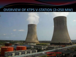
Overview of ktps v station (2×250 mw)
- 2. Introduction to thermal power station About KTPS Principle of operation Coal to steam process Steam to mechanical power Mechanical power to electrical power Electrical power transmission
- 3. About “KTPS” Kothagudem Thermal Power Station First major thermal power station set up in Andhra Pradesh State Electricity Board Basically coal fired thermal power generating station Total installed capacity : 1720W KTPS A Station : Unit 1,2,3&4 of 60MW capacity KTPS B Station : Unit 5&6 of 120 MW capacity KTPS C Station : Unit 7&8 of 120 MW capacity KTPS stage V consists of Unit 9&10 of 250 MW KTPS stage VI produces 500MW
- 4. Coal fired power station Layout of coal fired power station
- 5. Schematic layout of thermal power station
- 6. Principle of operation The three “R” cycles Rankine Cycle Reheat Cycle Regenerative Cycle
- 7. RANKINE CYCLE Schematic layout and Ts diagram for Rankine cycle
- 8. REHEAT CYCLE Ts diagram for Reheat Rankine Cycle
- 9. REGENERATIVE CYCLE Ts diagram for Regenerative Rankine Cycle
- 10. Coal to steam process Coal from the coal wagons in unloaded in the coal handling plant. The coal is transported up to the raw coal bunkers with the help of belt conveyors. Coal is then transported to mills through feeders where the coals are pulverized to powder form. This crushed coal is taken away to the furnace through coal pipes with the help of hot and cold air mixtures from PA fan. PA fan takes atmospheric air, a part of which is sent to air-pre heater for heating while a part goes directly to the mill for temperature control
- 11. Atmospheric air from FD fan is heated in the air heaters and sent to the furnace as combustion air. Water from the boiler feed pump passes through the economizer and reached the boiler drum. Then passes through the down comers goes to bottom ring header. Water from the bottom ring header is divided to all four sides of a furnace. Due to heat and density difference the water raises up in the furnace. This steam and water mixed is taken up to the boiler drum where the steam is separated from water. Water follows the same path while the steam is sent to the super heaters for super heating. The super heaters are located inside the furnace and the steam is superheated and sent to the turbine.
- 12. Flue gases from the furnace is extracted by induced draft fan, which maintains balance in the furnace with the forced draft fan. These flue gases emit their heat energy to various super heaters in three pent houses and finally passes through air pre heaters and goes to electro precipitator where the ash particles are extracted. Electrostatic precipitators consists of metal plates which are electrically charged. Ash particles are attracted on to these plates so that they do not pass though the chimney to pollute the atmosphere. Regular mechanical hammer blows cause the accumulation of ash to fall to the bottom of the precipitator, where they are collected in a hopper for the disposal. The ash is mixed with water to form slurry and is pumped to ash pond
- 13. Steam to mechanical power A steam pipe conveys the steam to the turbine through the stop valve and control valve that automatically regulates the supply of steam to the turbine. Steam from the control valve enters the high pressure cylinder of the turbine, where it passes through a ring of stationary blades fixed to the cylinder wall. These acts as nozzles and direct the steam into a second ring of moving blades mounted on a disc secured to a turbine shaft. This second ring turns the shaft as a result of the force of the steam. The stationary and the moving blades together constitute a stages of turbine. The steam passes through each stage in turn until it reaches the end of HP cylinder where heat energy is changed into mechanical energy.
- 14. The steam leaving the HP cylinder goes back to the boiler for reheating and enters into the intermediate pressure cylinder through HRH lines. Hence it passes through another series of stationary and moving blades . Finally steam is taken to the low pressure cylinders, each of which is enters at the center for flowing outwards in the opposite direction through the rows of turbine bladed arrangement is known as double flow to the extremities of the cylinder. As the steam gives its heat energy to drive the turbine, its temperature and pressure falls and it expands. So because of this expansion the blades are much larger and longer towards the low pressure ends of the turbine.
- 15. Mechanical power to electrical power Basic principle of electrical power generation is from Faraday’s laws. It states that “ when a conductor rotates in magnetic field, the emf will be induced in a conductor and is proportional to the rate of change of flux lines cut by the conductor and capacity of the magnetic field.” Magnetic field is obtained from a separate system called the Excitation system. Excitation system is classified into two types ; Static Excitation Brush-less Excitation The speed of the turbine is determined by the electrical system used in the country i.e. 50 Hz. Speed of the turbine : 3000 rpm
- 16. Electrical power transmission Electrical power is usually produced in the stator windings of large modern generators at about 15.75 kV and is fed through terminal connections to one side of a generator transformer that set up the voltage to 220kV and transmitted. Now –a-days power transmission is carried out even with a high voltage of 400kV. Increase of transmission voltage reduces the line losses and increases the efficiency of the overall system.
- 17. Major components of power station MILLS BOILER FANS DEAERATOR ESP (ELECTROSTATIC PRECIPITATORS) STEAM TURBINES CONDENSER PUMPS
- 18. MILLS
- 19. Coal mill principle Coal of less than 50mm size is fed by feeder through central feed pipe into the revolving bowl of the bowl mill. Centrifugal force feeds the coal uniformly between the bull ring and independently rotating spring loaded rolls to travel through the outer periphery of the bowl. The springs, which load the rolls, impart the pressure necessary for grinding. The partially pulverized coal continues to move up over the edge of the bowl due to centrifugal force Coal mill feature 1. Reject Removal :Any tramp iron or dense foreign material in the raw coal feeder, which is difficult to grind, if carried over to the top of the bowl is dropped out through the air stream to the lower part of the mill side housing. The mill rejects can be intermittently taken out from the pyrite hopper, first by closing the inner gate and opening the outer gate of the hopper. 2. Temperature Control: The Bowl mill can be isolated completely for maintenance work by closing the Hot air shut off gates, cold air shut off gates, pulverized discharge valves and seal air valve. 3. Mill air flow :Mill should be operated at the design airflow at all loads. Operating at higher airflow will cause excess wear and fineness will be decreased. If mill is operated at lower airflow, it may result into coal rejects & excess fineness.
- 20. BOILERS
- 21. BOILER Definition of Boiler Steam boiler or simply a boiler is basically a closed vessel into which water is heated until the water is converted into steam at required pressure. This is most basic definition of boiler. Working Principle of Boiler The basic working principle of boiler is very simple and easy to understand. The boiler is essentially a closed vessel inside which water is stored. Fuel (generally coal) is bunt in a furnace and hot gasses are produced. These hot gasses come in contact with water vessel where the heat of these hot gases transfer to the water and consequently steam is produced in the boiler. Then this steam is piped to the turbine of thermal power plant. There are many different types of boiler utilized for different purposes like running a production unit, sanitizing some area, sterilizing equipment, to warm up the surroundings etc.
- 22. Types of Boiler There are mainly two types of boiler – Water tube boiler and fire tube boiler In water tube boiler the water is heated inside tubes and hot gasses surround these tubes. The fire tube boiler consists of numbers of tubes through which hot gasses are passed. These hot gas tubes are immersed into water, in a closed vessel. Actually in fire tube boiler one closed vessel or shell contains water, through which hot tubes are passed. These fire tubes or hot gas tubes heated up the water and convert the water into steam and the steam remains in same vessel. As the water and steam both are in same vessel a fire tube boiler cannot produce steam at very high pressure. Generally it can produce maximum 17.5 kg/cm2 and with a capacity of 9 Metric Ton of steam per hour.
- 23. Schematic diagram of boiler
- 24. FANS FANS FOR POWER PLANT Supply air for combustion in the furnace and for evacuation of the flue gases formed from the combustion. Maintain Balanced Draft inside the furnace. Supply air for cooling of equipments working in hot zones. Supply air for sealing of gates, feeders & mills bearings etc. Air used for combustion is divided into 2 parts: 1.PRIMARY AIR Portion of total air sent through mills to the furnace. This air dries the pulverized coal and transport it to the furnace for combustion. 2.SECONDARY AIR Large portion of total air sent to furnace to supply necessary oxygen for the combustion.
- 25. Classification of fans Classification based on flow of medium: Axial flow fan Radial flow (or) Centrifugal flow Classification based on construction: Induced draft fan (ID fan) Forced draft fan (FD fan) Primary air fan (PA fan)
- 26. DEAERATOR A Deaerator is a device that is widely used for the removal of oxygen and other dissolved gases from the feed water to steamgenerating boilers. In particular, dissolved oxygen in boiler feed waters will cause serious corrosion damage in steam systems by attaching to the walls of metal piping and other metallic equipment and forming oxides(rust). Dissolved carbon dioxide combines with water to form carbonic acid that causes further corrosion. There are two basic types of Deaerator The tray-type (also called the cascade-type) includes a vertical domed deaeration section mounted on top of a horizontal cylindrical vessel which serves as the deaerated boiler feedwater storage tank. The spray-type consists only of a horizontal (or vertical) cylindrical vessel which serves as both the deaeration section and the boiler feedwater storage tank.
- 28. ESP (ELECTROSTATIC PRECIPITATORS) An electrostatic precipitator (ESP), or electrostatic air cleaner is a particulate collection device that removes particles from a flowing gas (such as air) using the force of an induced electrostatic charge. Electrostatic precipitators are highly efficient filtration devices that minimally impede the flow of gases through the device, and can easily remove fine particulate matter such as dust and smoke from the air stream. Basic Principles Electrostatic precipitation removes particles from the exhaust gas stream of an industrial process. Often the process involves combustion, but it can be any industrial process that would otherwise emit particles to the atmosphere. Six activities typically take place: Ionization - Charging of particles Migration - Transporting the charged particles to the collecting surfaces Collection - Precipitation of the charged particles onto the collecting surfaces Charge Dissipation - Neutralizing the charged particles on the collecting surfaces Particle Dislodging - Removing the particles from the collecting surface to the hopper Particle Removal - Conveying the particles from the hopper to a disposal point
- 29. STEAM TURBINES
- 30. Stream turbine A steam turbine is a device that extracts thermal energy from pressurized steam and uses it to do mechanical work on a rotating output shaft. Its modern manifestation was invented by Sir Charles Parsons in 1884 Because the turbine generates rotary motion, it is particularly suited to be used to drive an electrical generator – The steam turbine is a form of heat engine that derives much of its improvement in thermodynamic efficiency from the use of multiple stages in the expansion of the steam, which results in a closer approach to the ideal reversible expansion process. Principle of operation An ideal steam turbine is considered to be an isentropic process, or constant entropy process, in which the entropy of the steam entering the turbine is equal to the entropy of the steam leaving the turbine. No steam turbine is truly isentropic, however, with typical isentropic efficiencies ranging from 20–90% based on the application of the turbine. The interior of a turbine comprises several sets of blades, or buckets as they are more commonly referred to. One set of stationary blades is connected to the casing and one set of rotating blades is connected to the shaft. The sets intermesh with certain minimum clearances, with the size and configuration of sets varying to efficiently exploit the expansion of steam at each stage.
- 31. Difference between impulse and reaction turbine
- 32. Thermal plant efficiency Thermal plant efficiency (or) overall plant efficiency is the ratio of the energy output to the energy input to the thermal power plant (Energy output is measured at the terminal and energy input is the calorific value of the fuel). This efficiency of the thermal power plant can be expressed as the product of the efficiencies of its subsystem: Thermal plant= boiler × cycle × internal turbine × mechanical turbine × generator
- 33. CONDENSER Schematic layout of a typical surface condenser
- 34. CONDENSER Steam-electric power plants utilize a surface condenser cooled by water circulating through tubes. The steam which was used to turn the turbine is exhausted into the condenser. The steam is therefore condensed as it comes in contact with the cool tubes full of circulating water. This condensed steam is withdrawn from the bottom of the surface condenser. The condensed steam is now water, commonly referred to as condensate water For best efficiency, the temperature in the condenser must be kept as low as practical in order to achieve the lowest possible pressure in the condensing steam. Since the condenser temperature can almost always be kept significantly below 100 oC where the vapor pressure of water is much less than atmospheric pressure, the condenser generally works under vacuum. Thus leaks of non-condensable air into the closed loop must be prevented
- 35. PUMPS CONDENSATE EXTRACTION PUMPS VACUUM PUMPS BOILER FEED PUMPS CENTRIFUGAL PUMP
- 36. CONDENSATE PUMP A condensate pump is a specific type of pump used to pump the condensate (water) produced in an HVAC (heating or cooling), refrigeration, condensing boiler furnace or steam system. They may be used to pump the condensate produced from latent water vapor in any of the following gas mixtures: Conditioned (cooled or heated) building air Refrigerated air in cooling and freezing systems Steam in heat exchangers and radiators The exhaust stream of very-high-efficiency furnaces VACUUM PUMPS A vacuum pump is a device that removes gas molecules from a sealed volume in order to leave behind a partial vacuum. The first vacuum pump was invented in 1650 by Otto von Guericke, and was preceded by the suction pump, which dates to antiquity. Pumps can be broadly categorized according to three techniques Positive displacement pumps Momentum transfer pumps Entrapment pumps
- 37. BOILER FEED PUMPS A boiler feedwater pump is a specific type of pump used to pump feedwater into a steam boiler. The water may be freshly supplied or returning condensate produced as a result of the condensation of the steam produced by the boiler. These pumps are normally high pressure units that take suction from a condensate return system and can be of the centrifugal pump type or positive displacement type. CENTRIFUGAL PUMPS Centrifugal pumps are a sub-class of dynamic ax symmetric workabsorbing turbo machinery. Centrifugal pumps are used to transport fluids by the conversion of rotational kinetic energy to the hydrodynamic energy of the fluid flow. The rotational energy typically comes from an engine or electric motor. The fluid enters the pump impeller along or near to the rotating axis and is accelerated by the impeller, flowing radially outward into a diffuser or volute chamber (casing), from where it exits. Common uses include water, sewage, petroleum and petrochemical pumping. The reverse function of the centrifugal pump is a water turbine converting potential energy of water pressure into mechanical rotational energy.
- 38. Typical specifications of boiler feed pump: 1. Motor driven BFP: Number Make Voltage BHP Speed Full load current Starting current Full load efficiency Power factor Type of bearing : : : : : : : : : : one for each pump M/s Hitachi 3300 V AC 1340 kW 3000 rpm 275 Amps 1255 Amps 95% 85% forced oil lubrication
- 39. 2. Turbine driven BFP: Make : Type : M/s Hitachi Limited horizontal, single cylinder, single stage back pressure Maximum speed : Minimum speed of unit including the gear box Steam supply Pressure Temperature Exhaust pressure Wheel diameter No. of stages Critical speed 6041/2880 rpm : 3021/1440 rpm : : : : : : 87.9kg/cm*cm 510 C 3-4kg/cm*cm 650mm 1(one) 7600rpm
- 42. Ash handling plant System Description The ash handling system handles the ash by bottom ash handling system, coarse ash handling system, fly ash handling system, ash disposal system up to the ash disposal area and water recovery system from ash pond and Bottom ash overflow. Description is as follows: A. Bottom Ash Handling System Bottom ash resulting from the combustion of coal in the boiler shall fall into the over ground, refractory lined, water impounded, maintained level, double V-Section type/ W type steel- fabricated bottom ash hopper having a hold up volume to store bottom ash and economizer ash of maximum allowable condition with the rate specified. The slurry formed shall be transported to slurry sump through pipes. B. Coarse Ash (Economizer Ash) handling System Ash generated in Economizer hoppers shall be evacuated continuously through flushing boxes. Continuous generated Economizer slurry shall be fed by gravity into respective bottom ash hopper pipes with necessary slope.
- 43. C. Air Pre Heater ash handling system Ash generated from APH hoppers shall be evacuated once in a shift by vacuum conveying system connected with the ESP hopper vacuum conveying system. D. Fly Ash Handling System Fly ash is considered to be collected in ESP Hoppers. Fly ash from ESP hoppers extracted by Vacuum Pumps up to Intermediate Surge Hopper cum Bag Filter for further Dry Conveying to fly ash silo. Under each surge hopper ash vessels shall be connected with Oil free screw compressor for conveying the fly ash from Intermediate Surge Hopper to silo. Total fly ash generated from each unit will be conveyed through streams operating simultaneously and in parallel. E. Ash Slurry Disposal System Bottom Ash slurry, Fly ash slurry and the Coarse Ash slurry shall be pumped from the common ash slurry sump up to the dyke area which is located at a distance from Slurry pump house.
- 44. Conclusion All the components and parameters of various equipment involved in the power generation are observed. In the case study parameters like condenser duty, vacuum efficiency, cooling water flow, latent heat, performance of condenser and effect of vacuum analyzed and comparison are made.