
Recomendados
Recomendados
Más contenido relacionado
La actualidad más candente
La actualidad más candente (20)
Similar a Notes
Similar a Notes (20)
Último
Último (20)
Notes
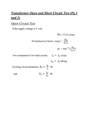
- 1. Transformer Open and Short Circuit Test (Pg 1 and 2) Open Circuit Test
- 2. Theory(Open Circuit) The transformer primary is connected to A.C. supply through ammeter, wattmeter and variac. The secondary of transformer is kept open. Usually low voltage side used as primary and high voltage side as secondary to conduct open circuit test. The primary is excited by rated voltage, which is adjusted precisely with the help of a variac. The wattmeter measures input power. The ammeter measures input current. The voltmeter gives the value of rated primary voltage applied at rated frequency. A voltmeter is connected across secondary to measure secondary voltage when primary is supplied with rated voltage. As voltmeter resistance is very high, though voltmeter is connected, secondary is treated to be open circuit as voltmeter current is always negligibly small. When the primary voltage is adjusted to its rated value with the help of variac, readings of ammeter and wattmeter are to be recorded. The core-loss or iron-loss i.e. the no-load loss in a transformer is determined by performing the open circuit test at normal sine wave impressed voltage. To determine the shunt branch parameter of the equivalent circuit, the LV (low voltage) side is connected to a normal supply voltage and HV (high voltage) side left open. The wattmeter connected in the LV side will then read the total hysteresis and eddy current loss (W0) in the single phase transformer. Since the no-load current is small, the copper losses due to it can be neglected.
- 3. Short Circuit Test Theory(Short Circuit) In this test, HV side is connected to A.C. supply through variac, ammeter and voltmeter. The LV is short circuited with the help of thick copper wire or an ammeter. As ammeter resistance is very low, though ammeter is connected to LV side treated to be short circuited. This test is done on a single phase transformer to find the series parameters of the equivalent circuit. For this test, short circuits of terminals are done in the low voltage side of the transformer and voltage is adjusted so that full- load current flows. The loss during the short circuit will be full load copper losses in both the primary and secondary windings, the core loss being very small, it can be neglected.
- 4. Transformer (HV and LV sides) Theory Here the transformer is energized at rated voltage and the no- load voltage measured. The secondary of the transformer is connected to the load. Now, the load is to be varied from no- load to full-load in steps and various readings of the current and voltages are taken. All the time, keep primary voltage constant at its rated value with the help of variac. The load is increased up to the full-load current and the efficiency and the voltage regulation are found.
- 5. Measurement of power in a three phase unbalanced circuit by two wattmeter method. Determination of steady state response of R-L, R-C and R-L-C circuit and calculation of impedance and power factor. Calibration of ammeter and wattmeter