
Recomendados
Más contenido relacionado
Similar a Learn About LAN Technologies Like Ethernet, Token Ring & Fast Ethernet
Similar a Learn About LAN Technologies Like Ethernet, Token Ring & Fast Ethernet (20)
Más de ssuser50c54b
Último
Último (20)
Learn About LAN Technologies Like Ethernet, Token Ring & Fast Ethernet
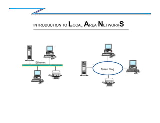
- 1. Token Ring Ethernet INTRODUCTION TO LOCAL AREA NETWORKS
- 2. SEQUENCE LAN Basics Network Operating System Technology Choices Ethernet and Fast Ethernet Basics Implementation Scenarios Token Ring Overview Appendix Charts
- 3. Typical Client Environment Deployment of Personal Computers No standard applications Peripherals supporting a single user PBX ports supporting modems June Monthly Report Prodigy MODEM Word Perfect MODEM CompuServe Microsoft Word A/S400 Terminal Dow Jones MODEM Ami Pro 5250 PC Support No E-MAIL system Mission Critiacl Applications not available to all departments/users No structured wiring system Data sharing by way of diskette
- 4. Client Requirement A/S400 Novell Netware INTERNET Lotus Notes Printer Services Provide users with access to corporate-wide applications and services
- 5. LANs provide the Physical Connection A/S400 INTERNET Ethernet Network Router Lotus Notes Novell Netware With a single network connection the user now has access to these resources
- 6. Network Operating System The Network Operating System (NOS) allows for the sharing of resources, the operating system resides on a server. Workstations that require shared resources are called requesters. LAN Operating Systems Novell Netware IBM Eagle Servers Banyan Vines Windows NT .. Types of Servers Application Communication File Print Remote LAN Access LAN Operating Systems provide: Security – User-ID – Password – Access Control Resource Sharing Types of Requesters DOS OS/2 Netware ... .. NOS Token Ring Requester NOS Ethernet Requester Server
- 7. Technology Choices and Considerations Standards Information – ISO – IEEE Media – The cable type Transmission technique – The method used to carry electrical signals Topology – The physical (or logical) layout Access control – The rules for sharing
- 8. OSI Reference Model OSI - Open Systems Interconnection - a seven layer reference model developed by the International Organization for Standardization. The model provides a standard reference for intercommunication between computer systems through a network using common protocols. The application layer provides services to the actual applications to accomplish information transfer. Applicatio n OSI 7 Presentation The presentation layer is concerned with the representation of user or system data. 6 Session The session layer provides mechanisms for organizing and structuring interaction between applications. 5 Transport The transport layer provides transparent and reliable end to end data transfer, relying on lower layer functions for handling peculiarities of the actual transfer medium. 4 Network The network layer provides the means to establish connections between networks. The standard also includes procedures for the operational control of inter-network communications and for routing of information through multiple networks. 3 Data Link The data link layer provides the functions and protocols to transfer data between network devices and to detect errors that may occur in the physical layer. 2 Physical The physical layer is responsible for physically transmitting the data over the communications link It provides the mechanical, electrical, functional and procedural standards to access the physical medium. 1
- 9. IEEE 802 LAN Standards IEEE 802 - Institute of Electrical and Electronics Engineers Project 802, a set of standards for LAN architectures, giving vendors guidance for designing LAN products. These standards align with the bottom two layers of the OSI Reference Model. The Data Link layer has also been divided into two sublayers. Data Link Physical 2 1 OSI Layers IEEE 802 Layers Logical Link Control IEEE 802.2 Media Access Control IEEE802.3 / 802.5 LLC - The logical link control sublayer is common to all MAC sublayers, in turn it also provides a consistent view of the LAN to the upper layers regardless of the media and protocols being used. MAC - The media access control sublayer describes the access method and contains the mechanisms to control transmissions on the LAN so that two or more stations don't try to transmit data at the same time. The physical connection specifications are also covered in the 802 standard.
- 10. IEEE 802 LAN Standards IEEE 802.1 Higher Layer Interface Standard IEEE 802.2 Logical Link Control Standard Higher Layers Data Link Layer Media Access Sub-Layer Physical Layer CSMA/CD Token Bus Token-Ring Metro Area Network Wireless 100VG Ethernet AnyLAN 802.3 802.4 802.5 802.6 802.11 802.12 LIAISON: ANSI X3T9.5 FDDI ATM ATM Forum EIA-TIA 568 Building Wiring ISO SC25-WG3 Cabling Standards DQDB ADVISORY COMMITTEES: IEEE 802.3u Fast Ethernet IEEE 802.7 Broad Band IEEE 802.8 Fiber IEEE 802.9 Voice/Data Integration IEEE 802.10 LAN Security IEEE 802.14 CATV Wide Area LAN
- 11. Network Communications Protocols Application Presentation Session Transport Network Data Link Physical OSI TCP/IP Applications NetWare Applications Applications APPN 3270 Applications Logical Link Control Media Access Control IEEE802.3 / 802.5 Cabling System TCP IP NLM SPX IPX NetBIOS APPC LU6.2 PU 2.1 Host Terminal Emulation LAN Server Applications
- 12. Media Twisted Pair Shielded Twisted Pair Coaxial Cable Twinaxial Cable CATV Cable Fiber Optics Mixed Media
- 13. Transmission Technique Point-to-point Broadcast Baseband Broadband C F AB CF DG B E G D A C F B E G D C A F Baseband transmission - the entire bandwidth of a channel is devoted to one signal. Bandwidth - the capacity of a communication channel, in digital channels, bandwidth is the rate at which data can be transmitted. Broadband transmission - the bandwidth is shared among transmitting devices.
- 14. Common LAN Topologies mesh Ring bus star tree bus - workstations attached to transmission medium, called a bus. Each frame is broadcast to all stations attached. mesh - every workstation connected to every other workstation ring - each station is connected to its adjacent station by point to point links, thus forming a ring star - each station is connected to a central controlling point, with a point to point connection tree - this topology is a variation of the bus
- 15. Wireless LAN 600 - 800 feet 195 - 250 meters Number of Users Authorized: Unlimited Logged-on: 50 max Number of Cells Per Network: 60 Overlapping: 20+ Open Space Range: Performance Transmission Rate: 1 Mbps Average Real Data Throughput (with compression): .5 - 1.2 Mbps Base Station Remote Station Remote Station Remote Station In-building range and coverage dependent on building construction IBM Wireless LAN Open-space Range: (radius) 800 feet Open-space Coverage: 2.01 million sq ft Base Station 707 sq ft 30 feet IBM Infrared Wireless LAN Range (diameter): Single-room Coverage: 600 feet IBM Wireless LAN Entry Open-space Range: (radius) Open-space Coverage: 1.13 million sq ft Access Point Range & Coverage Characteristics of Radio Frequency Cells
- 16. Physical Implementation of LAN Technologies Today's LANs are designed using a star topology, Ethernet 10BaseT, Fast Ethernet, Token Ring, FDDI and ATM all connect to a central concentrator device. Wiring Closet Concentrator's can be a hub, a switch or a combination of both. Connections to other closets or to a master concentrator form the backbone. Wiring closets are also known as IDF's (intermediate distribution facility) and if used the master concentrator is known as the MDF (main distribution facility) to other wiring closets Concentrator to master concentrator
- 17. Ethernet - CSMA/CD Understanding Carrier Sense Multiple Access with Collision Detection Slot time - the length of time a transmitting station should monitor the bus before transmitting. It is the time during which a collision may occur and is the maximum delay for a transmission to reach the far end of the network and for a collision to propagate back. Slot time is defined to be 51.2 microseconds (512 bit times in a 10Mbps LAN). It also imposes a minimum 64 bytes on the size of the frames transmitted by each station. bus station A station B station C station D idle bus station A wants to transmit station A first listens to see if the bus is idle (slot time) station A determines the bus is idle and transmits data station B has data to transmit station B first listens to see if bus is idle station B determines bus is busy and waits until – medium becomes idle and – the inter packet gap (IPG) expires (9.6 us 10BaseT, .96 us 100BaseT) station A completes its transmission station A and B both want to transmit both station A and B listen station A and B begin to transmit a collision is detected and both stations begin to transmit a jamming signal to alert active stations of the collision in response to this signal each station stops transmitting and uses a back off algorithm to wait
- 18. Ethernet 10BASEn & 100BASEn Standards xBASEn standards define the electrical and mechanical characteristics of the MAU and medium. 10BASEn is defined as: 10 = 10Mbps Base = baseband transmission n = indicates the cable segment length / type Current Ethernet standards: 10BASE5 Thick coaxial cable Commonly known as ThickNet Maximum segment length = 500 meters Maximum number of connections = 100 10BASE2 Thin coaxial cable Commonly known as ThinNet Maximum segment length = 185 meters Maximum number of connections = 30 10BASET Unshielded twisted pair Common known as UTP Maximum segment length = 100 meters 10BASEF Multimode fiber cable Maximum segment length = 2K 100BASEn is defined as: 100 = 100Mbps Base = baseband transmission n = indicates the cable segment length / type Current Ethernet standards: 100BASET Unshielded Twisted Pair (CAT-5) Same characteristics as 10BASET Maximum segment length = 100 meters 100BASET4 Unshielded twisted pair (CAT-3,4,5) Different than 10BASET Uses 3 pair to transmit data Maximum segment length = 100 meters 100BASEF Multimode fiber cable Maximum segment length = 2K
- 19. 10Base5 Overview Terminator 10Base5 MAU AUI Cable 500 meters 10BASE5 Thick coaxial cable Commonly known as ThickNet Maximum segment length = 500 meters Maximum number of connections = 100 Cable type Ethernet 50 ohm PVC of Teflon FEP coaxial Connectors N-Series Termination Segment ends not attached to repeaters must be terminated with 50 ohm terminators Transceiver cable Four stranded, twisted pair conductors with an overall shield and insulating jacket Data Rate 10 Megabits/sec Max. Segment length 500 meters Distances between transceivers 2.5 meter multiples Max. number of transceivers 100 transceivers Max. number of stations per network 1024 adapters Max. transceiver cable length 50 meters Impedance 50 ohms Attenuation 8.5 dB for 500 meters at 10 MHz Max. propagation delay/segment 2165 nanoseconds DC resistance 5 ohms per segment
- 20. 10Base2 Overview 185 meters BNC Connector Terminator 10BASE2 10BASE2 Thin coaxial cable Commonly known as ThinNet Maximum segment length = 185 meter Maximum number of connections = 30 Cable type RG-58A/U, 50 ohm coaxial Connectors BNC type Termination Segment ends not attached to repeaters must be terminated with 50 ohm terminators Transceiver cable Four stranded, twisted pair conductors with an overall shield and insulating jacket Data Rate 10 Megabits/sec Max. Segment length 185 meters Min. distances between T-connectors 0.5 meter Max. number of transceivers 30 transceivers Max. number of stations per network 1024 adapters Max. transceiver cable length 50 meters Impedance 50 ohms Attenuation 8.5 dB for 185 meters at 10 MHz Max. propagation delay/segment 950 nanoseconds DC resistance 10 ohms per segment
- 21. 10BaseT Brings Star Wiring to Ethernet Physical management simplified through star wiring Twisted-pair wiring used in place of coax Intelligent management capability can be added to hub Collision-based access protocol is unchanged Server Management capabilities include, error logging on a station by station basis, (crc checks, collisions) Access control by MAC address, automatic bypass of failed lobes or nics. HUB
- 22. 10BaseT Overview RJ-45 connector both ends HUB 10BASE -T 10BASE-T Unshielded twisted pair Commonly known as UTP Maximum segment length = 100 meters Full Duplex supported Cable type 2 unshielded twisted pairs (UTP) Connectors RJ-45 Termination No external terminators are required Data rate 10 Megabits/sec Single segment length 100 meters (point to point) Max. number of repeaters / segment 2 multiport repeaters Impedance 85-111 ohms Attenuation 8.5 - 10 dB for 100m at 10 MHz Max. propagation delay/segment 1000 nanoseconds
- 23. 100BaseT Overview RJ-45 connector both ends HUB 100BASE -T 100BASE-T Unshielded twisted pair Must use Category 5 UTP Maximum segment length = 100 meters Full Duplex supported Cable type 2 unshielded twisted pairs (UTP) Connectors RJ-45 Termination No external terminators are required Data rate 100 Megabits/sec Single segment length 100 meters (point to point) Max. number of repeaters / segment 2 multiport repeaters Impedance 85-111 ohms Attenuation 8.5 - 10 dB for 100m at 10 MHz Max. propagation delay/segment 1000 nanoseconds
- 24. 100BaseT4 Overview RJ-45 connector both ends HUB 100BASE -T4 100BASE-T4 Unshielded twisted pair Support for Cat 3,4,5 Requires 4 Pair *Uses 3 pair for transmitting data and 1 pair for signaling Maximum segment length = 100 meters **Full Duplex not supported Cable type 4 unshielded twisted pairs (UTP) Connectors RJ-45 Termination No external terminators are required Data rate 100 Megabits/sec Single segment length 100 meters (point to point) Max. number of repeaters / segment 2 multiport repeaters Impedance 85-111 ohms Attenuation 8.5 - 10 dB for 100m at 10 MHz Max. propagation delay/segment 1000 nanoseconds
- 25. Repeater OSI Reference Model Application Presentation Session Transport Network Data-Link Physical Physical Physical Application Presentation Session Transport Network Data-Link Physical Repeater
- 26. Repeaters MAU AUI Cable Terminator 500 meters MAU AUI Cable Terminator 500 meters REPEATER Link Segment Link Segment Collision Domain Network Use when: The cable length exceeds recommended length The number of attachments exceeds 100 Planning considerations: Repeaters must be placed at the end of the link segment Each repeater counts as an attachment No more than 4 repeaters in a collision domain No active duplicate paths between any two DTE's Repeaters operate at the Physical Layer Application Presentation Session Transport Network Data-Link Physical OSI Reference Model
- 27. 10Mbps Ethernet Repeater Rule REPEATER REPEATER REPEATER REPEATER 5-4-3-2-1 4-3-2 5- no more than 5 segments 4- no more than 4 repeater hops 3- only 3 segments with nodes 2- inter-repeater links 1- makes 1 large collision domain Collision Domain Network 10Base5 2500m
- 28. 100Mbps Ethernet Repeater Rule For 100Mbps Ethernet the IEEE has designated two repeater classes. The class designation coincides with the latency of the repeater. Total network segment length is significantly reduced as compared to 10Mbps Ethernet. Class 1 Counts as 1 Hop 100m 100m Collision Domain Network 100BaseT 200m Class 1 - only one repeater hop Inter-repeater Link 5m max. 100m 100m Collision Domain Network 100BaseT 205m Counts as 2 Hops Class 2 - up to two repeater hops Class 2 Class 2
- 29. Coexistence of 10BaseT and 100BaseT As a network managers migrate to higher speed technologies, the current install base needs to be considered. The products available today help to protect that investment. The AS/400 doesn't have available the 100Mbps card for Ethernet, the AS/400 can coexist in this environment. When purchasing new PC's install 10/100 cards if the plan is to move to Fast Ethernet to the desktop. Wiring Closet 100Mbps connection 10BaseT HUB 10BaseT connection 100BaseT HUB 100BaseT 10BaseT 10BaseT 100BaseT Switched Uplink
- 30. 100Mbps Backbone Implementation Ethernet Stackable Hub 100BaseT Ethernet Switch 10BaseT Ethernet Stackable Hub 10BaseT Fiber Expansion Module (Switched) 100BaseT Universal Feature Card (UFC) 100BaseF Fiber Connection 100BaseT Copper Connection 10BaseT Copper Connection Multimode Fiber Building 1 Building 2 10BaseT 100BaseT 10BaseT
- 31. 100Mbps Backbone Implementation Building 1 Building 2 Ethernet Collision Domain Ethernet Switch 10BaseT or 100BaseT 100BaseF Ethernet 100BaseT Ethernet 10BaseT Ethernet x X X x X X X Shared Ethernet Segment
- 32. Legacy Backbone Implementations Networks were designed to segment users at the floor level and connect to either a distributed or collapsed backbone. The collapsed backbone design made the management of the floor segment easier since there was the presence of each segment in a central location. Typically the backbone segment ran at the same speed as the floor segments, a second backbone using a alternate path would be installed for redundancy Fourth Floor Third Floor Second Floor First Floor Basement Server HUB HUB HUB HUB HUB B B B B B Fourth Floor Third Floor Second Floor First Floor Basement Server HUB HUB HUB HUB HUB B B B B B
- 33. Switched Network Implementation Fourth Floor Third Floor Second Floor First Floor Basement Server HUB HUB HUB HUB HUB B B B B B Legacy Network Example Fourth Floor Third Floor Second Floor First Floor Basement Server HUB HUB HUB HUB HUB EthernetSwitch Switched Network Example The bridges are replaced with a switch, collapse backbone design, the server is moved to a switch port
- 34. Star-Wired Token Ring Wiring concentrator converts physical star to logical ring Physical management is simplified by star wiring Intelligence in adapter, not concentrator
- 35. Token Ring Overview Multi Station Access Unit W1 W2 W3 W4 RI RO W1 W2 W4 W3 Token Ring Networks Use twisted pair media UTP STP Operate at 4Mbps 16Mbps Connect to wiring concentrators Passive Active Implemented using a star topology Frames are sent sequentially around the ring
- 36. Extending Token Ring Segments Multi Station Access Units are connected via the RI / RO ports using patch cables RI RO Multi Station Access Unit RI RO RI RO RI RO W1 W2 W4 W3 W9 W10 W12 W11 W20 W19 W17 W18 W28 W27 W25 W26 W1 W9 W17
- 37. Workstation Insertion onto Ring W1 W2 W3 W4 Lobe Test Cable wrap test to MSAU If successful the MSAU relay is opened The workstation is attached Monitor Check Waits for Active_Monitor_Present, Standby_ Monitor_Present, or Ring_Purge MAC frame If seen the workstation will assume standby monitor Duplicate Address Check Sends a duplicate address test MAC frame, if duplicate address is found, the workstation will detach Participation in Neighbor Notification Learns its nearest active upstream neighbor (NAUN) and reports its own address to its active downstream neighbor Request Initialization A Request_Initialization MAC frame is sent to the ring parameter server, the ring parameter server responds with an Initialize_Ring_Station MAC frame. Parameters which can be set are physical location, ring number and ring authorization level.
- 38. Appendix Charts
- 39. Connecting Networks Using Bridges Purpose: connect two separate networks(i.e. collision domain networks) can be local or remote selectively forwards information between the networks Use when network: traffic needs to be segmented protocols are different are geographically dispersed Types: Transparent Source Route Source Route Transparent Translational Bridges operate at the Data-Link layer Network A Network B Bridge Physical Address 001 Physical Address 002 Physical Address 101 Physical Address 102 OSI Reference Model Application Presentation Session Transport Network Data-Link Physical Data-Link Physical Data-Link Physical Application Presentation Session Transport Network Data-Link Physical Bridge Appendix
- 40. Transparent Bridge Transparent – also called learning or spanning tree – based on the principle that a sending device can transmit a frame to a receiving device without having any knowledge of that devices location – frames are forwarded based on the MAC sublayer destination address – a filtering database is maintained in the bridge of all known source address's – each bridge counts as an attachment – no active duplicate paths between any two networks Network A Network B Bridge Physical Address 001 Physical Address 002 Physical Address 101 Physical Address 102 Transparent Address Port 001 A 002 A 101 B 102 B Filtering Database B A Appendix
- 41. Source Route Bridge Source Route – requires sending device to specify the path the frame should take to the receiving device – the best path is determined by the discovery process – the sending device sends a discovery frame to the destination device – the destination device responds with a discovery response frame marked all routes broadcast Physical Address 001 Physical Address 002 Ring 001 Ring 100 Physical Address 101 Physical Address 102 Bridge Source Route – as this frame passes through each bridge the bridge number and the ring it is associated with is inserted in the routing information field – no more than 7 hops in a bridge network – the sending device can receive more than one response frame – the sending device then picks the best route Ring 010 Bridge Source Route Bridge Source Route A B C Appendix
- 42. Remote & Translational Bridges Remote Bridges communicate via the wide area network Network A Bridge Physical Address 001 Physical Address 002 Network B Physical Address 101 Physical Address 102 Bridge DSU DSU WAN Network A Bridge Physical Address 001 Physical Address 002 Bridges can connect different media types i.e.. Ethernet to Token Ring Network B Appendix
- 43. LAN Switching Similar to a multiport transparent bridge Forwards frames based on the destination MAC address Able to forward frames at media speed (on the fly switching) Collision domains stop at the switch port Two types of LAN segments can be attached Shared Media Dedicated Can be connected to a hub or repeater port Can replace backbone network with switch Increases backbone throughput by Switch ports can be configured for full or half duplex Switches can be cascaded to support additional segments Uplinks available to connect to Higher Speed Networks An AUI port is provided to connect to 10BASE2, 10BASE5, or Fiber Ethernet Switching Switches operate at the Data-Link layer OSI Reference Model Application Presentation Session Transport Network Data-Link Physical Data-Link Physical Data-Link Physical Application Presentation Session Transport Network Data-Link Physical Switch 10Mbps x # of ports 2 Appendix
- 44. Switch Implementation Example HUB HUB HUB HUB Typical Ethernet Implementation Switched Ethernet Implementation FDX Server HUB HUB Ethernet Switch HUB HUB Appendix
- 45. Routers Purpose: Receive and transmit multiple protocols from one LAN to another Use when: Network layer protocols require frames to be routed Examples of routable protocols: Internet Protocol - IP Internet Packet Exchange - IPX Internetwork Datagram Protocol - IDP Routers operate at the Network layer Router Network Address 295.10 PNA 101 LNA 295.10.1 PNA 102 LNA 295.10.2 Network Network OSI Reference Model Application Presentation Session Transport Network Data-Link Physical Data-Link Physical Data-Link Physical Application Presentation Session Transport Network Data-Link Physical Route r Network Address 296.20 PNA 201 LNA 296.20.1 PNA 202 LNA 296.20.2 Router Network Address 294.01 PNA 001 LNA 294.01.1 PNA 002 LNA 294.01.2 Router WAN Routers are configured with the network layer address of each of its network connections Routing tables are maintained about each router in the network The configuration of the network can be static or dynamic Appendix
- 46. Gateways Network A Physical Address 001 Physical Address 002 DSU DSU WAN AS/400 Gateways operate at the Upper Layers of the OSI Model Application Presentation Session Transport Network Data-Link Physical OSI Reference Model Application Presentation Session Transport Network Data-Link Physical Application Presentation Session Transport Network Data-Link Physical Application Presentation Session Transport Network Data-Link Physical Gateway PC Gateway Forward packets of data between dissimilar networks Operates at the transport layer and above Gateway types: PC 3270 Control Unit FEP Channel (Local) Remote Appendix