
Recomendados
Más contenido relacionado
La actualidad más candente
La actualidad más candente (20)
Similar a Equal Area Criterion for Transient Stability Studynew.pptx
Similar a Equal Area Criterion for Transient Stability Studynew.pptx (20)
Último
Último (20)
Equal Area Criterion for Transient Stability Studynew.pptx
- 1. Equal Area Criterion for Transient Stability Assessment Prof. V. B. Pandya Asst. Prof. (EE)
- 2. Roadmap Concept of equal area criterion Transient stability assessment using equal area criterion for sudden increase in mechanical input to turbine First swing stability and instability for sudden increase in mechanical input Fault at generator terminals – cleared quickly Sudden short circuit of one of parallel lines
- 3. Concept of Equal Area Criterion • Single machine connected to infinite bus (SMIB) system can be used to assess transient stability by means of simple criterion known as Equal Area Criterion without going for numerical solution of swing equation • For a single machine connected to infinite bus system 2 2 1 ( ) sin a m e a s e L d V P d P P where P Accelerating Power dt M M d dt E P X X jXL + E’/δ Pe jXd’ V/0 Fixed (Infinite Bus) Pm
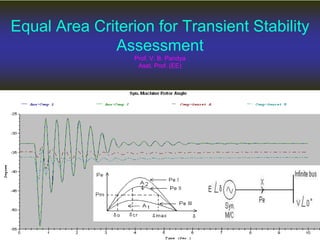
- 4. Concept of Equal Area Criterion • If system is unstable, continues to increase indefinitely with time and machine loses synchronism. • On the other hand, performs oscillations whose amplitude decreases in actual practice because of damping. These two situations are shown in below fig. • It can be visualized that for a stable system, indication of stability will be given by observation of the first swing, where will go to maximum and will start decreasing. This fact can be stated as a stability criterion.
- 5. Concept of Equal Area Criterion • Thus criterion for stability mathematically 0 . 0 . d i e system is stable dt d i e system is unstable dt • This leads to concept of equal area criterion as follows: 0 0 0 2 2 2 2 2 1 ( ) 1 2 2 ( ) 2 ( ) 2 2 ( ) a m e m e m e m e a P d P P dt M M d d d P P dt dt dt M Integrating above d P P d dt M d P P d P d dt M M
- 6. Concept of Equal Area Criterion • Here δ0 is initial rotor angle before it begins to swing due to perturbation 0 0 0 2 2 ( ) 0 0 m e a a For stable system d P P d P d dt M M P d • The condition of stability can be stated as: “The system is stable if the area under Pa (accelerating power)- curve reduces to zero at some value of power angle”. In other words, the positive (accelerating) area under Pa- curve must equal the negative (decelerating) area and hence the name “equal area” criterion of stability.
- 7. Concept of Equal Area Criterion • Ans:- Synchronous machine relative speed – The equation gives relative speed of machine with respect to the synchronous revolving reference frame – If stability of system needs to be maintained, the relative speed equation must be zero sometimes after the disturbance 2 o o m e s f d P P d dt H • What does dδ/dt signify?
- 8. Sudden Change in Mechanical Input 1 2 0 1 1 1 2 1 1 2 ( ) , ( ) m e e m A P P d A P P d A A Pe 0 0 e m P P A δ δ0 Π • Consider an SMIB system with machine operating at A (δ0,Pe0) • Increase Pm0 suddenly to Pm1. 1 m P δ2 B δ1 • Pm1> Pe0 =>Pa increases i.e dω/dt = (Pm-Pe)/M =>ω increases from ωs and since ω> ωs and dδ/dt = ω- ωs => δ0 increases to δ1 and hence Pe = E’ V sin δ /(Xd’+XL)=>Pe increases to point B from A. • At B Pm1 = Pe now so Pa=0 and rotor starts decelerating such that ω stops increasing but still ω> ωs so δ1 further increases till δ2 at C where ω = ωs i.e. dδ/dt = 0. C A2 •As the generator continues to slow, dδ/dt becomes negative due to ω < ωs. Since ω< ωs, δ (δ2) decreases towards B being first swing stable! Here Area A1=A2 i.e. State point will overshoot point B (where Pa=0) also due to rotor inertia towards A & oscillates around B 2 0 0 a P d
- 9. First swing stability- Qualitative Behavior Pm0=Pe0 Pe δ δ0 A B C Time δ First swing Stable at δ2 δ1 δ0 0 0 δ1 Stable Equilibrium δ2 s d dt
- 10. First swing stability- Qualitative Behavior Unstable Equilibrium max 1 •Any further increase in Pm means the area available for A2 (decelerating) is less than A1 (accelerating) so that the excess kinetic energy causes rotor angel δ to increase beyond point C and decelerating power becomes accelerating power resulting into instability of system. Pe 0 0 e m P P A δ0 Π 1 m P δ2 = δmax B δ1 C ω-ωsyn δ Time A2
- 11. Fault at generator terminals – cleared quickly A, AB : Fault occurs Pm>Pe ω ↑ δ↑ (δ0 → δ1) B, CD : Fault Cleared Pm < Pe, ω > ωsyn, dδ/dt ↓ but δ↑(δ1 → δ2) D Pm<Pe ω =0 ↓ δ mom. constant DE : Pm<Pe ω < ωsyn ↓ δ ↓ Swings back! Pm=constant δ P δ0 D Pe during fault, from A to B A B C E Pe ∞ Pm δ1 δ2 Pe - pre and post fault Pmax A1 A2
- 12. Fault at generator terminals – Critical clearing angle(δcr) and critical clearing time(tcr) If clearing is delayed such that δ2 becomes δmax as shown where A1=A2. Any further delay in clearing fault results into A1>A2 making system unstable. Pm=constant Pe - pre and post fault δ P δ0 Pmax D Pe during fault, from A to B A B C E δcr δmax A1 A2
- 13. Derivation of δcr and tcr when Pe=0 during fault 0 max max 0 max 0 1 0 2 max 2 max max max 1 2 max 0 max max max 0 max 0 0 sin 0 sin cos cos cos cos (1) sin (1) cos 2 s cr cr e m m cr m cr m cr m cr m cr P P A P d P A P P d A P P for stability A A P P put and P P in 0 0 in cos
- 14. Derivation of δcr and tcr when Pe=0 during fault 2 2 2 0 2 0 0 , . 1 0 int . 1 2 1 2 2 m e m cr m cr cr cr m During fault swing equ d P as P dt M egrating twice above equ P t M P t M M t P
- 15. Sudden short circuit of one of parallel lines Case -1 : Fault at generator end of line
- 16. 1 1 2 1 1 ' ( ) Pr sin || ( ) 0 ' ( ) sin eI d eII eIII d E V i efault P X X X ii During fault P E V iii Postfault P X X A1 A2
- 17. Case -2 : Fault away from generator end on line (middle)
- 18. max 0 1 1 2 1 max 1 1 max 1 max 2 max ' ' ( )Pr , sin ( ) , sin || ' ( ) , sin ... sin ( sin ) , ( sin ) cr cr eI eII d II m eIII d III m II III m E V E V i efault P ii During fault P X X X X P E V iii Postfault P and X X P A P P d A P P d δmax
- 19. Derivation of δcr max 0 max max 0 max 0 max max max cos cos 0 ( ) (cos cos ) 0 (cos cos ) ( ) cr cr m II III m m cr II cr III cr m cr P P P P OR P P P P max max 0 max max max max ( ) cos cos 180 cos m cr III III cr III II P P P P P
- 20. Case -3 : Reclosure
- 21. If CB of line 2 are successfully reclosed, power transfer once again becomes Case -3 : Reclosure 1 1 2 max ' sin || sin eIV d I E V P X X X P Since reclosure restores power, changes of stable operation improves.
- 22. Case -3 : Reclosure 1 1 max max sin m I P P For critical clearing angle, 0 max max max max ( sin ) ( sin ) ( sin ) , & cr rc cr rc m II III m I m rc cr P P d P P d P P d where t t Time between clearing reclosure
- 23. Example • A generator operating at 50 Hz delivers 1 pu power to an infinite bus through a double circuit transmission line in which resistance is neglected. A fault takes place reducing the maximum power transfer to 0.5 pu whereas before fault, this power was 2.0 pu. and after fault clearance, it is 1.5 pu. By equal area criterion determine the critical clearing angle.
- 24. Example 0 max max max 1 , 2, 0.5, 1.5 m e I II III P P initial loading P P P 1 0 max sin 0.532 m I P rad P 1 max max sin 2.41 m III P P rad
- 25. Example max max 0 max max max max ( ) cos cos 180 cos 1.0(2.41 0.523) 0.5cos0.523 1.5cos2.41 1.5 0.5 0.337 70.3 m cr III III cr III II P P P P P rad