SlideShare una empresa de Scribd logo
1 de 62
Descargar para leer sin conexión
Syllabus for Interview


1) Hardware
2) Networking
3) CCNA
4) Redhat
5) It Security

Hardware

1) Motherboard
a) North Bridge (MCH (memory controller hub))
b) South Bridge (ICH (I/O controller Hub))
       Motherboard has to very important component North Bridge and south bridge.
Both have different –different work. Both are chips on the mother board.
       Another Name of North Bridge is MCH/IMCH (memory controller hub/integrated
memory controller hub). It is used to manage communication between RAM, CPU, AGP,
and chach memory.
       Another Name of south bridge is ICH. Rest of the component which is not
handled by the north bridge. Like PCI SLOT, USB, ISA IDE BIOS LEGACY.


                                                                               1
ZERO LEVEL FORMATTING
  1) For Zero level formatting you have to insert windows 98 cd in cdrom and restart
     system boot via cd rom
  2) You find command prompt and go to cd rom
  3) A:> G: suppose A is default prompt and G is 98 prompt
  4) G:> dir
  5) G:>cd Dm
  6) G:DM>dir
  7) G:DM>cd DmSam
  8) G:DMDMSAM>DIR
  9) G:DMDMSAM>DM /X/M

RAID (redundant array of independent disks; originally redundant array of
inexpensive disks)
RAID is a way of storing the same data in different places (thus, redundantly) on multiple
hard disk . By placing data on multiple disks, I/O (input/output) operations can overlap in
a balanced way, improving performance.

    RAID-0: This technique has striping but no redundancy of data. It offers the best
     performance but no fault-tolerance.
    RAID-1: This type is also known as disk mirroring and consists of at least two
       drives that duplicate the storage of data. There is no striping. Read performance is
       improved since either disk can be read at the same time. Write performance is the
       same as for single disk storage. RAID-1 provides the best performance and the
       best fault-tolerance in a multi-user system.
    RAID-2: This type uses striping across disks with some disks storing error
     checking and correcting (ECC) information. It has no advantage over RAID-3.
    RAID-3:      This type uses striping and dedicates one drive to
     storing parity information. The embedded error checking (ECC) information is
     used to detect errors. Data recovery is accomplished by calculating the exclusive
     OR (XOR) of the information recorded on the other drives. Since an I/O operation
     addresses all drives at the same time, RAID-3 cannot overlap I/O. For this reason,
     RAID-3 is best for single-user systems with long record applications.
    RAID-4: This type uses large stripes, which means you can read records from any
     single drive. This allows you to take advantage of overlapped I/O for read
     operations. Since all write operations have to update the parity drive, no I/O
     overlapping is possible. RAID-4 offers no advantage over RAID-5.
    RAID-5: This type includes a rotating parity array, thus addressing the write
       limitation in RAID-4. Thus, all read and write operations can be overlapped.
       RAID-5 stores parity information but not redundant data (but parity information


                                                                                         2
can be used to reconstruct data). RAID-5 requires at least three and usually five
        disks for the array. It's best for multi-user systems in which performance is not
        critical or which do few write operations.
    RAID-10: Combining RAID-0 and RAID-1 is often referred to as RAID-10,
        which offers higher performance than RAID-1 but at much higher cost. There are
        two subtypes: In RAID-0+1, data is organized as stripes across multiple disks,
        and then the striped disk sets are mirrored. In RAID-1+0, the data is mirrored and
        the mirrors are striped.
Small Computer System Interface (SCSI)
Internal memory
Ram (Random access memory)
Rom (Read only memory)

   1. ROM - Read Only Memory
   2. PROM - Programmable Read Only Memory
   3. EPROM - Erasable Programmable Read Only Memory (UV RAYS)
   4. EEPROM - Electrically Erasable Programmable Read Only Memory (high
      voltage of electric)
   5. Flash EEPROM memory

BIOS=It stands for Basic input output system. It is also known as ROM (Read Only
Memory). It is the boot firmware program on a PC, and controls the computer from the
time you start it up until the operating system takes over. When you turn on a PC, the
BIOS first conduct a basic hardware check, called a Power-On Self Test (POST), to
determine whether all of the attachments are present and working. Then it loads the
operating system into your computer's random access memory, or RAM.
       The BIOS also manages data flow between the computer's operating system and
attached devices such as the hard disk, video card, keyboard, mouse, and printer.
       The BIOS stores the date, the time, and your system configuration information in
a battery-powered, non-volatile memory chip, called a CMOS (Complementary Metal
Oxide        Semiconductor)           after      its       manufacturing        process.
        Although the BIOS is standardized and should rarely require updating, some older
BIOS chips may not accommodate new hardware devices. Before the early 1990s, you
couldn't update the BIOS without removing and replacing its ROM chip. Contemporary
BIOS resides on memory chips such as flash chips or EEPROM (Electrically Erasable
Programmable Read-Only Memory), so that you can update the BIOS yourself if
necessary.

POST= It stands of Power on self test. The POST is a test the computer must complete
to verify all hardware is working properly before starting the remainder of the boot
process. If the computer passes the POST the computer will often return a single beep
and if unsuccessful will create a beep code that indicates the error.


                                                                                        3
Networking

What is network?
         A network consists of two or more computers that are linked in order to share
resources (such as printers and CDs), exchange files, or allow electronic communications.
The computers on a network may be linked through cables, telephone lines, radio waves,
satellites, or infrared light beams. Wired and wireless both are called communication
media.
         Communication media – there are two types of communication media.
1) Wired
2) Wireless
1) Wired- in wired communication media
Angina three types
A) Coaxial cable (connector BNC=births novel connector)
 I) thin net coaxial cable (RG 58)
 ii) Thick net coaxial cable (RG 8)
B) Twisted pair cable (RJ45)
 I) UTP (unshielded twisted pair cable)
 ii) STP (shielded twisted pair cable)

c) Fiber optic cable (SC=subscriber connector, ST=straight tip connector)
 i) Single mode fiber optic cable
 ii) Multimode fiber optic cable

Some important terms of networking -:

1) MAC Address
2) IP Address
3) NIC
4) HUB
5) SWITCH
6) ROUTER
7) BRIDGE
8) MODEM
9) ACCESS POINT
10) COLLISION DOMAIN
11) BROADCAST DOMAIN
12) VPN (VITUAL PRIVATE NETWORK)
13) NODE
14) HOST
15) FIREWALL
16) TRANSCIVER
1) MAC Address:- (Media access control) It is also known as hardware address or
physical address of a devices. It is 12 digit hexadecimal number and 48 bit binary
number. It is representing in hexadecimal number. Broadcast Mac address FF: FF: FF:


                                                                                       4
FF: FF: FF(layer two Broadcast address). First 6 digits are manufacture id and another six
digit are client id which is maintained by manufacturer. MM:MM:MM:SS:SS:SS

2) IP ADDRESS:- (Internet protocol ) It is logical address of a device . It is 32 bit binary
number which is represent in decimal format and it is divided into 4 octets and each octet
is separated by each other by dot (.). In a single network any ip address should not be
same otherwise ip conflicted error will come. Broadcast Ip address 255.255.255.255
(layer three Broadcast address).

3) NIC:-It stands for network interface card . In computer networking, a NIC provides
the hardware interface between a computer and a network. A NIC technically is network
adapter hardware in the form factor of an add-in card such as a PCI or PCMCIA card.
This is the card that physically makes the connection between the computer and the
network cable.

4) HUB:- Hub is a network connectivity device and it is work on layer one of osi model
devices. It is work in half duplex mode. Hub received data packet from a computer and
Broadcast it to all devices. In a hub one collision domain and one broadcast domain.
   Collision domains are found in a hub environment where each host segment connects
to a hub that represents only one collision domain and only one broadcast domain.
Collision domains are also found in wireless network such as wi-fi.

5) SWITCH:-Switch is also network connectivity devices; it is work on layer two of osi
model. It works on full duplex mode. A switch has 1 collision domain per interface. And
one broadcast domain. Switch create Mac table by using hardware chip ASIC
(Application Specific Integrated Circuit)

6) ROUTER:- A router is a internet work connectivity device that is used to
communicate one network to another network. Routers operate at the network layer (OSI
Model's layer 3). The primary function of a router is to connect networks together and
keep certain kinds of broadcast traffic under control. There are several companies that
make routers: Cisco (Linksys), Juniper, Nortel (Bay Networks), Redback, Lucent, 3com,
and HP just to name a few.
 Restrict network broadcasts to the LAN
 Act as the default gateway.
 Move data between networks
 Learn and advertise loop free paths

Router works two types of protocol Routed and Routing protocol. A routed protocol can
be routed by a router, which means that it can be forwarded from one router to another.
A routed protocol contains the data elements required for a packet to be sent outside of its
host network or network segment. In other words, a routed protocol can be routed.
Routed protocols                 are               IP              and                IPX.
Routing protocol select the best path for packet transmission of remote network. example
rip eigrp ospf is routing protocol.


                                                                                          5
7) BRIDGE:-It is used to connect two different network segment in a Lan.
A bridge device filters data traffic at a network boundary. Bridges reduce the amount of
traffic on a LAN by dividing it into two segments. Bridges operate at the data link layer
(Layer 2) of the OSI model. Bridges inspect incoming traffic and decide whether to
forward or discard it. An Ethernet bridge, for example, inspects each incoming Ethernet
frame - including the source and destination MAC addresses, and sometimes the frame
size - in making individual forwarding decisions.

8) MODEM:- It is called modulator-demodulator. It is convert digital signals into analog
signals it is called modulation and transmits it. At the receiving end angina it convert
analog signal into digital signal it is called demodulation.

9) ACCESS POINT :- Wireless access points (APs or WAPs) are specially configured
nodes on wireless local area networks (WLANs). Access points act as a central
transmitter and receiver of WLAN radio signals.Access points used in home or small
business networks are generally small, dedicated hardware devices featuring a built-in
network adapter, antenna, and radio transmitter. Access points support Wi-Fi wireless
communication standards.

10) COLLISION DOMAIN:- A collision domain is an area on the network where two
devices may attempt to transmit at the same time. A hub has 1 collision domain overall.
A switch has 1 collision domain per interface.

11) BROADCAST DOMAIN:- A broadcast domain is a logical division of a computer
network, in which all nodes can reach each other by broadcast at the data link layer. A
broadcast domain can be within the same LAN segment or it can be bridged to other
LAN segments. In a switch one broadcast domain.
         If any switch has 12 ports then one Broadcast domain and 12 collision domain in
it. If any hub has 12 ports then single collision domain and single broadcast domain.

12)VPN:- A Virtual Private Network (VPN) is a network technology that creates a secure
network connection over a public network such as the Internet or a private network
owned by a service provider. Large corporations, educational institutions, and
government agencies use VPN technology to enable remote users to securely connect to a
private network.

13) NODE:- In networks, a processing location. A node can be a computer or some
other device, such as a printer. Every node has a unique network address, sometimes
called a Data Link Control (DLC) address or Media Access Control (MAC) address.
A node can be a computer and terminal and any other devices.

14) HOST:-In a computer network host has a unique ip address. And it has some data. A
computer that is connected to a TCP/IP network, including the Internet. Each host has a
unique IP address.


                                                                                       6
15) FIREWALL:-Firewall is both hardware and software devices. A system designed to
prevent unauthorized access to or from a private network. Firewalls can be implemented
in both hardware and software, or a combination of both. Firewalls are frequently used to
prevent unauthorized Internet users from accessing private networks connected to the
Internet, especially internet. All messages entering or leaving the intranet pass through
the firewall, which examines each message and blocks those that do not meet the
specified security criteria.

16) TRANSCIVER =Network Transceivers, short for transmitter-receiver, are devices
that both transmit and receive analog or digital signals. The term is used most frequently
to describe the component in a local-area network (LAN) that actually applies signals
onto the network wire and also detects signals passing through the same wire. For many
LANs, the transceiver is built directly into the network interface card (NIC). Some types
of       networks,       however,         require       an       external      transceiver.
        Network transceivers are available in three main configurations: chip, board, or
module style. Chip style network transceivers are the smallest type. They can easily be
inserted into or removed from a network system. Board style devices are built directly
into a network board or card. Module transceivers are external to the network, and are
installed and function similarly to other computer peripherals, or they may function as
stand-alone devices.

TYPES OF NETWORK:

Basically there are three types of network:-
1) LAN
2) WAN
3) MAN

1) LAN:-LAN stands for local area network. It is a computer network which is connoted
with each other and shair their resources and information but not connected to the internet
is called LAN.

2) WAN:-WAN stands for wide are network. A WAN spans a large geographic area,
such as a state, province or country. WANs often connect multiple smaller networks,
such as local area networks (LANs) or metro area networks (MANs).
The world's most popular WAN is the Internet. Some segments of the Internet, like VPN-
based extranets, are also WANs in themselves. Finally, many WANs are corporate or
research networks that utilize leased lines.
WANs generally utilize different and much more expensive networking equipment than
do LANs. Key technologies often found in WANs include SONET, Frame Relay,
and ATM.

3)MAN:- Man stand for Metropolitan area network. A network spanning a physical area
larger than a LAN but smaller than a WAN, such as a city. A MAN is typically owned an
operated by a single entity such as a government body or large corporation.


                                                                                         7
NETWORK MODEL:-

There are three types of network model
1) Peer to peer
2) Server client
3) Central computing
1) PEER TO PEER =Peer-to-peer (abbreviated to P2P) refers to a computer network in
which each computer in the network can act as a client or server for the other computers
in the network, allowing shared access to files and peripherals without the need for a
central server. P2P networks can be set up in the home, a business or over the Internet.
Each network type requires all computers in the network to use the same or a compatible
program to connect to each other and access files and other resources found on the other
computer. P2P networks can be used for sharing content such as audio, video, data or
anything in digital format.


2) SERVER CLIENT =The client/server model is a computing model that acts
as distributed application which partitions tasks or workloads between the providers of a
resource or service, called servers, and service requesters, called clients. Often clients and


                                                                                            8
servers communicate over a computer network on separate hardware, but both client and
server may reside in the same system. A server machine is a host that is running one or
more server programs which share their resources with clients. A client does not share
any of its resources, but requests a server's content or service function. Clients therefore
initiate communication sessions with servers which await incoming requests.


3) CENTRAL COMPUTING =Centralized computing is computing done at a central
location, using terminals that are attached to a central computer. The computer itself may
control all the peripherals directly (if they are physically connected to the central
computer), or they may be attached via a terminal server. Alternatively, if the terminals
have the capability, they may be able to connect to the central computer over the
network. The terminals may be text terminals or thin clients, for example. In this type of
model a machine process all the data and other computer in network work like as dump
terminal they can only provide the input and see the output.

NETWORK TOPOLOGYES -

The specific physical, i.e., real, or logical, i.e., virtual, arrangement of the elements of a
network. Note 1: Two networks have the same topology if the connection configuration
is the same, although the networks may differ in physical interconnections, distances
between nodes, transmission rates, and/or signal types. Note 2: The common types of
network topology are illustrated and defined in alphabetical order below. There are two
type of network topology. 1) logical and 2) physical topology .


                                                                                            9
1)LOGICAL TOPOLOGY =Logical topology (also referred to as signal topology) is a
network computing term used to describe the arrangement of devices on a network and
how they communicate with one another.
        Logical topologies are bound to network protocols and describe how data is
moved across the network. There are attempts to study the logical topology of
the Internet by network scientists such as Albert-László Barabási.

2) PHYSICL TOPOLOGY =The shape of the cabling layout used to link devices is
called the physical topology of the network. This refers to the layout of cabling, the
locations of nodes, and the interconnections between the nodes and the cabling. The
physical topology of a network is determined by the capabilities of the network access
devices and media, the level of control or fault tolerance desired, and the cost associated
with cabling or telecommunications circuits.
 1. Bus Topology
 2. Star Topology
 3. Ring Topology
 4. Mesh Topology
         --> Full Mesh
         --> Partial Mesh
 5. Tree Topology
 6. Hybrid Topology

1)BUS TOPOLOGY =In local area networks where bus topology is used, each node is
connected to a single cable. Each computer or server is connected to the single bus cable.
And it is terminated at both ends. bus topology consists of only one wire, it is rather
inexpensive to implement when compared to other topologies. However, the low cost of
implementing the technology is offset by the high cost of managing the network.
Additionally, since only one cable is utilized, it can be the single point of failure. If the
network cable is terminated on both ends and when without termination data transfer stop
and     when      cable    breaks,    the      entire    network       will     be    down.
Advantages:
A)Failure     of     one      of    the      station    does       not      affect    others.
B)Good compromise over the other two topologies as it allows relatively high rate of data
tansmittion.
C)Well suited for temporary networks that must be set up in a hurry.
D)Easy                to               implement                  and                extend.
Disadvantage:

A)Require a network to detect when two nodes are transmitting at the same time.
B)Does      not        cope       well      with        heavy       traffic       rates
C)Difficult                        to                         administer/troubleshoot.
E)Limited       cable       length        and        number         of        stations.
F)A cable brake can disable the entire network; no redundancy.
G)Maintenance      cost     may       be     higher      in     the     long       run.
H)Performance degrade as additional computers are added.


                                                                                          10
2) STAR TOPOLOGY =In local area networks with a star topology, In Star topology,
all the components of network are connected to the central device called ―hub‖ which
may be a hub, a router or a switch. Unlike Bus topology (discussed earlier), where nodes
were connected to central cable, here all the workstations are connected to central device
with a point-to-point connection. So it can be said that every computer is indirectly
connected to every other node by the help of ―hub, Switch‖.
         All the data on the star topology passes through the central device before
reaching the intended destination. Hub acts as a junction to connect different nodes
present in Star Network, and at the same time it manages and controls whole of the
network. Depending on which central device is used, ―hub‖ can act as repeater or signal
booster. Central device can also communicate with other hubs of different network.
Unshielded Twisted Pair (UTP) Ethernet cable is used to connect workstations to central
node.
Advantages :
1)New system can be added easily and quickly.
2)A single cable fail no break down entire network.
3)It is easy to troubleshoot.
Disadvantages :
1)It is costly because of large amount of cable is required.
2)It has single point of fail ( Hub, Switch and Access Point)


3) RING TOPOLOGY =In Ring Topology, all the nodes are connected to each-other in
such a way that they make a closed loop. Each workstation is connected to two other
components on either side, and it communicates with these two adjacent neighbors. Data
travels around the network, in one direction. Sending and receiving of data takes place by


                                                                                       11
the                         help                        of                       TOKEN.
Token Passing (in brief) : Token contains a piece of information which along with data
is sent by the source computer. This token then passes to next node, which checks if the
signal is intended to it. If yes, it receives it and passes the empty to into the network,
otherwise passes token along with the data to next node. This process continues until the
signal              reaches                its            intended             destination.
The nodes with token are the ones only allowed to send data. Other nodes have to wait
for an empty token to reach them. This network is usually found in offices, schools and
small                                                                            buildings.


                          RING AND TOKEN RING
Advantages of Ring Topology

1) This type of network topology is very organized. Each node gets to send the data
when it receives an empty token. This helps to reduces chances of collision. Also in ring
topology all the traffic flows in only one direction at very high speed.
2) Even when the load on the network increases, its performance is better than that
of Bus topology.
3) There is no need for network server to control the connectivity between workstations.
4) Additional components do not affect the performance of network.
5) Each computer has equal access to resources.


Disadvantages of Ring Topology

1) Each packet of data must pass through all the computers between source and
destination. This makes it slower than Star topology.
2) If one workstation or port goes down, the entire network gets affected.


                                                                                        12
3) Network is highly dependent on the wire which connects different components.
4) MAU‘s and network cards are expensive as compared to Ethernet cards and hubs.


4) MASH TOPOLOGY =In a mesh network topology, each of the network node,
computer and other devices, are interconnected with one another. Every node not only
sends its own signals but also relays data from other nodes. In fact a true mesh topology
is the one where every node is connected to every other node in the network. This type of
topology is very expensive as there are many redundant connections, thus it is not mostly
used in computer networks. It is commonly used in wireless networks. Flooding or
routing        technique          is        used        in        mesh          topology.

Types of Mesh Network topologies:-

1)FULL MESH TOPOLOGY:
 In this, like a true mesh, each component is connected to every other component. Even
 after considering the redundancy factor and cost of this network, its main advantage is
 that the network traffic can be redirected to other nodes if one of the nodes goes down.
 Full mesh topology is used only for backbone networks.

 2)PARTIAL MESH TOPOLOGY:

This is far more practical as compared to full mesh topology. Here, some of the systems
are connected in similar fashion as in mesh topology while rests of the systems are only
connected to 1 or 2 devices. It can be said that in partial mesh, the workstations are
‗indirectly‘ connected to other devices. This one is less costly and also
reducesredundancy.


                                Mesh Topology Diagram
Advantages of Mesh topology
1) Data can be transmitted from different devices simultaneously. This topology can
withstand high traffic.
2) Even if one of the components fails there is always an alternative present. So data
transfer doesn‘t get affected.


                                                                                         13
3) Expansion and modification in topology can be done without disrupting other nodes.
Disadvantages of Mesh topology
1) There are high chances of redundancy in many of the network connections.
2) Overall cost of this network is way too high as compared to other network topologies.
3) Set-up and maintenance of this topology is very difficult. Even administration of the
network                                      is                                   tough.

5) TREE TOPOLOGY = Tree Topology integrates the characteristics of Star and Bus
Topology. Earlier we saw how in Physical Star network Topology, computers (nodes) are
connected by each other through central hub. And we also saw in Bus Topology, work
station devices are connected by the common cable called Bus. After understanding these
two network configurations, we can discuss tree topology better. In Tree Topology, the
number of Star networks are connected using Bus. This main cable seems like a main
stem of a tree, and other star networks as the branches. It is also called Expanded Star
Topology. Ethernet protocol is commonly used in this type of topology. The diagram
below                    will                 make                   it                clear.
Advantages of Tree Topology
1. It is an extension of Star and bus Topologies, so in networks where these topologies
can't be implemented individually for reasons related to scalability, tree topology is the
best alternative.
2. Expansion of Network is possible and easy.
3. Here, we divide the whole network into segments (star networks), which can be easily
managed and maintained.
4. Error detection and correction is easy.
5. Each segment is provided with dedicated point-to-point wiring to the central hub.
6. If one segment is damaged, other segments are not affected.
Disadvantages of Tree Topology
1. Because of its basic structure, tree topology, relies heavily on the main bus cable, if it
breaks whole network is crippled.
2. As more and more nodes and segments are added, the maintenance becomes difficult.
3. Scalability of the network depends on the type of cable used.


                                                                                          14
6) HYBRIDE TOPOLOGY = Before starting about Hybrid topology, we saw that
a network topology is a connection of various links and nodes, communicating with each
other for transfer of data. We also saw various advantages and disadvantages
of Star, Bus, Ring, Mesh and Tree topologies. Now lets discuss what Hybrid Network
topology is and why it finds its application in Wide Area Networks. Hybrid, as the name
suggests, is mixture of two different things. Similarly in this type of topology we
integrate two or more different topologies to form a resultant topology which has good
points(as well as weaknesses) of all the constituent basic topologies rather than having
characteristics of one specific topology. This combination of topologies is done according
to           the           requirements           of            the           organization.

For example, if there exists a ring topology in one office department while a bus topology
in another department, connecting these two will result in Hybrid topology. Remember
connecting two similar topologies cannot be termed as Hybrid topology. Star-Ring and
Star-Bus networks are most common examples of hybrid network.

Let's   see   the   benefits   and    drawbacks     of   this   networking    architecture


              Hybrid Network Topology Image

Advantages of Hybrid Network Topology

1) Reliable : Unlike other networks, fault detection and troubleshooting is easy in this
type of topology. The part in which fault is detected can be isolated from the rest of
network and required corrective measures can be taken, WITHOUT affecting the
functioning             of            rest           of           the         network.
2) Scalable: Its easy to increase the size of network by adding new components, without
disturbing                               existing                          architecture.
3) Flexible: Hybrid Network can be designed according to the requirements of the
organization and by optimizing the available resources. Special care can be given to


                                                                                        15
nodes where traffic is high as well as where chances of fault are high.
4) Effective: Hybrid topology is the combination of two or more topologies, so we can
design it in such a way that strengths of constituent topologies are maximized while there
weaknesses are neutralized. For example we saw Ring Topology has good data reliability
(achieved by use of tokens) and Star topology has high tolerance capability (as each node
is not directly connected to other but through central device), so these two can be used
effectively             in              hybrid              star-ring           topology.
Disadvantages of Hybrid Topology

1) Complexity of Design: One of the biggest drawback of hybrid topology is its design.
Its not easy to design this type of architecture and its a tough job for designers.
Configuration     and    installation process     needs    to   be     very efficient.
2) Costly Hub: The hubs used to connect two distinct networks, are very expensive.
These hubs are different from usual hubs as they need to be intelligent enough to work
with different architectures and should be function even if a part of network is down.
3) Costly Infrastructure: As hybrid architectures are usually larger in scale, they
require a lot of cables, cooling systems, sophisticate network devices, etc.

                           CABLES (PHYSICAL MEADIA)

There are three types of cable
    1) COAXIAL CABLE
    2) TWISTED PAIR CABLE
    3) FIBER OPTIC CABLE
1) COAXIAL CABLE = A type of wire that consists of a center wire surrounded by
insulation and then a grounded shield of braided wire. The shield minimizes electrical
EMI (Electromagnetic interference) and radio frequency interference.
Coaxial cabling is the primary type of cabling used by the cable television industry and is
also widely used for computer networks, such as Ethernet. Although more expensive than
standard telephone wire, it is much less susceptible to interference and can carry much
more data.
There two types of coaxial cable:-
    A) Tinnet coaxial cable( RG58)
    B) Tick net coaxial cable (RG 8)


                                                                                        16
CABLE = TINNET                                 CABLE = TICK NET
10 BASE 2                                      10 BASE 2
SINGNAL = BASEBAND / DIGITAL                   SINGNAL = BASEBAND/DIGITAL
SPEED = 10 MBPS                                SPEED = 10 MBPS
LENGTH = 18.5 METER                            LENGTH =500 METERS
CONNECTOR = BNC                                CONNECTOR = AUI, VAMPIRE
DIAMETER = 0.25 CM                             DIAMETER = 0.96 CM

BNC =British novel connector
AUI = Attachment User interface
RG = Radio Government
2) TWISTED PAIR CABLE= A type of cable that consists of two independently
insulated wires twisted around one another. The use of two wires twisted together helps
to reduce crosstalk and electromagnetic induction. While twisted-pair cable is used by
older telephone networks and is the least expensive type of local-area network
(LAN) cable, most networks contain some twisted-pair cabling at some point along the
network. Connector RJ45, RJ11. RJ stands for Register jack.

There are two types of Twisted Pair Cable
1) UTP (UNSHIELDED TWISTED PAIR CABLE)
2) STP (SHIELDED TWISTED PAIR CABLE)
1) UTP = UTP stands for Unshielded Twisted Pair cable. UTP cable is a 100 ohm copper
cable that consists of 2 to 1800 unshielded twisted pairs surrounded by an outer jacket.
They have no metallic shield. This makes the cable small in diameter but unprotected
against electrical interference. The twist helps to improve its immunity to electrical noise
and EMI.
2) STP= a type of copper telephone wiring in which each of the two copper wires that are
twisted together are coated with an insulating coating that functions as a ground for the
wires. The extra covering in shielded twisted pair wiring protects the transmission line
from electromagnetic interference leaking into or out of the cable. STP cabling often is
used in Ethernet networks, especially fast data rate Ethernets.


                                                                                         17
CROSSOVER CABLE COLOR CODDIGN 13 26


FIRST END                                 LAST END
T568B                                     T568A
ORANGE-WHITE                              GREEN –WHITE
ORANGE                                    GREEN
GREEN WHITE                               ORANGE-WHITE
BLUE                                      BLUE
BLUE-WHITE                                BLUE-WHITE
GREEN                                     ORANGE
BROWN-WHITE                               BROWN-WHITE
BROWN                                     BROWN


CROSS CABLE USE:- 13 AND 26
FIRST END =T568B AND SECOND END = T568A
IT is used to connect similar devices like PC to PC, HUB TO HUB, SWITCH TO
SWITCH and ROUTER TO PC.

STRIGHT THROUGH CABLE:-

FIRST END =T568B AND SECOND END T568B
It is used to connect dissimilar devices like pc to hub, switch to pc, ROUTER TO
SWITCH, MODEM TO PC , SWITCH TO MODEM

ROLLEDOVER CABLE:- It is used to connect router‘s console port to pc . And
router‘s console port is used to configure router.

First end =T568B and second end= just opposite T568B


                                                                             18
3) FIBER OPTIC CABLE =Fiber Optic Cable Transmit digital signals using the light
impulse rather then analog signals. It is save from EMI. Optical fiber consists of
a core and a cladding layer, selected for total internal reflection due to the difference in
the refractive between the two. In practical fibers, the cladding is usually coated with a
layer of acrylate polymer or polyimide. This coating protects the fiber from damage but
does not contribute to its optical waveguide properties. Individual coated fibers (or fibers
formed into ribbons or bundles) then have a tough resin buffer layer and/or core tube(s)
extruded around them to form the cable core. Several layers of protective sheathing,
depending on the application, are added to form the cable. Rigid fiber assemblies
sometimes put light-absorbing ("dark") glass between the fibers, to prevent light that
leaks out of one fiber from entering another. This reduces cross-talk between the fibers,
or reduces flare in fiber bundle imaging applications.
There are two types of Fiber optic cable-
A)Single Mode Fiber Optic Cable
B) Multi Mode Fiber Optic Cable
       Single Mode Fiber Optic Cable can transmit only single light rays while
multimode Fiber optic cable can transmit multiple light Signal.
       Multimode Fiber optic cable is used for short distance application and Single
mode fiber optic cable is used for long distance
       Fiber optic cable can transmit up to 40 Kilometers .
       It support bandwidth 100Mbps 1Gbps and 10Gbps.
       Connectors for Fiber Optic cable ST(straight Tip) and SC(Subscriber Connector)
and the SC connector is developed by AT&T.
        Fiber optic cable is very costly and it is difficult to install, it is required a bigger
investment in installation.


                                                                                             19
Wi-Fi: - Wi-Fi is a popular technology that allows an electronic device to exchange
data wirelessly (using radio wave) over a computer network, including high-
speed Internet connections. IEEE STANDRAD 802.11

PROTOCOL: - A uniform set of rules that enable two devices to connect and transmit
data to one another. Protocols determine how data are transmitted between computing
devices and over networks. They define issues such as error control and data compression
methods.


              OSI (OPEN SOURCE INTERCONNECTION) MODEL

OSI model is seven layer conceptual models that define the communication method of
computer network. It defines the communication process in 7 layers. OSI model was
developed by ISO (international standard organization) in 1977(in some web site it
should be 1984 1980 and 1974). First network is developed by IBM and it works only
IBM devices. That‘s by OSI model was develop that a common platform can be given to
all devices that dissimilar devices can communicate.

Seven Layer of OSI model :-


                                                                                     20
1) PHYSICAL LAYER
2) DATA LINK LAYER
3) NETWORK LAYER
4) TRANSPORT LAYER
5) SESSION LAYER
6) PRESENTATION LAYER
7) APPLICATION LAYER

The upper layers (application, presentation and session) of the OSI model represent
software that implements network services like encryption and connection management.
The lower layers (transport, network, data link and physical) of the OSI model
implement more primitive, hardware-oriented functions like routing, addressing, and flow
control.You can remember OSI layer by All People Seem To Need Data Processing.

LAYER 1- PHYSICAL LAYER:-
It is layer first of OSI model. Physical layer defines the cable or physical medium itself,
e.g., thinnet, thicknet, unshielded twisted pairs (UTP). All media are functionally
equivalent. The main difference is in convenience and cost of installation and
maintenance. It define electrical and optical signaling, voltage levels, data transmission
rate, as well as mechanical specifications such as cable lengths and connectors, the
amount of pins and their Functions. Converters from one media to another operate at this
level.
Data unit = bit
Devices = Hub, Repeater, cable, connectors, NICs, WAPs, LAN, WAN, Interface such as
RS-232 ,OC-3, BRI And Antennas.
  It received data from data link layer in the form of Frame then converts it into bit.

LAYER 2- DATA LINK LAYER:-
It is second layer of OSI model
Data Unit = Frame
Devices = Switch, Bridge
Protocol = STP, VTP, HDLC, PPP, FRAM RELAY.
It takes data from network layer in the form of Packet than attached header and trailer on
this packet now it becomes frame. Its header has the information about source Mac,
destination Mac, Ether type, ant it trailer has information about FCS.
FCS=FCS apply algorithm on data and generate 4Byte code and at the receiving end
Again FCS apply Algorithm and Generate 4 Byte code. If code is same then no error and
no modification while transmission otherwise again send data it gives flow control.
    The Maximum Transmission Unit (MTU). The data link layer handles the physical
and logical connections to the packet's destination, using a network interface. A host
connected to an Ethernet would have an Ethernet interface to handle connections to the
outside world, and a loop back interface to send packets to it. Layer two Broadcast
address FF:FF:FF:FF:FF:FF . 802.5 For token ring
         TWO sub layer of data link layer is-
A) LLC(logical link control layer)
B) MAC(media access control layer)


                                                                                        21
A) LLC= The uppermost sub layer, LLC, multiplexes protocols running a top the data
link layer (Network layer), and optionally provides flow control, acknowledgment, and
error notification. The LLC provides addressing and control of the data link. It specifies
which mechanisms are to be used for addressing stations over the transmission medium
and for controlling the data exchanged between the originator and recipient machines.
Standard 802.2
B)MAC=MAC may refer to the sub layer that determines who is allowed to access the
media at any one time (usually CSMA/CD). Other times it refers to a frame structure with
MAC addresses inside. There are generally two forms of media access control:
distributed and centralized. Both of these may be compared to communication between
people. In a network made up of people speaking, i.e. a conversation, we look for clues
from our fellow talkers to see if any of them appear to be about to speak. If two people
speak at the same time, they will back off and begin a long and elaborate game of saying
"no, you first".
  The Media Access Control sub layer also determines where one frame of data ends and
the next one starts – frame synchronization. There are four means of frame
synchronization: time based, character counting, byte stuffing and bit stuffing. IEEE
Standers Of data link (MAC Sublayer) layer 802.3,802.4,802.5 and 802.11.


                                                                                       22
LAYER3-NETWORK LAYER
It is layer 3 of OSI model
Data Unit = Packet
Devices =Router
Protocol= Routed and Routing Protocol
Layer three Broadcast address 255.255.255.255

Routed Protocol=It is define the method of Packet Transmission in Internetwork
Example =IP, IPx, AppleTalk

Routing Protocol=It select the best path for packet Transmission example RIP IGRP
EIGRP OSPF.

        It received data from transport layer in the form of segment then attach header on
segment now it become packet. Its header has information about source ip address and
destination ip address. Router understands the ip address and it creates routing tables.
Routing tables has information about best path for packet transmission.
        The network layer is the layer at which IP (Internet protocol) operates. Other
protocols in the TCP/IP suite of protocols, which forms the basis of the Internet and most
other networks, that also operate in this layer are ICMP, IPsec, ARP, RIP, OSPF and
BGP.The network layer is responsible for routing, which is moving packets (the
fundamental unit of data transport on modern computer networks) across the network
using the most appropriate paths. It also addresses messages and translates logical
addresses (i.e., IP addresses) into physical addresses (i.e., MAC addresses).
LAYER4-TRANSPORT LAYER


It is layer 4 of OSI model
Data Unit = Segment
Protocol = TCP, UDP


                                                                                       23
It received data from session layer in the form of data and divided it into
segments, Each and every segment has a header, its header has information about source
port no, destination port no, sequence no and Acknowledgement number and window etc.
The Transport layer is responsible for end-to-end (source-to-destination) data delivery.
The Transport layer ensures the reliable arrival of messages and provides error checking
mechanisms and data flow controls. The Transport layer provides services for both
"connection-mode" transmissions and for "connectionless-mode" transmissions. For
connection-mode transmissions, a transmission may be sent or arrive in the form of
packets that need to be reconstructed into a complete message at the other end.

Header format of Transport Layer


LAYER 5- SESSION LAYER

It is fifth layer of OSI model
Data Unit = Data
          It creates session between different communication process and it is responsible
for the mechanism for opening, closing and managing a session between end-user
application processes, i.e., a semi-permanent dialogue. Communication sessions consist
of requests and responses that occur between applications. Session-layer services are
commonly used in application environments that make use of remote procedure


                                                                                       24
calls (RPCs). These layers also provide the dialog control between devices or nodes. It is
also control communication mode. Three are three types of communication mode.
A) Simplex
B) Half Duplex
C) Full Duplex

A) Simplex =In simplex operation, a network cable or communications channel can only
send information in one direction; it's a ―one-way street‖. In simple way only one way
communication.

B) Half Duplex=A half-duplex (HDX) system provides communication in both
directions, but only one direction at a time (not simultaneously). Typically, once a party
begins receiving a signal, it must wait for the transmitter to stop transmitting, before
replying (antennas are of trans-receiver type in these devices, so as to transmit and
receive the signal as well). Example cordless, Hub.

C) Full Duplex= A full-duplex (FDX), or sometimes double-duplex system, allows
communication in both directions, and, unlike half-duplex, allows this to happen
simultaneously. Land-line telephone networks are full-duplex, since they allow both
callers to speak and be heard at the same time. A good analogy for a full-duplex system
would be a two-lane road with one lane for each direction. Example mobile call, Switch.

LAYER 6-PRESENTATION LAYER

It is layer 6 th of OSI model.
Data Unit=data
The Presentation layer ‗represent‘ the data in particular format of The Application layer.
It defines encryption, Compression, Conversion and coding Function. Data are passed
from the application layer services. These data must then be formatted into agreed-upon
codes. The codes can be alphanumeric, numeric, video, audio, or program instruction
codes. The presentation layer may also be responsible for data compression and
encryption. The three most common types of translation methods are bit order, byte
order, and character code translation. Encryption services provided by the OSI
presentation layer protocols include transposition, substitution, and algebraic methods

ENCRIPTION = Encryption is the conversion of data into a form, called a cipher text,
that cannot be easily understood by unauthorized people. Decryption is the process of
converting encrypted data back into its original form, so it can be understood able.

COMPRESSION= Compression is the process of reducing the size of a file by encoding
its data information more efficiently. By doing this, the result is a reduction in the
number of bits and bytes used to store the information. In effect, a smaller file size is
generated in order to achieve a faster transmission of electronic files and a smaller space
required for its downloading.
TRANSLATION= The presentation layer serves as the data translator for the network.
This layer on the sending computer translates the data sent by the application layer into a


                                                                                        25
common format. At the receiving computer, the presentation layer translates the common
format to a format known to the application layer. Character-code translation, such as
from ASCII to EBCDIC.

LAYER 7- APPLICATION LAYER

It is layer 7 of OSI model
Data Unit = data
Protocol = Http, Telnet, Ftp, Tftp, Smtp, Ntp
The application layer provider different services to the application. Examples of services
provided by this layer are file transfer, electronic messaging e-mail, virtual terminal
access and network management. Data is often encoded using different schemes, such as
ASCII, EBCIDC or UNICODE. It is provide interface for different Application like ms-
word, ms-outlook, Http.


ASCII = American standard code for information interchange
EBCIDC= Extended binary coded decimal interchange code
UNICODE= Unique Universal and Uniform character encoding

Types of Transmission
Unicast
Unicast packets are sent from host to host. The communication is from a single host to
another single host. There is one device transmitting a message destined for one receiver.
In simple word one to one communication.
Broadcast


                                                                                        26
Broadcast is when a single device is transmitting a message to all other devices in a given
address range. This broadcast could reach all hosts on the subnet, all subnets, or all hosts
on all subnets. Broadcast packets have the host (and/or subnet) portion of the address set
to all ones. By design, most modern routers will block IP broadcast traffic and restrict it
to the local subnet. In word one to all communication.
Multicast
Multicast is a special protocol for use with IP. Multicast enables a single device to
communicate with a specific set of hosts, not defined by any standard IP address and
mask combination. This allows for communication that resembles a conference call.
Anyone from anywhere can join the conference, and everyone at the conference hears
what the speaker has to say. The speaker's message isn't broadcasted everywhere, but
only to those in the conference call itself. A special set of addresses is used for multicast
communication. In simple word One to many communication.
TYPES OF SWITCHING

PACKET SWITCHING= Packet-switched networks move data in separate, small
blocks -- packets -- based on the destination address in each packet. When received,
packets are reassembled in the proper sequence to make up the message. Packet-switched
networks handled data.

CIRCUIT SWITCHING=Circuit-switched networks require dedicated point-to-point
connections during calls. Circuit-switched networks and packet-switched networks have
traditionally occupied different spaces within corporations. Circuit-switched networks
were used for phone calls.


MESSAGE SWITCHING =Sometimes there is no need for a circuit to be established
all the way from the source to the destination. Consider a connection between the users
(A and D) in the figure below (i.e. A and D) is represented by a series of links (AB, BC,
and CD).


A connection between two systems A & D formed from 3 links

For instance, when a telex (or email) message is sent from A to D, it first passes over a
local connection (AB). It is then passed at some later time to C (via link BC), and from
there to the destination (via link CD). At each message switch, the received message is
stored, and a connection is subsequently made to deliver the message to the neighboring
message switch. Message switching is also known as store-and-forward switching since
the messages are stored at intermediate nodes en route to their destinations.


                                                                                          27
TCP/IP MODEL

TCP/IP =Transmission Control Protocol/Internet Protocol

A) It is developed by DOD (Department OF Defiance) in 1970
B) It present the data integrity while means of data transmission
C) It is four Layer Model


The Four Layer‘s of TCP/IP

The Transmission Control Protocol (TCP) is one of the core protocols of the Internet
Protocol Suite. TCP is one of the two original components of the suite, complementing
the Internet Protocol (IP), and therefore the entire suite is commonly referred to
as TCP/IP. TCP provides reliable, ordered delivery of a stream of bytes from a program
on one computer to another program on another computer. TCP is the protocol used by
major Internet applications such as the World Wide Web, email, remote
administration and file transfer. Other applications, which do not require reliable data
stream service, may use the User Datagram Protocol (UDP), which provides
a datagram service that emphasizes reduced latency over reliability. TCP/IP is a Protocol
suit it means collection of protocols. TCP/IP protocols map to a four-layer conceptual
model known as the DARPA model, named after the U.S. government agency that
initially developed TCP/IP. The four layers of the DARPA model

1) LAYER 1 – NETWORK LAYER /LINK LAYER
 Link layer is the lowest layer in the Internet Protocol Suite (TCP/IP), the networking
architecture of the Internet (RFC 1122, RFC 1123). It is the group of methods
or protocols that only operate on a host's link. The link is the physical and logical
network component used to interconnect hosts or nodes in the network and a link
protocol is a suite of methods and standards that operate only between adjacent network


                                                                                      28
nodes of a Local area network segment or a wide area network connection. TCP/IP and
OSI, the link layer is often described as a combination of the data link layer and the
physical layer in the OSI protocol stack. However, TCP/IP's layers are descriptions of
operating scopes (application, host-to-host, network, and link) and not
detailed prescriptions of operating procedures, data semantics, or networking
technologies. RFC 1122 exemplifies that local area network protocols such as Ethernet
and IEEE 802, and framing protocols such as Point-to-Point Protocol (PPP), ARP,RARP
belong to the link layer.
2) LAYER 2 – INTERNET LAYER

The Internet layer in the TCP/IP reference model is responsible for transferring data
between the source and destination computers. The Internet layer accepts data from the
Transport layer and passes the data to the Network Interface layer. The following are the
functions of the Internet layer: Transmitting data to the Network Interface layer. Routing
the data to the correct destination. This layer takes care of sending the data through the
shortest route if more than one route is available. In addition, if a route through which a
datagram is to be sent has problems, the datagram is sent through an alternate route. IP
encapsulates data into IP datagram‘s, which in turn are encapsulated inside Network
Interface layer frames. IP datagram‘s are the basic units of information that are passed
across a Transmission Control Protocol/Internet Protocol (TCP/IP) network. The
datagram header contains information, such as the source IP address and the destination
IP address. The header also contains information about which protocol will receive data
from IP. These protocols are the User Datagram Protocol (UDP), the Transmission
Control Protocol (TCP), and ICMP. IP IPv4, IPv6, ICMP, ICMPv6, ECN, IGMP , IPsec
IP DATA GRAM
HEADER


                                                                                         29
3) LAYER 3- TRANSPORT LAYER

The Transport layer transports data to and from the correct application. This process is
known as end-to-end communication. In TCP/IP the Transport layer provides a transport
service for application data. The Transport layer header includes a destination port
number that identifies the destination application program on the remote machine and a
source port number that identifies the application on the originating machine. In addition,
the Transport layer handles error detection, can handle recovery problems, and regulates
the flow of information. The way, in which the Transport layer handles error detection,
the sequence of data, and flow regulation depends on which protocol is used. There are
two main protocols that operate at the Transport layer, TCP and UDP. The TCP/IP
protocol stack features two Transport layer protocols, TCP and UDP:

Transmission Control Protocol (TCP) and User Datagram Protocol (UDP)is a
transportation protocol that is one of the core protocols of the Internet protocol suite.
Both TCP and UDP work at transport layer TCP/IP model and both have very different
usage.

Difference between TCP and UDP

TCP                                           UDP
Reliability: TCP is connection-oriented       Reliability: UDP is connectionless
protocol. When a file or message send it will protocol. When you a send a data or
get delivered unless connections fails. If    message, you don't know if it'll get there, it
connection lost, the server will request the  could get lost on the way. There may be
lost part. There is no corruption while       corruption while transferring a message.
transferring a message.
Ordered: If you send two messages along a Ordered: If you send two messages out, you
connection, one after the other, you know the don't know what order they'll arrive in
first message will get there first. You don't i.e. no ordered
have to worry about data arriving in the
wrong order.
Heavyweight: - when the low level parts of Lightweight: No ordering of messages, no
the TCP "stream" arrive in the wrong order, tracking connections, etc. It's just fire and
resend requests have to be sent, and all the forget! This means it's a lot quicker, and the
out of sequence parts have to be put back     network card / OS have to do very little
together, so requires a bit of work to piece  work to translate the data back from the
together.                                     packets.
Streaming: Data is read as a "stream," with Datagrams: Packets are sent individually
nothing distinguishing where one packet       and are guaranteed to be whole if they
ends and another begins. There may be         arrive. One packet per one read call.
multiple packets per read call.
Examples: World Wide Web (Apache TCP Examples: Domain Name System (DNS
port 80), e-mail (SMTP TCP port 25 Postfix UDP port 53), streaming media
MTA), File Transfer Protocol (FTP port 21) applications such as IPTV or movies, Voice


                                                                                            30
and Secure Shell (OpenSSH port 22) etc.        over IP (VoIP), Trivial File Transfer
                                               Protocol (TFTP) and online multiplayer
                                               games etc


                         Basic UDP information
UDP is a connectionless, stateless, and unreliable protocol. It is faster and more efficient
for many lightweight or time-sensitive purposes. Also, its stateless nature is useful for
servers that answer small queries from huge numbers of clients. UDP is required
for broadcast (send to all on local network) andmulticast (send to all subscribers).

With UDP, the application is responsible for handling message loss, duplication,
sequence (delivery out of order), and loss of connection. UDP receives incoming data
from the application and encapsulates the data into UDP datagrams. UDP datagrams have
a leading header section hat contains the source and destination port numbers, followed
by the data section.

                          16                            32 bits
        Source port                  Destination port
           Length                        Checksum

                            Data


                         Basic TCP Information
TCP is a connection-oriented, state full , and reliable protocol. TCP is suited for
situations where large volumes of data must travel between systems, particularly across
multiple routers and gateways. TCP has four main features:

      Virtual circuit connection
      Full-duplex connection
      Unstructured stream orientation
      Buffered transfer

The TCP segment header has more fields then UDP header. The TCP header structure is
as follows:


                                                                                         31
16                      32 bits
          Source port              Destination port
                     Sequence number
                Acknowledgement number
Offset Reserved U A P R S F                Window
          Checksum                      Urgent pointer
                     Option + Padding
                            Data
                   TCP header structure


4) LAYER 4- APPLICATION LAYER

In TCP/IP, the application layer contains all protocols and methods that fall into the
realm of process-to-process communications across an Internet Protocol (IP) network.
Application layer methods use the underlying transport layer protocols to establish host-
to-host connections. In the OSI model, the definition of its application layer is narrower
in scope, explicitly distinguishing additional functionality above the transport layer at two
additional levels, the session layer and the presentation layer. OSI specifies strict modular
separation of functionality at these layers and provides protocol implementations for each
layer. Remote login category (Telnet), File transfer category (FTP, TFTP), Electronic
mail category (SMTP, IMAP, POP), Support services category (DNS, RARP, BOOTP,
SNMP, CMOT)


                                                                                          32
APPLICATION LAYER PROTOCOLS =

1) TELNET = (PORT NO 23 /TCP) Telnet is used to access a system form remote
location via command line. We can use telnet when it configures both sides. It is
unsecured because it sends user name and password in plan text format.
Example: - c :> telnet 192.168.1.25

2) FTP = (PORT NO 20=DATA 21=CONNETION /TCP) FTP stands for file transfer
protocol. It is just not a protocol it is a program and Application that allow to access
directory and files.
        Port number 20 is used to transfer data and port no 21 is used to maintain
connection (creating, managing and establishing).this protocol is used to download and
upload files. FTP is built on client-server architecture and uses separate control and data
connections between the client and the server.[1] FTP users may authenticate themselves
using a clear-text sign-in protocol, normally in the form of a username and password, but
can connect anonymously if the server is configured to allow it. For secure transmission
that hides (encrypts) your username and password, as well as encrypts the content, you
can try using a client that uses SSH File Transfer Protocol.

FTPS=(PORT NO DATA=989/TCP/UDP, CONTROL=990 TCP/UDP) It stands for File
Transfer Protocol Secure. FTPS (also known as FTP Secure and FTP-SSL) is an
extension to the commonly used File Transfer Protocol (FTP) that adds support for
the Transport Layer Security (TLS) and the Secure Sockets Layer (SSL) cryptographic
protocols.
FTPS should not be confused with the SSH File Transfer Protocol (SFTP), an
incompatible secure file transfer subsystem for the Secure Shell (SSH) protocol. It is also
different from Secure FTP, the practice of tunneling FTP through an SSH connection.

3) TFTP= (PORT NO 69/UDP) Trivat File Transfer Protocol. TFTP is used to UDP
that‘s by it is unsecured, unreliable. It is also used to download and upload files. It is
faster then FTP. TFTP has no login feature (it does not prompt for user name and
password). original versions of TFTP only allowed transferring files up to 32 megabytes
in size (some newer TFTP servers remove this restriction).

4) SMTP = (PORT NO 25/TCP SMTPS=587) Simple Mail Transfer Protocol, a
protocol for sending e-mail messages between servers. Most e-mail systems that send
mail over the Internet use SMTP to send messages from one server to another By using
MTA(Mail transfer agent); the messages can then be retrieved with an e-mail client using
either POP or IMAP. In addition, SMTP is generally used to send messages from a mail
client to a mail server. This is why you need to specify both the POP or IMAP server and
the SMTP server when you configure your e-mail application. SMTP connections
secured by SSL are known by the shorthand SMTPS, though SMTPS is not a protocol in
its own right . SMTPS PORT NO 587.


                                                                                        33
5) IMAP =(PORT NO 143/TCP IMAPS=993) This protocol is used to accessing e-mail
from your local server. IMAP is a client/server protocol in which e-mail is received and
held for you by your Internet server. In other words, it permits a "client" email program to
access remote message stores as if they were local. For example, email stored on an
IMAP server can be manipulated from a desktop computer at home, a workstation at the
office, and a notebook computer while traveling, without the need to transfer messages or
files back and forth between these computers. IMAP over SSL (IMAPS) is assigned
well-known port number 993.

6) POP = (PORT NO POP2=109/TCP, POP3=110/TCP, POP3S=995) There are two
types of Post Office Protocol (POP2, POP3). Post Office Protocol (POP) is
an application-layer Internet standard protocol used by local e-mail clients to retrieve e-
mail from a remote server over a TCP/IP connection. POP and IMAP are the two most
prevalent Internet standard protocols for e-mail retrieval. Virtually all modern e-mail
clients and servers support both. The POP protocol has been developed through several
versions, with version 3 (POP3) being the current standard. Most web mail service
providers such as Hotmail, Email and Yahoo! Mail also provide IMAP and POP3 service.
POP3 can be used with or without SMTP. Encrypted communication for POP3 is either
requested after protocol initiation, using the STLS command, if supported, or by POP3S,
which connects to the server using Transport Layer Security (TLS) or Secure Sockets
Layer (SSL) on well-known TCP port 995 (e.g. Google Gmail).

7) DNS = (PORT NO 53 /TCP/UDP) It stands for Domain Name System. It is a
database system that translates a computer's fully qualified domain name into an IP
address. To send information it uses TCP, and for Zone Transfer it uses UDP for named
function like to reduce the query of DNS Client. DNS server resolves Name to IP address
and IP to Name. DNS automatically converts the names we type in our Web browser
address bar to the IP addresses of Web servers hosting those sites. DNS implements a
distributed database to store this name and address information for all public hosts on the
Internet. DNS assumes IP addresses do not change (are statically assigned rather than
dynamically assigned).
         The DNS database resides on a hierarchy of special database servers. When
clients like Web browsers issue requests involving Internet host names, a piece of
software called the DNS resolver (usually built into the network operating system) first
contacts a DNS server to determine the server's IP address. If the DNS server does not
contain the needed mapping, it will in turn forward the request to a different DNS server
at the next higher level in the hierarchy. After potentially several forwarding and
delegation messages are sent within the DNS hierarchy, the IP address for the given host
eventually arrives at the resolver, that in turn completes the request over Internet
Protocol. Internet Service Providers (ISPs) maintain their own DNS servers and
use DHCP to automatically configure clients, relieving most home users of the burden of
DNS configuration.
      Each domain name registered with NTC Hosting comes with a complete set of DNS
records: A, NS, MX, which you can easily manage from the user-friendly web
hosting Control     Panel.     Along     with   these    records,    you      can    easily


                                                                                         34
set AAAA, TXT, SRV and CNAME records for your domain name from the Control
Panel.

Recursive Query = With a recursive name query , the DNS client requires that the DNS
server respond to the client with either the requested resource record or an error message
stating that the record or domain name does not exist. The DNS server cannot just refer
the        DNS          client       to        a        different       DNS          server.
      Thus, if a DNS server does not have the requested information when it receives a
recursive query; it queries other servers until it gets the information, or until the name
query                                                                                  fails.
       Recursive name queries are generally made by a DNS client to a DNS server, or by
a DNS server that is configured to pass unresolved name queries to another DNS server,
in the case of a DNS server configured to use a forwarder.

Iterative Query = An iterative name query is one in which a DNS client allows the DNS
server to return the best answer it can give based on its cache or zone data. If the queried
DNS server does not have an exact match for the queried name, the best possible
information it can return is a referral (that is, a pointer to a DNS server authoritative for a
lower level of the domain namespace). The DNS client can then query the DNS server for
which it obtained a referral. It continues this process until it locates a DNS server that is
authoritative for the queried name, or until an error or time-out condition is met.
       This process is sometimes referred to as "walking the tree," and this type of query
is typically initiated by a DNS server that attempts to resolve a recursive name query for
a DNS client.


                                                                                            35
8) DHCP= (PORT NO 67= DHCP SERVER, 68= DHCP CLIENT /UDP)
Dynamic Host Configuration Protocol enables you to automatically assign reusable IP
addresses (IP address, Default Gateway, subnet mask, and DNS server IP) to DHCP
clients. It use UDP services .DHCP server port no. is 67 and client port no is 68.


DISCOVER: When a client is configured with the IP setting to obtain Ip address
automatically. Then the client will search for DHCP server and the UDP Broadcast to the
server about the DHCP discover.
OFFER: DHCP Server will offers a scope of IP address available in the pool.
REQUEST: In response to the offer, the Client will requests for an IP address.
ACKNOWLEDGE: In response to the request, server will responds with all IP address,
Mask, Gateway, DNS and wins info along with the acknowledgment packet.
Technical info of DORA Process = When the term "broadcast" is used, there are two
types of broadcasts: 1) Network Layer broadcast and 2) Datalink Layer broadcast. For
Internet Protocol, the standard broadcast DESTINATION address is 255.255.255.255.
For Ethernet, the broadcast DESTINATION address is FF:FF:FF:FF:FF:FF. You have to
think of the DORA process in terms of encapsulation and decapsulation, as well as switch
behavior                with                 frames                it              receives.
      So let's say you've got two computers, a client host and a server host. The client
host is the DHCP client and the server host is the DHCP server. Let's call the client host
PC              and             the             DHCP              server             DHCP.
          Now, when the PC is turned on, the NIC has a MAC address but no IP address.
So the PC tries to "Discover" the DHCP server by sending out a "Discover" packet. In
that packet, the destination IP address is 255.255.255.255 and source IP address of
0.0.0.0 (because the PC doesn't have an IP address yet). That Discover packet is
encapsulated into an Data Link layer Ethernet Frame. That Ethernet Frame has a
destination address of FF:FF:FF:FF:FF:FF and the source address of whatever the MAC
address of the PC's nic is, let's call it PC:MA:CA:DD:RR:SS (I know this is not a valid
MAC address). Now, since the destination address is FF:FF:FF:FF:FF:FF, the first switch
that receives the frame will, by definition, send that frame out of every single switch port,
except the switch port that received the frame. Since the switch doesn't know (from it's
CAM table), who FF:FF:FF:FF:FF:FF is, it forwards the Discover packet out of every


                                                                                          36
single switch port, except the switch port that received the frame. Let's say the DHCP
server is directly connected to the switch. So the DHCP server first receives the Ethernet
frame with the destination address of FF:FF:FF:FF:FF:FF (which by definition, means
itself), and a source address of PC:MA:CA:DD:RR:SS. So when the DHCP server
receives that Discover Packet, it replies to it by sending the Offer Packet. Since the
DHCP server has no idea who was contacting them (since PC currently has an IP address
of 0.0.0.0), the Offer packet has the destination address of 255.255.255.255. But the
DHCP server remembered the MAC address of whoever it was trying to contact them, so
the DHCP server sends out the Offer packet in a frame with a destination address of
PC:MA:CA:DD:RR:SS and uses it's own source address of DH:CP:SE:RV:ER:MC
(again, I know this is not a valid MAC address). So the Offer packet is sent from the
DHCP server to the PC as a unicast not a broadcast. So the switch receives the frame
from the DHCP server and forwards it to the PC which receives the Offer packet. Then
the      rest    of     the      DHCP      process    of     R     and      A     occurs.
So that's why the "...the first two messages in the DHCP are broadcast messages..." refers
to Network Layer IP broadcast messages (destination IP address of 255.255.255.255).
Then "...only the first message (the Discover message) is a LAN Broadcast..." because
only the Discover packet's frame had the Ethernet destination address of
FF:FF:FF:FF:FF:FF (therefore a LAN broadcast) and the Offer packet's frame had the
Ethernet destination address of PC:MA:CA:DD:RR:SS (therefore a LAN unicast).

DHCP RELAY AGENT

The DHCP Relay Agent makes it possible for DHCP broadcast messages to be sent over
routers that do not support forwarding of these types of messages. The DHCP Relay
Agent is therefore the routing protocol that enables DHCP clients to obtain IP addresses
from a DHCP server on a remote subnet, or which is not located on the local subnet. If
you have no configured DHCP Relay Agent, your clients would only be able to obtain IP
addresses from the DHCP server which is on the same subnet. To enable clients to obtain
IP addresses from a DHCP server on a remote subnet, you have to configure the DHCP
Relay Agent on the subnet that contains the remote clients, so that it can relay DHCP
broadcast messages to your DHCP server.


                                                                                       37
9)BOOTP = (PORT NO 67=server,68=client /UDP) It stands for Boot Strap Protocol.
In computer networking, the Bootstrap Protocol, or BOOTP, is a network protocol used
by a network client to obtain an IP address from a configuration server. The BOOTP
protocol was originally defined in RFC 951.
BOOTP is usually used during the bootstrap process when a computer is starting up. A
BOOTP configuration server assigns an IP address to each client from a pool of
addresses. BOOTP uses the User Datagram Protocol (UDP) as a transport
on IPv4 networks only.
Historically, BOOTP has also been used for Unix-like diskless workstations to obtain the
network location of their boot image in addition to an IP address, and also by enterprises
to roll out a pre-configured client (e.g., Windows) installation to newly installed PCs.
Originally requiring the use of a boot floppy disk to establish the initial network
connection, manufacturers of network cards later embedded the protocol in the BIOS of
the interface cards as well as system boards with on-board network adapters, thus
allowing direct network booting.
The Dynamic Host Configuration Protocol (DHCP) is a more advanced protocol for the
same purpose and has superseded the use of BOOTP. Most DHCP servers also function
as BOOTP servers.

10) HTTP = (PORT NO. =80 /TCP) It stands for Hyper Text Transfer Protocol. It is the
protocol used to convey information of World Wide Web (WWW). HTTP is an
application protocol for distributed, collaborative, hypermedia information
systems. HTTP is the foundation of data communication for the World Wide Web.
Hypertext is a multi-linear set of objects, building a network by using logical links (the so
called hyperlinks) between the nodes (e.g. text or words). HTTP is the protocol to
exchange or transfer hypertext.

11) HTTPS = (PORT NO 443 /TCP) It stands for Hyper Text Transfer Protocol Secure.
HTTPS is a combination of the Hypertext Transfer Protocol (HTTP) with the
SSL/TLS protocol. It provides encrypted communication to prevent eavesdropping and
secure identification of a network web server to know which web server you are really
talking to. Historically, HTTPS connections were primarily used for payment transactions
on the World Wide Web, e-mail and for sensitive transactions in corporate information
systems. In the late 2000s and early 2010s, HTTPS has began to see widespread use for
protecting page authenticity on all types of websites, securing accounts and keeping user
communications,               identity            and browsing             history private.
      During connecting to a website HTTPS makes it possible to know whether you are
talking to the right server and protects from passive and active network attacks such
as Man-in-the-middle attacks. During a session it can protect against eavesdropping and
tampering with the contents of the site or with the information you send to the site. As an
example HTTPS can protect from an adversary replacing downloadable content on a site
with                                                                             malware.
      HTTPS is especially important over unencrypted Wi-fi as it is completely insecure
by design and attacks on unencrypted Wi-fi networks are relatively common.
       Note that when a client sends an HTTPS request, the hostname and port of the


                                                                                          38
URL are unencrypted (and thereby visible to an eavesdropper) because this information is
needed to establish and maintain the connection. This means that an eavesdropper can see
the sites you connect to, the amount of time you spend using a site, and the amount of
information you upload or download on the particular site . However, all other parts of
the HTTPS request, including the URL path and query parameters, can only be decrypted
by the destination site or by an interposing intermediary that terminates the HTTPS
connection              on            behalf           of             the           site.
       A site must be completely hosted over HTTPS, without having some of its contents
loaded over HTTP or the user will be vulnerable to some attacks and surveillance. [


12) SNMP = (PORT NO 161/UDP, 162=/TCP/UDP=SNMP trap) Simple Network
Management Protocol (SNMP) is a popular protocol for network management. It is used
for collecting information from, and configuring, network devices, such as servers,
printers, hubs, switches, and routers on an Internet Protocol (IP) network. Large networks
with hundreds or thousands of nodes are difficult to manage without a large staff to
monitor every computer. SNMP, which is widely used in local area networks (LANs),
lets you monitor network nodes from a management host. You can monitor network
devices such as servers, workstations, printers, routers, bridges, and hubs, as well as
services such as Dynamic Host Configuration Protocol (DHCP) or Windows Internet
Name Service (WINS). Use SNMP management software to monitor any network device
on which you install SNMP agent software. The SNMP agent, which is an optional
component of Windows Server 2003, interacts with third-party SNMP management
software to enable the sharing of network status information between monitored devices
and applications and the SNMP management system that monitors them. The following
figure                       shows                        this                     process.
       Asynchronous        notification    from      agent     to     manager.     Includes
current sysUpTime value, an OID identifying the type of trap and optional variable
bindings. Destination addressing for traps is determined in an application-specific manner
typically through trap configuration variables in the MIB. The format of the trap message
was changed in SNMPv2 and the PDU was renamed SNMPv2-Trap.

13)WINS=(PORT NO 42/TCP/UDP) Although NetBIOS and NetBIOS names can be
used with network protocols other than TCP/IP, WINS was designed specifically to
support NetBIOS over TCP/IP (NetBT). WINS is required for any environment in which
users access resources that have NetBIOS names. If you do not use WINS in such a
network, you cannot connect to a remote network resource by using its NetBIOS name
unless you use Lmhosts files, and you might be unable to establish file and print sharing
connections.
The following figure illustrates the role of WINS for computers that use NetBIOS names.
Typically, DHCP is used to assign IP addresses automatically.

WINS AND DNS =WINS and DNS are both name resolution services for TCP/IP
networks. While WINS resolves names in the NetBIOS namespace, DNS resolves names
in the DNS domain namespace. WINS primarily supports clients that run older versions
of Windows and applications that use NetBIOS. Windows 2000, Windows XP, and


                                                                                        39
Windows Server 2003 use DNS names in addition to NetBIOS names. Environments that
include some computers that use NetBIOS names and other computers that use domain
names must include both WINS servers and DNS servers.

WINS Name Registration and Resolution


In a typical scenario, the following occurs:

     1. ClientA, which uses NetBIOS and is a WINS client, sends a name registration
        request to its configured primary WINS server (WINSA) when it starts up and
        joins the network. WINSA adds ClientA's NetBIOS name and IP address to the
        WINS database.

     2. When ClientB needs to connect to ClientA by its name, it requests the IP address
        from the WINS server.

     3. The WINS server locates the corresponding entry in its database and replies with
        ClientA's IP address.

Summary of WINS Benefits

WINS provides the following benefits over other NetBIOS name resolution methods:

        WINS name resolution reduces NetBIOS name query broadcast traffic because
      clients can query a WINS server directly instead of broadcasting queries.

       WINS enables the Computer Browser service to collect and distribute browse lists
      across IP routers.

       The WINS dynamic name-to-address database supports NetBIOS name
      registration and resolution in environments where DHCP-enabled clients are
      configured for dynamic TCP/IP address allocation.

       The WINS database also supports centralized management and replicates name-
      to-address mappings to other WINS servers.


                                                                                     40
     WINS and DNS can be used in the same environment to provide combined name
     searches in both namespaces.

14)SSH=( PORT NO 22/TCP) It stands for Secure Shell/Secure Socket Shell. Secure
Shell (SSH) is a network protocol for secure data communication, remote shell services
or command execution and other secure network services between two networked
computers that it connects via a secure channel over an insecure network: a server and a
client (running SSH server and SSH client programs, respectively).The protocol
specification distinguishes two major versions that are referred to as SSH-1 and SSH-2.
The best-known application of the protocol is for access to shell accounts on Unix-
like operating systems. It was designed as a replacement for Telnet and
other insecure remote shell protocols such as the Berkeley rsh and rexec protocols, which
send information, notably passwords, in plaintext, rendering them susceptible to
interception and disclosure using packet analysis.The encryption used by SSH is intended
to provide confidentiality and integrity of data over an unsecured network, such as
the Internet.
   SSH is actually a suite of three utilities - slogin, ssh, and scp - that are secure versions
of the earlier UNIX utilities, rlogin, rsh, and rcp. SSH commands are encrypted and
secure in several ways. Both ends of the client/server connection are authenticated using
a digital certificate, and passwords are protected by being encrypted.
   SSH uses RSA public key cryptography for both connection and authentication.
Encryption algorithms include Blowfish, DES, and IDEA. IDEA is the default.
   SSH2, the latest version, is a proposed set of standards from the Internet Engineering
Task Force (IETF).
15) TLS/SSL =(Transport Layer Security (TLS) and its predecessor, Secure Sockets
Layer (SSL), are cryptographic protocols that provide communication securityover
the Internet.[1] TLS and SSL encrypt the segments of network connections at
the Transport Layer, using asymmetric cryptography for key exchange,symmetric
encryption for privacy, and message authentication codes for message integrity.
Several versions of the protocols are in widespread use in applications such as web
browsing, electronic mail, Internet faxing, instant messaging and voice-over-IP (VoIP).

16)NNTP =(PORT NO 119/TCP) NNTP, the Network News Transfer Protocol, is the
protocol used to send Usenet news messages between servers and from a news server to
newsreader clients. It is a fairly simple protocol, similar in many ways to POP3 or SMTP
and is of interest in part because of its simplicity (it's a lot easier to write one's own
NNTP implementation for fun than it is to write one's own IMAP implementation for
fun). These pages attempt to gather information about the protocol that may be useful to
implementers.

17)NTP = (PORT NO 123/UDP) The Network Time Protocol (NTP) is a networking
protocol for synchronizing the clocks of computer systems over packet-switched,
variable-latency data networks.


                                                                                            41
18) NFS = Network File System (NFS) is a distributed file system protocol originally
developed by Sun Microsystems in 1984, allowing a user on a client computer to access
files over a network in a manner similar to how local storage is accessed. NFS, like many
other protocols, builds on the Open Network Computing Remote Procedure Call (ONC
RPC) system. The Network File System is an open standard defined in RFCs, allowing
anyone to implement the protocol.

19) ONC RPC = (PORT NO 111 /TCP/UDP) Open Network
Computing (ONC) Remote Procedure Call (RPC) is a widely deployed remote
procedure call system. ONC was originally developed by Sun Microsystems as part of
their Network File System project, and is sometimes referred to as Sun ONC or Sun
RPC. ONC is considered "lean and mean", but has limited appeal as a generalized RPC
system for WANs or heterogeneous environments. Systems such as DCE, CORBA and
SOAP are generally used in this wider role.
ONC is based on calling conventions used in Unix and the C programming language.
It serializes data using the XDR, which has also found some use to encode and decode
data in files that are to be accessed on more than one platform. ONC then delivers the
XDR payload using either UDP or TCP. Access to RPC services on a machine are
provided via a port mapper that listens for queries on a well-known port (number 111)
over UDP and TCP.


20) RPC = (PORT NO 111/TCP/UDP) It stands for Remote Procedure Call. In computer
science, a remote procedure call (RPC) is an inter-process communication that allows
a computer program to cause a subroutine or procedure to execute in another address
space (commonly on another computer on a shared network) without the programmer
explicitly coding the details for this remote interaction. That is, the programmer writes
essentially the same code whether the subroutine is local to the executing program, or
remote. When the software in question uses object-oriented principles, RPC is
called remote invocation or remote method invocation.
21) LPD =( PORT NO 515 TCP) The Line Printer Daemon protocol/Line Printer
Remote protocol (or LPD, LPR) is a network protocol for submitting print jobs to a
remote printer. The original implementation of LPD was in the Berkeley printing
system in the BSD UNIX operating system; the LPRng project also supports that
protocol. The Common Unix Printing System (or CUPS), which is more common on
modern Linux distributions, supports LPD as well as the Internet Printing Protocol (IPP).
Commercial solutions are available that also leverage Berkeley printing protocol
components, where more robust functionality and performance is necessary than is
available from LPR/LPD (or CUPS) alone (such as might be required in large corporate
environments). The LPD Protocol Specification is documented in.


22) X-WINDOWS = (PORT NO 6000/TCP) X Windows is the predominate windowing
system on UNIX computers, developed by the X Consortium, lead by M.I.T. An
X server manages the display on the workstation. Clients can connect to server via


                                                                                      42
TCP/IP and perform graphics operations. This makes X Windows much more network
capable than Microsoft Windows, for example, which can only be accessed via a local
API.

X Windows operates over TCP, typically using server port numbers starting with 6000.
The X server for a system's first display listens on port 6000; if the system has a second
display, its server listens on port 6001; a third display would listen on 6002; etc. The
protocol used over this reliable stream connection is essentially request/reply, and it's
reputation is as a fat protocol that consumes a lot of bandwidth. Lightweight X (LWX),
introduced in X11R6, attempts to reduces X's bandwidth needs to the point where it can
be run over dialup modem connections.

The X Protocol, documented in a postscript file, defines dozens of messages that can be
exchanged between a client and a server. They can generally be classified into four
categories: Requests, Replies, Events, and Errors. Typical requests include Draw
PolyLine, Draw Text, Create Window, Fill. Replies are matched to particular Requests.
Events are asynchronous occurances such as keystrokes and mouse clicks. Errors are
matched to particular Requests.

If a window is partially or fully obscured by another, overlapping window, the server has
two options available to it. The server can allocate additional memory, called backing
store, to record to contents of the obscured window. This is purely optional, however.
The server can simply ignore the obscured part of the window. Later, when that part of
the window becomes visible again, the server sends an Expose event to the client, which
must then redraw the affected area. The client, therefore, must be prepared to redraw any
part of its windows at any time.

Applications do not need to access the X Windows protocol directly. X Windows
supports several APIs. The most basic of these is Xlib, which interfaces fairly directly to
the underlying network protocol. Most X client applications are linked against Xlib,
which allows them to operate on either a local or remote X server, simply by adjusting
either an environment variable or a command-line argument.

Widgets layer on top of Xlib and provide X Windows with an object-oriented
programming model. A widget is an X window capable of handling most of its own
protocol interaction. The most popular widget sets are Athena Widgets (aw) and Motif.

X Window's security model is all-or-nothing. Either an application can perform any
operation on an X desktop, or it can perform none. There is no concept of limiting an
application to a single top-level window, for example. Although there is power in this
model, such as allowing the window manager to be a normal X client, there are also
serious performance implications. A hostile X client could connect to an X server and
arrange to capture any screen image, or even to capture keystrokes as a password is being
typing in one of the windows. For this reasons, X servers are typically fairly restrictive
about which clients they will accept connections from. Two major security models are
available. Host-based security (traditionally controlled by the xhost program), permits or


                                                                                        43
denies connections based on their source IP addresses. Authentication (traditionally
controlled by the xauthprogram), requires the connecting program to possess a secret
password, typically stored in a UNIX file and subject to standard UNIX access
controls. Kerberos-based authentication is also available.

23) THREE WAY HANDSHAKE METHOD =This method is work in TCP. TCP's
three way handshaking technique is often referred to as SYN, SYN-ACK, ACK because
there are three messages transmitted by TCP to negotiate and start a TCP session between
two computers.      The TCP handshaking      mechanism      is     designed    so    that
two computers attempting to communicate can negotiate the parameters of
the network TCP socket connection before transmitting data such as SSH and HTTP web
browser requests.

Below is a (very) simplified diagram of the TCP 3-way handshake process. Have a look
at the diagram on the right as you examine the list of events on the left.
  EVENT                                                 DIAGRAM
 Host A sends a TCP SYNchronize packet to Host
 B
 Host B receives A's SYN
 Host B sends a SYNchronize-ACKnowledgement
 Host A receives B's SYN-ACK
 Host A sends ACKnowledge
 Host B receives ACK.
 TCP socket connection is ESTABLISHED.         TCP Three Way Handshake
                                               (SYN,SYN-ACK,ACK)


SYNchronize and ACKnowledge messages are indicated by a either the SYN bit, or the
ACK bit inside the TCP header, and the SYN-ACK message has both the SYN and the
ACK bits turned on (set to 1) in the TCP header.
TCP knows whether the network TCP socket connection is opening, synchronizing,
established by using the SYNchronize and ACKnowledge messages when establishing
a network TCP socket connection.
When the communication between two computers ends, another 3-way communication is
performed to tear down the TCP socket connection. This setup and teardown of a socket
connection is part of what qualifies TCP a reliable protocol. TCP also acknowledges that
data is successfully received and guarantees the data is reassenbled in the correct order.
Note that UDP is connectionless. That means UDP doesn't establish connections
as TCP does, so UDP does not perform this 3-way handshake and for this reason, it is
referred to as an unreliable protocol. That doesn't mean UDP can't transfer data, it just
doesn't negotiate how the conneciton will work, UDP just transmits and hopes for the
best.


                                                                                        44
First of all Client sends a SYN packet to the server then server reply with ACK + SYN
packet and the again client sends ACK packet then CONNECTION STABLISHED.

24) X. 25 = X.25 is an ITU (International Telecommunication Union) protocol standard
for WAN communications. X.25 protocol standard defines interface between DTE(data
terminal equipment: terminals, personal computers, networked hosts, bank ATM
machines, payment terminals) and Data Circuit-terminating Equipment (DCE) for
terminals operating in the packet mode and connected to public data networks by
dedicated circuit. Hillstone Software's HS X.25 C Source Library fully implements ITU-
T X.25 protocol.

25) LDAP = (PORT NO 389/TCP/UDP) The Lightweight Directory Access Protocol is
an application protocol for accessing and maintaining distributed directory information
services over an Internet Protocol (IP) network. LDAP is defined in terms of ASN.1 and
transmitted using BER.
Directory services may provide any organized set of records, often with a hierarchical
structure, such as a corporate electronic mail directory. Similarly, a telephone directory is
a list of subscribers with an address and a phone number.
LDAP (Lightweight Directory Access Protocol) is a software protocol for enabling
anyone to locate organizations, individuals, and other resources such as files and devices
in a network, whether on the public Internet or on a corporate intranet. LDAP is a
"lightweight" (smaller amount of code) version of Directory Access Protocol (DAP),
which is part of X.500, a standard for directory services in a network. LDAP is lighter
because in its initial version it did not include security features. LDAP originated at the
University of Michigan and has been endorsed by at least 40 companies. Netscape
includes it in its latest Communicator suite of products. Microsoft includes it as part of
what it calls Active Directory in a number of products including Outlook Express.


                                                                                          45
Syllabus Interview Hardware Networking CCNA Redhat Security

Más contenido relacionado

La actualidad más candente

La actualidad más candente (20)

Motherboard
MotherboardMotherboard
Motherboard
 
Ide
IdeIde
Ide
 
Chapter22
Chapter22Chapter22
Chapter22
 
A presentation on Motherboard
A presentation on MotherboardA presentation on Motherboard
A presentation on Motherboard
 
Motherboard ppt
Motherboard pptMotherboard ppt
Motherboard ppt
 
1.2 motherboard form factor
1.2  motherboard form factor1.2  motherboard form factor
1.2 motherboard form factor
 
Mother board
Mother board Mother board
Mother board
 
Scsi(small computer system interface)nik
Scsi(small computer system interface)nikScsi(small computer system interface)nik
Scsi(small computer system interface)nik
 
Module 4. motherboard.
Module 4. motherboard.Module 4. motherboard.
Module 4. motherboard.
 
Motherboard components
Motherboard componentsMotherboard components
Motherboard components
 
Basic of Computer Motherboard
Basic of Computer MotherboardBasic of Computer Motherboard
Basic of Computer Motherboard
 
How Motherboards Work
How Motherboards WorkHow Motherboards Work
How Motherboards Work
 
4. motherboard
4.   motherboard4.   motherboard
4. motherboard
 
1 study of motherboard
1 study of motherboard1 study of motherboard
1 study of motherboard
 
Ch09
Ch09Ch09
Ch09
 
P1 – Unit 3
P1 – Unit 3P1 – Unit 3
P1 – Unit 3
 
Expansion slots
Expansion slotsExpansion slots
Expansion slots
 
motherboard
motherboardmotherboard
motherboard
 
What is Motherboard?
What is Motherboard?What is Motherboard?
What is Motherboard?
 
Computer Motherboard
Computer MotherboardComputer Motherboard
Computer Motherboard
 

Destacado

Green beetle car vehicle transportation side view powerpoint presentation sli...
Green beetle car vehicle transportation side view powerpoint presentation sli...Green beetle car vehicle transportation side view powerpoint presentation sli...
Green beetle car vehicle transportation side view powerpoint presentation sli...SlideTeam.net
 
Winning with-social-fb-presentation
Winning with-social-fb-presentationWinning with-social-fb-presentation
Winning with-social-fb-presentationChinaShopBull
 
Xq alltemis elearning2
Xq alltemis elearning2Xq alltemis elearning2
Xq alltemis elearning2yesu99
 
Syllabus alfabetización
Syllabus alfabetizaciónSyllabus alfabetización
Syllabus alfabetizaciónTnovoa
 
Vues du Zinc n° 40 – mai 2010
Vues du Zinc n° 40 – mai 2010Vues du Zinc n° 40 – mai 2010
Vues du Zinc n° 40 – mai 2010VMZINC
 
Dominion Children\'s Academy
Dominion Children\'s AcademyDominion Children\'s Academy
Dominion Children\'s AcademyKenLevy
 
Green Hectares Rural Tech Factsheet – Photoshop Elements
Green Hectares Rural Tech Factsheet – Photoshop ElementsGreen Hectares Rural Tech Factsheet – Photoshop Elements
Green Hectares Rural Tech Factsheet – Photoshop ElementsGreen Hectares
 
Curso Con Práctica Tanatoestética
Curso Con Práctica Tanatoestética pluckyradius7511
 
FRANQUICIA PERSONAL El negocio del siglo XXI
FRANQUICIA PERSONAL El negocio del siglo XXIFRANQUICIA PERSONAL El negocio del siglo XXI
FRANQUICIA PERSONAL El negocio del siglo XXIAdriana Portos de Herrera
 

Destacado (19)

Green beetle car vehicle transportation side view powerpoint presentation sli...
Green beetle car vehicle transportation side view powerpoint presentation sli...Green beetle car vehicle transportation side view powerpoint presentation sli...
Green beetle car vehicle transportation side view powerpoint presentation sli...
 
Näppäimistö
NäppäimistöNäppäimistö
Näppäimistö
 
Uvp3gr3205eq2
Uvp3gr3205eq2Uvp3gr3205eq2
Uvp3gr3205eq2
 
Iyi Haber
Iyi HaberIyi Haber
Iyi Haber
 
Winning with-social-fb-presentation
Winning with-social-fb-presentationWinning with-social-fb-presentation
Winning with-social-fb-presentation
 
Business card ideas 1
Business card ideas 1Business card ideas 1
Business card ideas 1
 
Xq alltemis elearning2
Xq alltemis elearning2Xq alltemis elearning2
Xq alltemis elearning2
 
18 November 2014: Knowledge Transfer Network
18 November 2014: Knowledge Transfer Network18 November 2014: Knowledge Transfer Network
18 November 2014: Knowledge Transfer Network
 
Np scaa coty 2011
Np scaa coty 2011Np scaa coty 2011
Np scaa coty 2011
 
Syllabus alfabetización
Syllabus alfabetizaciónSyllabus alfabetización
Syllabus alfabetización
 
Vues du Zinc n° 40 – mai 2010
Vues du Zinc n° 40 – mai 2010Vues du Zinc n° 40 – mai 2010
Vues du Zinc n° 40 – mai 2010
 
Dominion Children\'s Academy
Dominion Children\'s AcademyDominion Children\'s Academy
Dominion Children\'s Academy
 
vulneraciòn de los derechos humanos .
vulneraciòn de los derechos humanos . vulneraciòn de los derechos humanos .
vulneraciòn de los derechos humanos .
 
Green Hectares Rural Tech Factsheet – Photoshop Elements
Green Hectares Rural Tech Factsheet – Photoshop ElementsGreen Hectares Rural Tech Factsheet – Photoshop Elements
Green Hectares Rural Tech Factsheet – Photoshop Elements
 
Curso Con Práctica Tanatoestética
 
FRANQUICIA PERSONAL El negocio del siglo XXI
FRANQUICIA PERSONAL El negocio del siglo XXIFRANQUICIA PERSONAL El negocio del siglo XXI
FRANQUICIA PERSONAL El negocio del siglo XXI
 
Vulneracion de derechos
Vulneracion de derechosVulneracion de derechos
Vulneracion de derechos
 
Donald christina ps_week2
Donald christina ps_week2Donald christina ps_week2
Donald christina ps_week2
 
NR10948.PDF
NR10948.PDFNR10948.PDF
NR10948.PDF
 

Similar a Syllabus Interview Hardware Networking CCNA Redhat Security

Motherboard components and their functions
Motherboard components and their functionsMotherboard components and their functions
Motherboard components and their functionsAbdullah-Al- Mahmud
 
Technical presentation
Technical presentationTechnical presentation
Technical presentationconnorhowe131
 
Internal components of PC
Internal components of PCInternal components of PC
Internal components of PCTushar B Kute
 
11 & 12
11 & 1211 & 12
11 & 12vonnej
 
COMPUTER HARDWARE - SHORT NOTES
COMPUTER HARDWARE - SHORT NOTESCOMPUTER HARDWARE - SHORT NOTES
COMPUTER HARDWARE - SHORT NOTESsuthi
 
Computer summary
Computer summaryComputer summary
Computer summaryBarira Khan
 
computer hardware servicing lesson 2 ppt
computer hardware servicing lesson 2 pptcomputer hardware servicing lesson 2 ppt
computer hardware servicing lesson 2 pptRYANCENRIQUEZ
 
system unit and Motherboard
system unit and Motherboardsystem unit and Motherboard
system unit and Motherboardromeodait
 
Aplus essentials-exam-cram
Aplus essentials-exam-cramAplus essentials-exam-cram
Aplus essentials-exam-cramPeter Sonko
 
Computer hardware servicing lesson 2:Perform Mensuration And Calculation
Computer hardware servicing lesson 2:Perform Mensuration And CalculationComputer hardware servicing lesson 2:Perform Mensuration And Calculation
Computer hardware servicing lesson 2:Perform Mensuration And CalculationA J
 
computer hardware servicing powerpointpres
computer hardware servicing powerpointprescomputer hardware servicing powerpointpres
computer hardware servicing powerpointpresRYANCENRIQUEZ
 
CS 3112 - First Assignment -Mark Bryan F. Ramirez/BSCS-3E
CS 3112 - First Assignment -Mark Bryan F. Ramirez/BSCS-3ECS 3112 - First Assignment -Mark Bryan F. Ramirez/BSCS-3E
CS 3112 - First Assignment -Mark Bryan F. Ramirez/BSCS-3EMark Bryan Ramirez
 

Similar a Syllabus Interview Hardware Networking CCNA Redhat Security (20)

Technical presentation
Technical presentationTechnical presentation
Technical presentation
 
Motherboard components and their functions
Motherboard components and their functionsMotherboard components and their functions
Motherboard components and their functions
 
Main notes (1)
Main notes (1)Main notes (1)
Main notes (1)
 
Technical presentation
Technical presentationTechnical presentation
Technical presentation
 
Internal components of PC
Internal components of PCInternal components of PC
Internal components of PC
 
11 & 12
11 & 1211 & 12
11 & 12
 
COMPUTER HARDWARE - SHORT NOTES
COMPUTER HARDWARE - SHORT NOTESCOMPUTER HARDWARE - SHORT NOTES
COMPUTER HARDWARE - SHORT NOTES
 
Computer summary
Computer summaryComputer summary
Computer summary
 
computer hardware servicing lesson 2 ppt
computer hardware servicing lesson 2 pptcomputer hardware servicing lesson 2 ppt
computer hardware servicing lesson 2 ppt
 
system unit and Motherboard
system unit and Motherboardsystem unit and Motherboard
system unit and Motherboard
 
Aplus essentials-exam-cram
Aplus essentials-exam-cramAplus essentials-exam-cram
Aplus essentials-exam-cram
 
Peripherals
PeripheralsPeripherals
Peripherals
 
Computer Hardware Components
Computer Hardware ComponentsComputer Hardware Components
Computer Hardware Components
 
P1 Unit 3
P1 Unit 3 P1 Unit 3
P1 Unit 3
 
Computer hardware servicing lesson 2:Perform Mensuration And Calculation
Computer hardware servicing lesson 2:Perform Mensuration And CalculationComputer hardware servicing lesson 2:Perform Mensuration And Calculation
Computer hardware servicing lesson 2:Perform Mensuration And Calculation
 
Hard disk PPT
Hard disk PPTHard disk PPT
Hard disk PPT
 
os
osos
os
 
computer hardware servicing powerpointpres
computer hardware servicing powerpointprescomputer hardware servicing powerpointpres
computer hardware servicing powerpointpres
 
Mcse notes
Mcse notesMcse notes
Mcse notes
 
CS 3112 - First Assignment -Mark Bryan F. Ramirez/BSCS-3E
CS 3112 - First Assignment -Mark Bryan F. Ramirez/BSCS-3ECS 3112 - First Assignment -Mark Bryan F. Ramirez/BSCS-3E
CS 3112 - First Assignment -Mark Bryan F. Ramirez/BSCS-3E
 

Más de Swapnil Kapate (20)

Training development382
Training development382Training development382
Training development382
 
E governance
E governanceE governance
E governance
 
D2014082010
D2014082010D2014082010
D2014082010
 
The itil foundation_certificate_syllabus (2) (1)
The itil foundation_certificate_syllabus (2) (1)The itil foundation_certificate_syllabus (2) (1)
The itil foundation_certificate_syllabus (2) (1)
 
Ccnp workbook network bulls
Ccnp workbook network bullsCcnp workbook network bulls
Ccnp workbook network bulls
 
Cloud computing e gov-12
Cloud computing e gov-12Cloud computing e gov-12
Cloud computing e gov-12
 
Cctns trg syllabus
Cctns trg syllabusCctns trg syllabus
Cctns trg syllabus
 
Advanced troubleshooting
Advanced troubleshootingAdvanced troubleshooting
Advanced troubleshooting
 
Ccna read
Ccna readCcna read
Ccna read
 
certificate
certificatecertificate
certificate
 
Networking
NetworkingNetworking
Networking
 
Ip addressing and subnetting instructors workbook
Ip addressing and subnetting   instructors workbookIp addressing and subnetting   instructors workbook
Ip addressing and subnetting instructors workbook
 
Voip basics
Voip basicsVoip basics
Voip basics
 
Vla ns
Vla nsVla ns
Vla ns
 
Tcpdump
TcpdumpTcpdump
Tcpdump
 
Spanning tree
Spanning treeSpanning tree
Spanning tree
 
Scapy
ScapyScapy
Scapy
 
Rip
RipRip
Rip
 
Qo s
Qo sQo s
Qo s
 
Ppp
PppPpp
Ppp
 

Syllabus Interview Hardware Networking CCNA Redhat Security

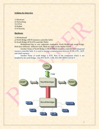
  • 1. Syllabus for Interview 1) Hardware 2) Networking 3) CCNA 4) Redhat 5) It Security Hardware 1) Motherboard a) North Bridge (MCH (memory controller hub)) b) South Bridge (ICH (I/O controller Hub)) Motherboard has to very important component North Bridge and south bridge. Both have different –different work. Both are chips on the mother board. Another Name of North Bridge is MCH/IMCH (memory controller hub/integrated memory controller hub). It is used to manage communication between RAM, CPU, AGP, and chach memory. Another Name of south bridge is ICH. Rest of the component which is not handled by the north bridge. Like PCI SLOT, USB, ISA IDE BIOS LEGACY. 1
  • 2. ZERO LEVEL FORMATTING 1) For Zero level formatting you have to insert windows 98 cd in cdrom and restart system boot via cd rom 2) You find command prompt and go to cd rom 3) A:> G: suppose A is default prompt and G is 98 prompt 4) G:> dir 5) G:>cd Dm 6) G:DM>dir 7) G:DM>cd DmSam 8) G:DMDMSAM>DIR 9) G:DMDMSAM>DM /X/M RAID (redundant array of independent disks; originally redundant array of inexpensive disks) RAID is a way of storing the same data in different places (thus, redundantly) on multiple hard disk . By placing data on multiple disks, I/O (input/output) operations can overlap in a balanced way, improving performance.  RAID-0: This technique has striping but no redundancy of data. It offers the best performance but no fault-tolerance.  RAID-1: This type is also known as disk mirroring and consists of at least two drives that duplicate the storage of data. There is no striping. Read performance is improved since either disk can be read at the same time. Write performance is the same as for single disk storage. RAID-1 provides the best performance and the best fault-tolerance in a multi-user system.  RAID-2: This type uses striping across disks with some disks storing error checking and correcting (ECC) information. It has no advantage over RAID-3.  RAID-3: This type uses striping and dedicates one drive to storing parity information. The embedded error checking (ECC) information is used to detect errors. Data recovery is accomplished by calculating the exclusive OR (XOR) of the information recorded on the other drives. Since an I/O operation addresses all drives at the same time, RAID-3 cannot overlap I/O. For this reason, RAID-3 is best for single-user systems with long record applications.  RAID-4: This type uses large stripes, which means you can read records from any single drive. This allows you to take advantage of overlapped I/O for read operations. Since all write operations have to update the parity drive, no I/O overlapping is possible. RAID-4 offers no advantage over RAID-5.  RAID-5: This type includes a rotating parity array, thus addressing the write limitation in RAID-4. Thus, all read and write operations can be overlapped. RAID-5 stores parity information but not redundant data (but parity information 2
  • 3. can be used to reconstruct data). RAID-5 requires at least three and usually five disks for the array. It's best for multi-user systems in which performance is not critical or which do few write operations.  RAID-10: Combining RAID-0 and RAID-1 is often referred to as RAID-10, which offers higher performance than RAID-1 but at much higher cost. There are two subtypes: In RAID-0+1, data is organized as stripes across multiple disks, and then the striped disk sets are mirrored. In RAID-1+0, the data is mirrored and the mirrors are striped. Small Computer System Interface (SCSI) Internal memory Ram (Random access memory) Rom (Read only memory) 1. ROM - Read Only Memory 2. PROM - Programmable Read Only Memory 3. EPROM - Erasable Programmable Read Only Memory (UV RAYS) 4. EEPROM - Electrically Erasable Programmable Read Only Memory (high voltage of electric) 5. Flash EEPROM memory BIOS=It stands for Basic input output system. It is also known as ROM (Read Only Memory). It is the boot firmware program on a PC, and controls the computer from the time you start it up until the operating system takes over. When you turn on a PC, the BIOS first conduct a basic hardware check, called a Power-On Self Test (POST), to determine whether all of the attachments are present and working. Then it loads the operating system into your computer's random access memory, or RAM. The BIOS also manages data flow between the computer's operating system and attached devices such as the hard disk, video card, keyboard, mouse, and printer. The BIOS stores the date, the time, and your system configuration information in a battery-powered, non-volatile memory chip, called a CMOS (Complementary Metal Oxide Semiconductor) after its manufacturing process. Although the BIOS is standardized and should rarely require updating, some older BIOS chips may not accommodate new hardware devices. Before the early 1990s, you couldn't update the BIOS without removing and replacing its ROM chip. Contemporary BIOS resides on memory chips such as flash chips or EEPROM (Electrically Erasable Programmable Read-Only Memory), so that you can update the BIOS yourself if necessary. POST= It stands of Power on self test. The POST is a test the computer must complete to verify all hardware is working properly before starting the remainder of the boot process. If the computer passes the POST the computer will often return a single beep and if unsuccessful will create a beep code that indicates the error. 3
  • 4. Networking What is network? A network consists of two or more computers that are linked in order to share resources (such as printers and CDs), exchange files, or allow electronic communications. The computers on a network may be linked through cables, telephone lines, radio waves, satellites, or infrared light beams. Wired and wireless both are called communication media. Communication media – there are two types of communication media. 1) Wired 2) Wireless 1) Wired- in wired communication media Angina three types A) Coaxial cable (connector BNC=births novel connector) I) thin net coaxial cable (RG 58) ii) Thick net coaxial cable (RG 8) B) Twisted pair cable (RJ45) I) UTP (unshielded twisted pair cable) ii) STP (shielded twisted pair cable) c) Fiber optic cable (SC=subscriber connector, ST=straight tip connector) i) Single mode fiber optic cable ii) Multimode fiber optic cable Some important terms of networking -: 1) MAC Address 2) IP Address 3) NIC 4) HUB 5) SWITCH 6) ROUTER 7) BRIDGE 8) MODEM 9) ACCESS POINT 10) COLLISION DOMAIN 11) BROADCAST DOMAIN 12) VPN (VITUAL PRIVATE NETWORK) 13) NODE 14) HOST 15) FIREWALL 16) TRANSCIVER 1) MAC Address:- (Media access control) It is also known as hardware address or physical address of a devices. It is 12 digit hexadecimal number and 48 bit binary number. It is representing in hexadecimal number. Broadcast Mac address FF: FF: FF: 4
  • 5. FF: FF: FF(layer two Broadcast address). First 6 digits are manufacture id and another six digit are client id which is maintained by manufacturer. MM:MM:MM:SS:SS:SS 2) IP ADDRESS:- (Internet protocol ) It is logical address of a device . It is 32 bit binary number which is represent in decimal format and it is divided into 4 octets and each octet is separated by each other by dot (.). In a single network any ip address should not be same otherwise ip conflicted error will come. Broadcast Ip address 255.255.255.255 (layer three Broadcast address). 3) NIC:-It stands for network interface card . In computer networking, a NIC provides the hardware interface between a computer and a network. A NIC technically is network adapter hardware in the form factor of an add-in card such as a PCI or PCMCIA card. This is the card that physically makes the connection between the computer and the network cable. 4) HUB:- Hub is a network connectivity device and it is work on layer one of osi model devices. It is work in half duplex mode. Hub received data packet from a computer and Broadcast it to all devices. In a hub one collision domain and one broadcast domain. Collision domains are found in a hub environment where each host segment connects to a hub that represents only one collision domain and only one broadcast domain. Collision domains are also found in wireless network such as wi-fi. 5) SWITCH:-Switch is also network connectivity devices; it is work on layer two of osi model. It works on full duplex mode. A switch has 1 collision domain per interface. And one broadcast domain. Switch create Mac table by using hardware chip ASIC (Application Specific Integrated Circuit) 6) ROUTER:- A router is a internet work connectivity device that is used to communicate one network to another network. Routers operate at the network layer (OSI Model's layer 3). The primary function of a router is to connect networks together and keep certain kinds of broadcast traffic under control. There are several companies that make routers: Cisco (Linksys), Juniper, Nortel (Bay Networks), Redback, Lucent, 3com, and HP just to name a few. Restrict network broadcasts to the LAN Act as the default gateway. Move data between networks Learn and advertise loop free paths Router works two types of protocol Routed and Routing protocol. A routed protocol can be routed by a router, which means that it can be forwarded from one router to another. A routed protocol contains the data elements required for a packet to be sent outside of its host network or network segment. In other words, a routed protocol can be routed. Routed protocols are IP and IPX. Routing protocol select the best path for packet transmission of remote network. example rip eigrp ospf is routing protocol. 5
  • 6. 7) BRIDGE:-It is used to connect two different network segment in a Lan. A bridge device filters data traffic at a network boundary. Bridges reduce the amount of traffic on a LAN by dividing it into two segments. Bridges operate at the data link layer (Layer 2) of the OSI model. Bridges inspect incoming traffic and decide whether to forward or discard it. An Ethernet bridge, for example, inspects each incoming Ethernet frame - including the source and destination MAC addresses, and sometimes the frame size - in making individual forwarding decisions. 8) MODEM:- It is called modulator-demodulator. It is convert digital signals into analog signals it is called modulation and transmits it. At the receiving end angina it convert analog signal into digital signal it is called demodulation. 9) ACCESS POINT :- Wireless access points (APs or WAPs) are specially configured nodes on wireless local area networks (WLANs). Access points act as a central transmitter and receiver of WLAN radio signals.Access points used in home or small business networks are generally small, dedicated hardware devices featuring a built-in network adapter, antenna, and radio transmitter. Access points support Wi-Fi wireless communication standards. 10) COLLISION DOMAIN:- A collision domain is an area on the network where two devices may attempt to transmit at the same time. A hub has 1 collision domain overall. A switch has 1 collision domain per interface. 11) BROADCAST DOMAIN:- A broadcast domain is a logical division of a computer network, in which all nodes can reach each other by broadcast at the data link layer. A broadcast domain can be within the same LAN segment or it can be bridged to other LAN segments. In a switch one broadcast domain. If any switch has 12 ports then one Broadcast domain and 12 collision domain in it. If any hub has 12 ports then single collision domain and single broadcast domain. 12)VPN:- A Virtual Private Network (VPN) is a network technology that creates a secure network connection over a public network such as the Internet or a private network owned by a service provider. Large corporations, educational institutions, and government agencies use VPN technology to enable remote users to securely connect to a private network. 13) NODE:- In networks, a processing location. A node can be a computer or some other device, such as a printer. Every node has a unique network address, sometimes called a Data Link Control (DLC) address or Media Access Control (MAC) address. A node can be a computer and terminal and any other devices. 14) HOST:-In a computer network host has a unique ip address. And it has some data. A computer that is connected to a TCP/IP network, including the Internet. Each host has a unique IP address. 6
  • 7. 15) FIREWALL:-Firewall is both hardware and software devices. A system designed to prevent unauthorized access to or from a private network. Firewalls can be implemented in both hardware and software, or a combination of both. Firewalls are frequently used to prevent unauthorized Internet users from accessing private networks connected to the Internet, especially internet. All messages entering or leaving the intranet pass through the firewall, which examines each message and blocks those that do not meet the specified security criteria. 16) TRANSCIVER =Network Transceivers, short for transmitter-receiver, are devices that both transmit and receive analog or digital signals. The term is used most frequently to describe the component in a local-area network (LAN) that actually applies signals onto the network wire and also detects signals passing through the same wire. For many LANs, the transceiver is built directly into the network interface card (NIC). Some types of networks, however, require an external transceiver. Network transceivers are available in three main configurations: chip, board, or module style. Chip style network transceivers are the smallest type. They can easily be inserted into or removed from a network system. Board style devices are built directly into a network board or card. Module transceivers are external to the network, and are installed and function similarly to other computer peripherals, or they may function as stand-alone devices. TYPES OF NETWORK: Basically there are three types of network:- 1) LAN 2) WAN 3) MAN 1) LAN:-LAN stands for local area network. It is a computer network which is connoted with each other and shair their resources and information but not connected to the internet is called LAN. 2) WAN:-WAN stands for wide are network. A WAN spans a large geographic area, such as a state, province or country. WANs often connect multiple smaller networks, such as local area networks (LANs) or metro area networks (MANs). The world's most popular WAN is the Internet. Some segments of the Internet, like VPN- based extranets, are also WANs in themselves. Finally, many WANs are corporate or research networks that utilize leased lines. WANs generally utilize different and much more expensive networking equipment than do LANs. Key technologies often found in WANs include SONET, Frame Relay, and ATM. 3)MAN:- Man stand for Metropolitan area network. A network spanning a physical area larger than a LAN but smaller than a WAN, such as a city. A MAN is typically owned an operated by a single entity such as a government body or large corporation. 7
  • 8. NETWORK MODEL:- There are three types of network model 1) Peer to peer 2) Server client 3) Central computing 1) PEER TO PEER =Peer-to-peer (abbreviated to P2P) refers to a computer network in which each computer in the network can act as a client or server for the other computers in the network, allowing shared access to files and peripherals without the need for a central server. P2P networks can be set up in the home, a business or over the Internet. Each network type requires all computers in the network to use the same or a compatible program to connect to each other and access files and other resources found on the other computer. P2P networks can be used for sharing content such as audio, video, data or anything in digital format. 2) SERVER CLIENT =The client/server model is a computing model that acts as distributed application which partitions tasks or workloads between the providers of a resource or service, called servers, and service requesters, called clients. Often clients and 8
  • 9. servers communicate over a computer network on separate hardware, but both client and server may reside in the same system. A server machine is a host that is running one or more server programs which share their resources with clients. A client does not share any of its resources, but requests a server's content or service function. Clients therefore initiate communication sessions with servers which await incoming requests. 3) CENTRAL COMPUTING =Centralized computing is computing done at a central location, using terminals that are attached to a central computer. The computer itself may control all the peripherals directly (if they are physically connected to the central computer), or they may be attached via a terminal server. Alternatively, if the terminals have the capability, they may be able to connect to the central computer over the network. The terminals may be text terminals or thin clients, for example. In this type of model a machine process all the data and other computer in network work like as dump terminal they can only provide the input and see the output. NETWORK TOPOLOGYES - The specific physical, i.e., real, or logical, i.e., virtual, arrangement of the elements of a network. Note 1: Two networks have the same topology if the connection configuration is the same, although the networks may differ in physical interconnections, distances between nodes, transmission rates, and/or signal types. Note 2: The common types of network topology are illustrated and defined in alphabetical order below. There are two type of network topology. 1) logical and 2) physical topology . 9
  • 10. 1)LOGICAL TOPOLOGY =Logical topology (also referred to as signal topology) is a network computing term used to describe the arrangement of devices on a network and how they communicate with one another. Logical topologies are bound to network protocols and describe how data is moved across the network. There are attempts to study the logical topology of the Internet by network scientists such as Albert-László Barabási. 2) PHYSICL TOPOLOGY =The shape of the cabling layout used to link devices is called the physical topology of the network. This refers to the layout of cabling, the locations of nodes, and the interconnections between the nodes and the cabling. The physical topology of a network is determined by the capabilities of the network access devices and media, the level of control or fault tolerance desired, and the cost associated with cabling or telecommunications circuits. 1. Bus Topology 2. Star Topology 3. Ring Topology 4. Mesh Topology --> Full Mesh --> Partial Mesh 5. Tree Topology 6. Hybrid Topology 1)BUS TOPOLOGY =In local area networks where bus topology is used, each node is connected to a single cable. Each computer or server is connected to the single bus cable. And it is terminated at both ends. bus topology consists of only one wire, it is rather inexpensive to implement when compared to other topologies. However, the low cost of implementing the technology is offset by the high cost of managing the network. Additionally, since only one cable is utilized, it can be the single point of failure. If the network cable is terminated on both ends and when without termination data transfer stop and when cable breaks, the entire network will be down. Advantages: A)Failure of one of the station does not affect others. B)Good compromise over the other two topologies as it allows relatively high rate of data tansmittion. C)Well suited for temporary networks that must be set up in a hurry. D)Easy to implement and extend. Disadvantage: A)Require a network to detect when two nodes are transmitting at the same time. B)Does not cope well with heavy traffic rates C)Difficult to administer/troubleshoot. E)Limited cable length and number of stations. F)A cable brake can disable the entire network; no redundancy. G)Maintenance cost may be higher in the long run. H)Performance degrade as additional computers are added. 10
  • 11. 2) STAR TOPOLOGY =In local area networks with a star topology, In Star topology, all the components of network are connected to the central device called ―hub‖ which may be a hub, a router or a switch. Unlike Bus topology (discussed earlier), where nodes were connected to central cable, here all the workstations are connected to central device with a point-to-point connection. So it can be said that every computer is indirectly connected to every other node by the help of ―hub, Switch‖. All the data on the star topology passes through the central device before reaching the intended destination. Hub acts as a junction to connect different nodes present in Star Network, and at the same time it manages and controls whole of the network. Depending on which central device is used, ―hub‖ can act as repeater or signal booster. Central device can also communicate with other hubs of different network. Unshielded Twisted Pair (UTP) Ethernet cable is used to connect workstations to central node. Advantages : 1)New system can be added easily and quickly. 2)A single cable fail no break down entire network. 3)It is easy to troubleshoot. Disadvantages : 1)It is costly because of large amount of cable is required. 2)It has single point of fail ( Hub, Switch and Access Point) 3) RING TOPOLOGY =In Ring Topology, all the nodes are connected to each-other in such a way that they make a closed loop. Each workstation is connected to two other components on either side, and it communicates with these two adjacent neighbors. Data travels around the network, in one direction. Sending and receiving of data takes place by 11
  • 12. the help of TOKEN. Token Passing (in brief) : Token contains a piece of information which along with data is sent by the source computer. This token then passes to next node, which checks if the signal is intended to it. If yes, it receives it and passes the empty to into the network, otherwise passes token along with the data to next node. This process continues until the signal reaches its intended destination. The nodes with token are the ones only allowed to send data. Other nodes have to wait for an empty token to reach them. This network is usually found in offices, schools and small buildings. RING AND TOKEN RING Advantages of Ring Topology 1) This type of network topology is very organized. Each node gets to send the data when it receives an empty token. This helps to reduces chances of collision. Also in ring topology all the traffic flows in only one direction at very high speed. 2) Even when the load on the network increases, its performance is better than that of Bus topology. 3) There is no need for network server to control the connectivity between workstations. 4) Additional components do not affect the performance of network. 5) Each computer has equal access to resources. Disadvantages of Ring Topology 1) Each packet of data must pass through all the computers between source and destination. This makes it slower than Star topology. 2) If one workstation or port goes down, the entire network gets affected. 12
  • 13. 3) Network is highly dependent on the wire which connects different components. 4) MAU‘s and network cards are expensive as compared to Ethernet cards and hubs. 4) MASH TOPOLOGY =In a mesh network topology, each of the network node, computer and other devices, are interconnected with one another. Every node not only sends its own signals but also relays data from other nodes. In fact a true mesh topology is the one where every node is connected to every other node in the network. This type of topology is very expensive as there are many redundant connections, thus it is not mostly used in computer networks. It is commonly used in wireless networks. Flooding or routing technique is used in mesh topology. Types of Mesh Network topologies:- 1)FULL MESH TOPOLOGY: In this, like a true mesh, each component is connected to every other component. Even after considering the redundancy factor and cost of this network, its main advantage is that the network traffic can be redirected to other nodes if one of the nodes goes down. Full mesh topology is used only for backbone networks. 2)PARTIAL MESH TOPOLOGY: This is far more practical as compared to full mesh topology. Here, some of the systems are connected in similar fashion as in mesh topology while rests of the systems are only connected to 1 or 2 devices. It can be said that in partial mesh, the workstations are ‗indirectly‘ connected to other devices. This one is less costly and also reducesredundancy. Mesh Topology Diagram Advantages of Mesh topology 1) Data can be transmitted from different devices simultaneously. This topology can withstand high traffic. 2) Even if one of the components fails there is always an alternative present. So data transfer doesn‘t get affected. 13
  • 14. 3) Expansion and modification in topology can be done without disrupting other nodes. Disadvantages of Mesh topology 1) There are high chances of redundancy in many of the network connections. 2) Overall cost of this network is way too high as compared to other network topologies. 3) Set-up and maintenance of this topology is very difficult. Even administration of the network is tough. 5) TREE TOPOLOGY = Tree Topology integrates the characteristics of Star and Bus Topology. Earlier we saw how in Physical Star network Topology, computers (nodes) are connected by each other through central hub. And we also saw in Bus Topology, work station devices are connected by the common cable called Bus. After understanding these two network configurations, we can discuss tree topology better. In Tree Topology, the number of Star networks are connected using Bus. This main cable seems like a main stem of a tree, and other star networks as the branches. It is also called Expanded Star Topology. Ethernet protocol is commonly used in this type of topology. The diagram below will make it clear. Advantages of Tree Topology 1. It is an extension of Star and bus Topologies, so in networks where these topologies can't be implemented individually for reasons related to scalability, tree topology is the best alternative. 2. Expansion of Network is possible and easy. 3. Here, we divide the whole network into segments (star networks), which can be easily managed and maintained. 4. Error detection and correction is easy. 5. Each segment is provided with dedicated point-to-point wiring to the central hub. 6. If one segment is damaged, other segments are not affected. Disadvantages of Tree Topology 1. Because of its basic structure, tree topology, relies heavily on the main bus cable, if it breaks whole network is crippled. 2. As more and more nodes and segments are added, the maintenance becomes difficult. 3. Scalability of the network depends on the type of cable used. 14
  • 15. 6) HYBRIDE TOPOLOGY = Before starting about Hybrid topology, we saw that a network topology is a connection of various links and nodes, communicating with each other for transfer of data. We also saw various advantages and disadvantages of Star, Bus, Ring, Mesh and Tree topologies. Now lets discuss what Hybrid Network topology is and why it finds its application in Wide Area Networks. Hybrid, as the name suggests, is mixture of two different things. Similarly in this type of topology we integrate two or more different topologies to form a resultant topology which has good points(as well as weaknesses) of all the constituent basic topologies rather than having characteristics of one specific topology. This combination of topologies is done according to the requirements of the organization. For example, if there exists a ring topology in one office department while a bus topology in another department, connecting these two will result in Hybrid topology. Remember connecting two similar topologies cannot be termed as Hybrid topology. Star-Ring and Star-Bus networks are most common examples of hybrid network. Let's see the benefits and drawbacks of this networking architecture Hybrid Network Topology Image Advantages of Hybrid Network Topology 1) Reliable : Unlike other networks, fault detection and troubleshooting is easy in this type of topology. The part in which fault is detected can be isolated from the rest of network and required corrective measures can be taken, WITHOUT affecting the functioning of rest of the network. 2) Scalable: Its easy to increase the size of network by adding new components, without disturbing existing architecture. 3) Flexible: Hybrid Network can be designed according to the requirements of the organization and by optimizing the available resources. Special care can be given to 15
  • 16. nodes where traffic is high as well as where chances of fault are high. 4) Effective: Hybrid topology is the combination of two or more topologies, so we can design it in such a way that strengths of constituent topologies are maximized while there weaknesses are neutralized. For example we saw Ring Topology has good data reliability (achieved by use of tokens) and Star topology has high tolerance capability (as each node is not directly connected to other but through central device), so these two can be used effectively in hybrid star-ring topology. Disadvantages of Hybrid Topology 1) Complexity of Design: One of the biggest drawback of hybrid topology is its design. Its not easy to design this type of architecture and its a tough job for designers. Configuration and installation process needs to be very efficient. 2) Costly Hub: The hubs used to connect two distinct networks, are very expensive. These hubs are different from usual hubs as they need to be intelligent enough to work with different architectures and should be function even if a part of network is down. 3) Costly Infrastructure: As hybrid architectures are usually larger in scale, they require a lot of cables, cooling systems, sophisticate network devices, etc. CABLES (PHYSICAL MEADIA) There are three types of cable 1) COAXIAL CABLE 2) TWISTED PAIR CABLE 3) FIBER OPTIC CABLE 1) COAXIAL CABLE = A type of wire that consists of a center wire surrounded by insulation and then a grounded shield of braided wire. The shield minimizes electrical EMI (Electromagnetic interference) and radio frequency interference. Coaxial cabling is the primary type of cabling used by the cable television industry and is also widely used for computer networks, such as Ethernet. Although more expensive than standard telephone wire, it is much less susceptible to interference and can carry much more data. There two types of coaxial cable:- A) Tinnet coaxial cable( RG58) B) Tick net coaxial cable (RG 8) 16
  • 17. CABLE = TINNET CABLE = TICK NET 10 BASE 2 10 BASE 2 SINGNAL = BASEBAND / DIGITAL SINGNAL = BASEBAND/DIGITAL SPEED = 10 MBPS SPEED = 10 MBPS LENGTH = 18.5 METER LENGTH =500 METERS CONNECTOR = BNC CONNECTOR = AUI, VAMPIRE DIAMETER = 0.25 CM DIAMETER = 0.96 CM BNC =British novel connector AUI = Attachment User interface RG = Radio Government 2) TWISTED PAIR CABLE= A type of cable that consists of two independently insulated wires twisted around one another. The use of two wires twisted together helps to reduce crosstalk and electromagnetic induction. While twisted-pair cable is used by older telephone networks and is the least expensive type of local-area network (LAN) cable, most networks contain some twisted-pair cabling at some point along the network. Connector RJ45, RJ11. RJ stands for Register jack. There are two types of Twisted Pair Cable 1) UTP (UNSHIELDED TWISTED PAIR CABLE) 2) STP (SHIELDED TWISTED PAIR CABLE) 1) UTP = UTP stands for Unshielded Twisted Pair cable. UTP cable is a 100 ohm copper cable that consists of 2 to 1800 unshielded twisted pairs surrounded by an outer jacket. They have no metallic shield. This makes the cable small in diameter but unprotected against electrical interference. The twist helps to improve its immunity to electrical noise and EMI. 2) STP= a type of copper telephone wiring in which each of the two copper wires that are twisted together are coated with an insulating coating that functions as a ground for the wires. The extra covering in shielded twisted pair wiring protects the transmission line from electromagnetic interference leaking into or out of the cable. STP cabling often is used in Ethernet networks, especially fast data rate Ethernets. 17
  • 18. CROSSOVER CABLE COLOR CODDIGN 13 26 FIRST END LAST END T568B T568A ORANGE-WHITE GREEN –WHITE ORANGE GREEN GREEN WHITE ORANGE-WHITE BLUE BLUE BLUE-WHITE BLUE-WHITE GREEN ORANGE BROWN-WHITE BROWN-WHITE BROWN BROWN CROSS CABLE USE:- 13 AND 26 FIRST END =T568B AND SECOND END = T568A IT is used to connect similar devices like PC to PC, HUB TO HUB, SWITCH TO SWITCH and ROUTER TO PC. STRIGHT THROUGH CABLE:- FIRST END =T568B AND SECOND END T568B It is used to connect dissimilar devices like pc to hub, switch to pc, ROUTER TO SWITCH, MODEM TO PC , SWITCH TO MODEM ROLLEDOVER CABLE:- It is used to connect router‘s console port to pc . And router‘s console port is used to configure router. First end =T568B and second end= just opposite T568B 18
  • 19. 3) FIBER OPTIC CABLE =Fiber Optic Cable Transmit digital signals using the light impulse rather then analog signals. It is save from EMI. Optical fiber consists of a core and a cladding layer, selected for total internal reflection due to the difference in the refractive between the two. In practical fibers, the cladding is usually coated with a layer of acrylate polymer or polyimide. This coating protects the fiber from damage but does not contribute to its optical waveguide properties. Individual coated fibers (or fibers formed into ribbons or bundles) then have a tough resin buffer layer and/or core tube(s) extruded around them to form the cable core. Several layers of protective sheathing, depending on the application, are added to form the cable. Rigid fiber assemblies sometimes put light-absorbing ("dark") glass between the fibers, to prevent light that leaks out of one fiber from entering another. This reduces cross-talk between the fibers, or reduces flare in fiber bundle imaging applications. There are two types of Fiber optic cable- A)Single Mode Fiber Optic Cable B) Multi Mode Fiber Optic Cable Single Mode Fiber Optic Cable can transmit only single light rays while multimode Fiber optic cable can transmit multiple light Signal. Multimode Fiber optic cable is used for short distance application and Single mode fiber optic cable is used for long distance Fiber optic cable can transmit up to 40 Kilometers . It support bandwidth 100Mbps 1Gbps and 10Gbps. Connectors for Fiber Optic cable ST(straight Tip) and SC(Subscriber Connector) and the SC connector is developed by AT&T. Fiber optic cable is very costly and it is difficult to install, it is required a bigger investment in installation. 19
  • 20. Wi-Fi: - Wi-Fi is a popular technology that allows an electronic device to exchange data wirelessly (using radio wave) over a computer network, including high- speed Internet connections. IEEE STANDRAD 802.11 PROTOCOL: - A uniform set of rules that enable two devices to connect and transmit data to one another. Protocols determine how data are transmitted between computing devices and over networks. They define issues such as error control and data compression methods. OSI (OPEN SOURCE INTERCONNECTION) MODEL OSI model is seven layer conceptual models that define the communication method of computer network. It defines the communication process in 7 layers. OSI model was developed by ISO (international standard organization) in 1977(in some web site it should be 1984 1980 and 1974). First network is developed by IBM and it works only IBM devices. That‘s by OSI model was develop that a common platform can be given to all devices that dissimilar devices can communicate. Seven Layer of OSI model :- 20
  • 21. 1) PHYSICAL LAYER 2) DATA LINK LAYER 3) NETWORK LAYER 4) TRANSPORT LAYER 5) SESSION LAYER 6) PRESENTATION LAYER 7) APPLICATION LAYER The upper layers (application, presentation and session) of the OSI model represent software that implements network services like encryption and connection management. The lower layers (transport, network, data link and physical) of the OSI model implement more primitive, hardware-oriented functions like routing, addressing, and flow control.You can remember OSI layer by All People Seem To Need Data Processing. LAYER 1- PHYSICAL LAYER:- It is layer first of OSI model. Physical layer defines the cable or physical medium itself, e.g., thinnet, thicknet, unshielded twisted pairs (UTP). All media are functionally equivalent. The main difference is in convenience and cost of installation and maintenance. It define electrical and optical signaling, voltage levels, data transmission rate, as well as mechanical specifications such as cable lengths and connectors, the amount of pins and their Functions. Converters from one media to another operate at this level. Data unit = bit Devices = Hub, Repeater, cable, connectors, NICs, WAPs, LAN, WAN, Interface such as RS-232 ,OC-3, BRI And Antennas. It received data from data link layer in the form of Frame then converts it into bit. LAYER 2- DATA LINK LAYER:- It is second layer of OSI model Data Unit = Frame Devices = Switch, Bridge Protocol = STP, VTP, HDLC, PPP, FRAM RELAY. It takes data from network layer in the form of Packet than attached header and trailer on this packet now it becomes frame. Its header has the information about source Mac, destination Mac, Ether type, ant it trailer has information about FCS. FCS=FCS apply algorithm on data and generate 4Byte code and at the receiving end Again FCS apply Algorithm and Generate 4 Byte code. If code is same then no error and no modification while transmission otherwise again send data it gives flow control. The Maximum Transmission Unit (MTU). The data link layer handles the physical and logical connections to the packet's destination, using a network interface. A host connected to an Ethernet would have an Ethernet interface to handle connections to the outside world, and a loop back interface to send packets to it. Layer two Broadcast address FF:FF:FF:FF:FF:FF . 802.5 For token ring TWO sub layer of data link layer is- A) LLC(logical link control layer) B) MAC(media access control layer) 21
  • 22. A) LLC= The uppermost sub layer, LLC, multiplexes protocols running a top the data link layer (Network layer), and optionally provides flow control, acknowledgment, and error notification. The LLC provides addressing and control of the data link. It specifies which mechanisms are to be used for addressing stations over the transmission medium and for controlling the data exchanged between the originator and recipient machines. Standard 802.2 B)MAC=MAC may refer to the sub layer that determines who is allowed to access the media at any one time (usually CSMA/CD). Other times it refers to a frame structure with MAC addresses inside. There are generally two forms of media access control: distributed and centralized. Both of these may be compared to communication between people. In a network made up of people speaking, i.e. a conversation, we look for clues from our fellow talkers to see if any of them appear to be about to speak. If two people speak at the same time, they will back off and begin a long and elaborate game of saying "no, you first". The Media Access Control sub layer also determines where one frame of data ends and the next one starts – frame synchronization. There are four means of frame synchronization: time based, character counting, byte stuffing and bit stuffing. IEEE Standers Of data link (MAC Sublayer) layer 802.3,802.4,802.5 and 802.11. 22
  • 23. LAYER3-NETWORK LAYER It is layer 3 of OSI model Data Unit = Packet Devices =Router Protocol= Routed and Routing Protocol Layer three Broadcast address 255.255.255.255 Routed Protocol=It is define the method of Packet Transmission in Internetwork Example =IP, IPx, AppleTalk Routing Protocol=It select the best path for packet Transmission example RIP IGRP EIGRP OSPF. It received data from transport layer in the form of segment then attach header on segment now it become packet. Its header has information about source ip address and destination ip address. Router understands the ip address and it creates routing tables. Routing tables has information about best path for packet transmission. The network layer is the layer at which IP (Internet protocol) operates. Other protocols in the TCP/IP suite of protocols, which forms the basis of the Internet and most other networks, that also operate in this layer are ICMP, IPsec, ARP, RIP, OSPF and BGP.The network layer is responsible for routing, which is moving packets (the fundamental unit of data transport on modern computer networks) across the network using the most appropriate paths. It also addresses messages and translates logical addresses (i.e., IP addresses) into physical addresses (i.e., MAC addresses). LAYER4-TRANSPORT LAYER It is layer 4 of OSI model Data Unit = Segment Protocol = TCP, UDP 23
  • 24. It received data from session layer in the form of data and divided it into segments, Each and every segment has a header, its header has information about source port no, destination port no, sequence no and Acknowledgement number and window etc. The Transport layer is responsible for end-to-end (source-to-destination) data delivery. The Transport layer ensures the reliable arrival of messages and provides error checking mechanisms and data flow controls. The Transport layer provides services for both "connection-mode" transmissions and for "connectionless-mode" transmissions. For connection-mode transmissions, a transmission may be sent or arrive in the form of packets that need to be reconstructed into a complete message at the other end. Header format of Transport Layer LAYER 5- SESSION LAYER It is fifth layer of OSI model Data Unit = Data It creates session between different communication process and it is responsible for the mechanism for opening, closing and managing a session between end-user application processes, i.e., a semi-permanent dialogue. Communication sessions consist of requests and responses that occur between applications. Session-layer services are commonly used in application environments that make use of remote procedure 24
  • 25. calls (RPCs). These layers also provide the dialog control between devices or nodes. It is also control communication mode. Three are three types of communication mode. A) Simplex B) Half Duplex C) Full Duplex A) Simplex =In simplex operation, a network cable or communications channel can only send information in one direction; it's a ―one-way street‖. In simple way only one way communication. B) Half Duplex=A half-duplex (HDX) system provides communication in both directions, but only one direction at a time (not simultaneously). Typically, once a party begins receiving a signal, it must wait for the transmitter to stop transmitting, before replying (antennas are of trans-receiver type in these devices, so as to transmit and receive the signal as well). Example cordless, Hub. C) Full Duplex= A full-duplex (FDX), or sometimes double-duplex system, allows communication in both directions, and, unlike half-duplex, allows this to happen simultaneously. Land-line telephone networks are full-duplex, since they allow both callers to speak and be heard at the same time. A good analogy for a full-duplex system would be a two-lane road with one lane for each direction. Example mobile call, Switch. LAYER 6-PRESENTATION LAYER It is layer 6 th of OSI model. Data Unit=data The Presentation layer ‗represent‘ the data in particular format of The Application layer. It defines encryption, Compression, Conversion and coding Function. Data are passed from the application layer services. These data must then be formatted into agreed-upon codes. The codes can be alphanumeric, numeric, video, audio, or program instruction codes. The presentation layer may also be responsible for data compression and encryption. The three most common types of translation methods are bit order, byte order, and character code translation. Encryption services provided by the OSI presentation layer protocols include transposition, substitution, and algebraic methods ENCRIPTION = Encryption is the conversion of data into a form, called a cipher text, that cannot be easily understood by unauthorized people. Decryption is the process of converting encrypted data back into its original form, so it can be understood able. COMPRESSION= Compression is the process of reducing the size of a file by encoding its data information more efficiently. By doing this, the result is a reduction in the number of bits and bytes used to store the information. In effect, a smaller file size is generated in order to achieve a faster transmission of electronic files and a smaller space required for its downloading. TRANSLATION= The presentation layer serves as the data translator for the network. This layer on the sending computer translates the data sent by the application layer into a 25
  • 26. common format. At the receiving computer, the presentation layer translates the common format to a format known to the application layer. Character-code translation, such as from ASCII to EBCDIC. LAYER 7- APPLICATION LAYER It is layer 7 of OSI model Data Unit = data Protocol = Http, Telnet, Ftp, Tftp, Smtp, Ntp The application layer provider different services to the application. Examples of services provided by this layer are file transfer, electronic messaging e-mail, virtual terminal access and network management. Data is often encoded using different schemes, such as ASCII, EBCIDC or UNICODE. It is provide interface for different Application like ms- word, ms-outlook, Http. ASCII = American standard code for information interchange EBCIDC= Extended binary coded decimal interchange code UNICODE= Unique Universal and Uniform character encoding Types of Transmission Unicast Unicast packets are sent from host to host. The communication is from a single host to another single host. There is one device transmitting a message destined for one receiver. In simple word one to one communication. Broadcast 26
  • 27. Broadcast is when a single device is transmitting a message to all other devices in a given address range. This broadcast could reach all hosts on the subnet, all subnets, or all hosts on all subnets. Broadcast packets have the host (and/or subnet) portion of the address set to all ones. By design, most modern routers will block IP broadcast traffic and restrict it to the local subnet. In word one to all communication. Multicast Multicast is a special protocol for use with IP. Multicast enables a single device to communicate with a specific set of hosts, not defined by any standard IP address and mask combination. This allows for communication that resembles a conference call. Anyone from anywhere can join the conference, and everyone at the conference hears what the speaker has to say. The speaker's message isn't broadcasted everywhere, but only to those in the conference call itself. A special set of addresses is used for multicast communication. In simple word One to many communication. TYPES OF SWITCHING PACKET SWITCHING= Packet-switched networks move data in separate, small blocks -- packets -- based on the destination address in each packet. When received, packets are reassembled in the proper sequence to make up the message. Packet-switched networks handled data. CIRCUIT SWITCHING=Circuit-switched networks require dedicated point-to-point connections during calls. Circuit-switched networks and packet-switched networks have traditionally occupied different spaces within corporations. Circuit-switched networks were used for phone calls. MESSAGE SWITCHING =Sometimes there is no need for a circuit to be established all the way from the source to the destination. Consider a connection between the users (A and D) in the figure below (i.e. A and D) is represented by a series of links (AB, BC, and CD). A connection between two systems A & D formed from 3 links For instance, when a telex (or email) message is sent from A to D, it first passes over a local connection (AB). It is then passed at some later time to C (via link BC), and from there to the destination (via link CD). At each message switch, the received message is stored, and a connection is subsequently made to deliver the message to the neighboring message switch. Message switching is also known as store-and-forward switching since the messages are stored at intermediate nodes en route to their destinations. 27
  • 28. TCP/IP MODEL TCP/IP =Transmission Control Protocol/Internet Protocol A) It is developed by DOD (Department OF Defiance) in 1970 B) It present the data integrity while means of data transmission C) It is four Layer Model The Four Layer‘s of TCP/IP The Transmission Control Protocol (TCP) is one of the core protocols of the Internet Protocol Suite. TCP is one of the two original components of the suite, complementing the Internet Protocol (IP), and therefore the entire suite is commonly referred to as TCP/IP. TCP provides reliable, ordered delivery of a stream of bytes from a program on one computer to another program on another computer. TCP is the protocol used by major Internet applications such as the World Wide Web, email, remote administration and file transfer. Other applications, which do not require reliable data stream service, may use the User Datagram Protocol (UDP), which provides a datagram service that emphasizes reduced latency over reliability. TCP/IP is a Protocol suit it means collection of protocols. TCP/IP protocols map to a four-layer conceptual model known as the DARPA model, named after the U.S. government agency that initially developed TCP/IP. The four layers of the DARPA model 1) LAYER 1 – NETWORK LAYER /LINK LAYER Link layer is the lowest layer in the Internet Protocol Suite (TCP/IP), the networking architecture of the Internet (RFC 1122, RFC 1123). It is the group of methods or protocols that only operate on a host's link. The link is the physical and logical network component used to interconnect hosts or nodes in the network and a link protocol is a suite of methods and standards that operate only between adjacent network 28
  • 29. nodes of a Local area network segment or a wide area network connection. TCP/IP and OSI, the link layer is often described as a combination of the data link layer and the physical layer in the OSI protocol stack. However, TCP/IP's layers are descriptions of operating scopes (application, host-to-host, network, and link) and not detailed prescriptions of operating procedures, data semantics, or networking technologies. RFC 1122 exemplifies that local area network protocols such as Ethernet and IEEE 802, and framing protocols such as Point-to-Point Protocol (PPP), ARP,RARP belong to the link layer. 2) LAYER 2 – INTERNET LAYER The Internet layer in the TCP/IP reference model is responsible for transferring data between the source and destination computers. The Internet layer accepts data from the Transport layer and passes the data to the Network Interface layer. The following are the functions of the Internet layer: Transmitting data to the Network Interface layer. Routing the data to the correct destination. This layer takes care of sending the data through the shortest route if more than one route is available. In addition, if a route through which a datagram is to be sent has problems, the datagram is sent through an alternate route. IP encapsulates data into IP datagram‘s, which in turn are encapsulated inside Network Interface layer frames. IP datagram‘s are the basic units of information that are passed across a Transmission Control Protocol/Internet Protocol (TCP/IP) network. The datagram header contains information, such as the source IP address and the destination IP address. The header also contains information about which protocol will receive data from IP. These protocols are the User Datagram Protocol (UDP), the Transmission Control Protocol (TCP), and ICMP. IP IPv4, IPv6, ICMP, ICMPv6, ECN, IGMP , IPsec IP DATA GRAM HEADER 29
  • 30. 3) LAYER 3- TRANSPORT LAYER The Transport layer transports data to and from the correct application. This process is known as end-to-end communication. In TCP/IP the Transport layer provides a transport service for application data. The Transport layer header includes a destination port number that identifies the destination application program on the remote machine and a source port number that identifies the application on the originating machine. In addition, the Transport layer handles error detection, can handle recovery problems, and regulates the flow of information. The way, in which the Transport layer handles error detection, the sequence of data, and flow regulation depends on which protocol is used. There are two main protocols that operate at the Transport layer, TCP and UDP. The TCP/IP protocol stack features two Transport layer protocols, TCP and UDP: Transmission Control Protocol (TCP) and User Datagram Protocol (UDP)is a transportation protocol that is one of the core protocols of the Internet protocol suite. Both TCP and UDP work at transport layer TCP/IP model and both have very different usage. Difference between TCP and UDP TCP UDP Reliability: TCP is connection-oriented Reliability: UDP is connectionless protocol. When a file or message send it will protocol. When you a send a data or get delivered unless connections fails. If message, you don't know if it'll get there, it connection lost, the server will request the could get lost on the way. There may be lost part. There is no corruption while corruption while transferring a message. transferring a message. Ordered: If you send two messages along a Ordered: If you send two messages out, you connection, one after the other, you know the don't know what order they'll arrive in first message will get there first. You don't i.e. no ordered have to worry about data arriving in the wrong order. Heavyweight: - when the low level parts of Lightweight: No ordering of messages, no the TCP "stream" arrive in the wrong order, tracking connections, etc. It's just fire and resend requests have to be sent, and all the forget! This means it's a lot quicker, and the out of sequence parts have to be put back network card / OS have to do very little together, so requires a bit of work to piece work to translate the data back from the together. packets. Streaming: Data is read as a "stream," with Datagrams: Packets are sent individually nothing distinguishing where one packet and are guaranteed to be whole if they ends and another begins. There may be arrive. One packet per one read call. multiple packets per read call. Examples: World Wide Web (Apache TCP Examples: Domain Name System (DNS port 80), e-mail (SMTP TCP port 25 Postfix UDP port 53), streaming media MTA), File Transfer Protocol (FTP port 21) applications such as IPTV or movies, Voice 30
  • 31. and Secure Shell (OpenSSH port 22) etc. over IP (VoIP), Trivial File Transfer Protocol (TFTP) and online multiplayer games etc Basic UDP information UDP is a connectionless, stateless, and unreliable protocol. It is faster and more efficient for many lightweight or time-sensitive purposes. Also, its stateless nature is useful for servers that answer small queries from huge numbers of clients. UDP is required for broadcast (send to all on local network) andmulticast (send to all subscribers). With UDP, the application is responsible for handling message loss, duplication, sequence (delivery out of order), and loss of connection. UDP receives incoming data from the application and encapsulates the data into UDP datagrams. UDP datagrams have a leading header section hat contains the source and destination port numbers, followed by the data section. 16 32 bits Source port Destination port Length Checksum Data Basic TCP Information TCP is a connection-oriented, state full , and reliable protocol. TCP is suited for situations where large volumes of data must travel between systems, particularly across multiple routers and gateways. TCP has four main features:  Virtual circuit connection  Full-duplex connection  Unstructured stream orientation  Buffered transfer The TCP segment header has more fields then UDP header. The TCP header structure is as follows: 31
  • 32. 16 32 bits Source port Destination port Sequence number Acknowledgement number Offset Reserved U A P R S F Window Checksum Urgent pointer Option + Padding Data TCP header structure 4) LAYER 4- APPLICATION LAYER In TCP/IP, the application layer contains all protocols and methods that fall into the realm of process-to-process communications across an Internet Protocol (IP) network. Application layer methods use the underlying transport layer protocols to establish host- to-host connections. In the OSI model, the definition of its application layer is narrower in scope, explicitly distinguishing additional functionality above the transport layer at two additional levels, the session layer and the presentation layer. OSI specifies strict modular separation of functionality at these layers and provides protocol implementations for each layer. Remote login category (Telnet), File transfer category (FTP, TFTP), Electronic mail category (SMTP, IMAP, POP), Support services category (DNS, RARP, BOOTP, SNMP, CMOT) 32
  • 33. APPLICATION LAYER PROTOCOLS = 1) TELNET = (PORT NO 23 /TCP) Telnet is used to access a system form remote location via command line. We can use telnet when it configures both sides. It is unsecured because it sends user name and password in plan text format. Example: - c :> telnet 192.168.1.25 2) FTP = (PORT NO 20=DATA 21=CONNETION /TCP) FTP stands for file transfer protocol. It is just not a protocol it is a program and Application that allow to access directory and files. Port number 20 is used to transfer data and port no 21 is used to maintain connection (creating, managing and establishing).this protocol is used to download and upload files. FTP is built on client-server architecture and uses separate control and data connections between the client and the server.[1] FTP users may authenticate themselves using a clear-text sign-in protocol, normally in the form of a username and password, but can connect anonymously if the server is configured to allow it. For secure transmission that hides (encrypts) your username and password, as well as encrypts the content, you can try using a client that uses SSH File Transfer Protocol. FTPS=(PORT NO DATA=989/TCP/UDP, CONTROL=990 TCP/UDP) It stands for File Transfer Protocol Secure. FTPS (also known as FTP Secure and FTP-SSL) is an extension to the commonly used File Transfer Protocol (FTP) that adds support for the Transport Layer Security (TLS) and the Secure Sockets Layer (SSL) cryptographic protocols. FTPS should not be confused with the SSH File Transfer Protocol (SFTP), an incompatible secure file transfer subsystem for the Secure Shell (SSH) protocol. It is also different from Secure FTP, the practice of tunneling FTP through an SSH connection. 3) TFTP= (PORT NO 69/UDP) Trivat File Transfer Protocol. TFTP is used to UDP that‘s by it is unsecured, unreliable. It is also used to download and upload files. It is faster then FTP. TFTP has no login feature (it does not prompt for user name and password). original versions of TFTP only allowed transferring files up to 32 megabytes in size (some newer TFTP servers remove this restriction). 4) SMTP = (PORT NO 25/TCP SMTPS=587) Simple Mail Transfer Protocol, a protocol for sending e-mail messages between servers. Most e-mail systems that send mail over the Internet use SMTP to send messages from one server to another By using MTA(Mail transfer agent); the messages can then be retrieved with an e-mail client using either POP or IMAP. In addition, SMTP is generally used to send messages from a mail client to a mail server. This is why you need to specify both the POP or IMAP server and the SMTP server when you configure your e-mail application. SMTP connections secured by SSL are known by the shorthand SMTPS, though SMTPS is not a protocol in its own right . SMTPS PORT NO 587. 33
  • 34. 5) IMAP =(PORT NO 143/TCP IMAPS=993) This protocol is used to accessing e-mail from your local server. IMAP is a client/server protocol in which e-mail is received and held for you by your Internet server. In other words, it permits a "client" email program to access remote message stores as if they were local. For example, email stored on an IMAP server can be manipulated from a desktop computer at home, a workstation at the office, and a notebook computer while traveling, without the need to transfer messages or files back and forth between these computers. IMAP over SSL (IMAPS) is assigned well-known port number 993. 6) POP = (PORT NO POP2=109/TCP, POP3=110/TCP, POP3S=995) There are two types of Post Office Protocol (POP2, POP3). Post Office Protocol (POP) is an application-layer Internet standard protocol used by local e-mail clients to retrieve e- mail from a remote server over a TCP/IP connection. POP and IMAP are the two most prevalent Internet standard protocols for e-mail retrieval. Virtually all modern e-mail clients and servers support both. The POP protocol has been developed through several versions, with version 3 (POP3) being the current standard. Most web mail service providers such as Hotmail, Email and Yahoo! Mail also provide IMAP and POP3 service. POP3 can be used with or without SMTP. Encrypted communication for POP3 is either requested after protocol initiation, using the STLS command, if supported, or by POP3S, which connects to the server using Transport Layer Security (TLS) or Secure Sockets Layer (SSL) on well-known TCP port 995 (e.g. Google Gmail). 7) DNS = (PORT NO 53 /TCP/UDP) It stands for Domain Name System. It is a database system that translates a computer's fully qualified domain name into an IP address. To send information it uses TCP, and for Zone Transfer it uses UDP for named function like to reduce the query of DNS Client. DNS server resolves Name to IP address and IP to Name. DNS automatically converts the names we type in our Web browser address bar to the IP addresses of Web servers hosting those sites. DNS implements a distributed database to store this name and address information for all public hosts on the Internet. DNS assumes IP addresses do not change (are statically assigned rather than dynamically assigned). The DNS database resides on a hierarchy of special database servers. When clients like Web browsers issue requests involving Internet host names, a piece of software called the DNS resolver (usually built into the network operating system) first contacts a DNS server to determine the server's IP address. If the DNS server does not contain the needed mapping, it will in turn forward the request to a different DNS server at the next higher level in the hierarchy. After potentially several forwarding and delegation messages are sent within the DNS hierarchy, the IP address for the given host eventually arrives at the resolver, that in turn completes the request over Internet Protocol. Internet Service Providers (ISPs) maintain their own DNS servers and use DHCP to automatically configure clients, relieving most home users of the burden of DNS configuration. Each domain name registered with NTC Hosting comes with a complete set of DNS records: A, NS, MX, which you can easily manage from the user-friendly web hosting Control Panel. Along with these records, you can easily 34
  • 35. set AAAA, TXT, SRV and CNAME records for your domain name from the Control Panel. Recursive Query = With a recursive name query , the DNS client requires that the DNS server respond to the client with either the requested resource record or an error message stating that the record or domain name does not exist. The DNS server cannot just refer the DNS client to a different DNS server. Thus, if a DNS server does not have the requested information when it receives a recursive query; it queries other servers until it gets the information, or until the name query fails. Recursive name queries are generally made by a DNS client to a DNS server, or by a DNS server that is configured to pass unresolved name queries to another DNS server, in the case of a DNS server configured to use a forwarder. Iterative Query = An iterative name query is one in which a DNS client allows the DNS server to return the best answer it can give based on its cache or zone data. If the queried DNS server does not have an exact match for the queried name, the best possible information it can return is a referral (that is, a pointer to a DNS server authoritative for a lower level of the domain namespace). The DNS client can then query the DNS server for which it obtained a referral. It continues this process until it locates a DNS server that is authoritative for the queried name, or until an error or time-out condition is met. This process is sometimes referred to as "walking the tree," and this type of query is typically initiated by a DNS server that attempts to resolve a recursive name query for a DNS client. 35
  • 36. 8) DHCP= (PORT NO 67= DHCP SERVER, 68= DHCP CLIENT /UDP) Dynamic Host Configuration Protocol enables you to automatically assign reusable IP addresses (IP address, Default Gateway, subnet mask, and DNS server IP) to DHCP clients. It use UDP services .DHCP server port no. is 67 and client port no is 68. DISCOVER: When a client is configured with the IP setting to obtain Ip address automatically. Then the client will search for DHCP server and the UDP Broadcast to the server about the DHCP discover. OFFER: DHCP Server will offers a scope of IP address available in the pool. REQUEST: In response to the offer, the Client will requests for an IP address. ACKNOWLEDGE: In response to the request, server will responds with all IP address, Mask, Gateway, DNS and wins info along with the acknowledgment packet. Technical info of DORA Process = When the term "broadcast" is used, there are two types of broadcasts: 1) Network Layer broadcast and 2) Datalink Layer broadcast. For Internet Protocol, the standard broadcast DESTINATION address is 255.255.255.255. For Ethernet, the broadcast DESTINATION address is FF:FF:FF:FF:FF:FF. You have to think of the DORA process in terms of encapsulation and decapsulation, as well as switch behavior with frames it receives. So let's say you've got two computers, a client host and a server host. The client host is the DHCP client and the server host is the DHCP server. Let's call the client host PC and the DHCP server DHCP. Now, when the PC is turned on, the NIC has a MAC address but no IP address. So the PC tries to "Discover" the DHCP server by sending out a "Discover" packet. In that packet, the destination IP address is 255.255.255.255 and source IP address of 0.0.0.0 (because the PC doesn't have an IP address yet). That Discover packet is encapsulated into an Data Link layer Ethernet Frame. That Ethernet Frame has a destination address of FF:FF:FF:FF:FF:FF and the source address of whatever the MAC address of the PC's nic is, let's call it PC:MA:CA:DD:RR:SS (I know this is not a valid MAC address). Now, since the destination address is FF:FF:FF:FF:FF:FF, the first switch that receives the frame will, by definition, send that frame out of every single switch port, except the switch port that received the frame. Since the switch doesn't know (from it's CAM table), who FF:FF:FF:FF:FF:FF is, it forwards the Discover packet out of every 36
  • 37. single switch port, except the switch port that received the frame. Let's say the DHCP server is directly connected to the switch. So the DHCP server first receives the Ethernet frame with the destination address of FF:FF:FF:FF:FF:FF (which by definition, means itself), and a source address of PC:MA:CA:DD:RR:SS. So when the DHCP server receives that Discover Packet, it replies to it by sending the Offer Packet. Since the DHCP server has no idea who was contacting them (since PC currently has an IP address of 0.0.0.0), the Offer packet has the destination address of 255.255.255.255. But the DHCP server remembered the MAC address of whoever it was trying to contact them, so the DHCP server sends out the Offer packet in a frame with a destination address of PC:MA:CA:DD:RR:SS and uses it's own source address of DH:CP:SE:RV:ER:MC (again, I know this is not a valid MAC address). So the Offer packet is sent from the DHCP server to the PC as a unicast not a broadcast. So the switch receives the frame from the DHCP server and forwards it to the PC which receives the Offer packet. Then the rest of the DHCP process of R and A occurs. So that's why the "...the first two messages in the DHCP are broadcast messages..." refers to Network Layer IP broadcast messages (destination IP address of 255.255.255.255). Then "...only the first message (the Discover message) is a LAN Broadcast..." because only the Discover packet's frame had the Ethernet destination address of FF:FF:FF:FF:FF:FF (therefore a LAN broadcast) and the Offer packet's frame had the Ethernet destination address of PC:MA:CA:DD:RR:SS (therefore a LAN unicast). DHCP RELAY AGENT The DHCP Relay Agent makes it possible for DHCP broadcast messages to be sent over routers that do not support forwarding of these types of messages. The DHCP Relay Agent is therefore the routing protocol that enables DHCP clients to obtain IP addresses from a DHCP server on a remote subnet, or which is not located on the local subnet. If you have no configured DHCP Relay Agent, your clients would only be able to obtain IP addresses from the DHCP server which is on the same subnet. To enable clients to obtain IP addresses from a DHCP server on a remote subnet, you have to configure the DHCP Relay Agent on the subnet that contains the remote clients, so that it can relay DHCP broadcast messages to your DHCP server. 37
  • 38. 9)BOOTP = (PORT NO 67=server,68=client /UDP) It stands for Boot Strap Protocol. In computer networking, the Bootstrap Protocol, or BOOTP, is a network protocol used by a network client to obtain an IP address from a configuration server. The BOOTP protocol was originally defined in RFC 951. BOOTP is usually used during the bootstrap process when a computer is starting up. A BOOTP configuration server assigns an IP address to each client from a pool of addresses. BOOTP uses the User Datagram Protocol (UDP) as a transport on IPv4 networks only. Historically, BOOTP has also been used for Unix-like diskless workstations to obtain the network location of their boot image in addition to an IP address, and also by enterprises to roll out a pre-configured client (e.g., Windows) installation to newly installed PCs. Originally requiring the use of a boot floppy disk to establish the initial network connection, manufacturers of network cards later embedded the protocol in the BIOS of the interface cards as well as system boards with on-board network adapters, thus allowing direct network booting. The Dynamic Host Configuration Protocol (DHCP) is a more advanced protocol for the same purpose and has superseded the use of BOOTP. Most DHCP servers also function as BOOTP servers. 10) HTTP = (PORT NO. =80 /TCP) It stands for Hyper Text Transfer Protocol. It is the protocol used to convey information of World Wide Web (WWW). HTTP is an application protocol for distributed, collaborative, hypermedia information systems. HTTP is the foundation of data communication for the World Wide Web. Hypertext is a multi-linear set of objects, building a network by using logical links (the so called hyperlinks) between the nodes (e.g. text or words). HTTP is the protocol to exchange or transfer hypertext. 11) HTTPS = (PORT NO 443 /TCP) It stands for Hyper Text Transfer Protocol Secure. HTTPS is a combination of the Hypertext Transfer Protocol (HTTP) with the SSL/TLS protocol. It provides encrypted communication to prevent eavesdropping and secure identification of a network web server to know which web server you are really talking to. Historically, HTTPS connections were primarily used for payment transactions on the World Wide Web, e-mail and for sensitive transactions in corporate information systems. In the late 2000s and early 2010s, HTTPS has began to see widespread use for protecting page authenticity on all types of websites, securing accounts and keeping user communications, identity and browsing history private. During connecting to a website HTTPS makes it possible to know whether you are talking to the right server and protects from passive and active network attacks such as Man-in-the-middle attacks. During a session it can protect against eavesdropping and tampering with the contents of the site or with the information you send to the site. As an example HTTPS can protect from an adversary replacing downloadable content on a site with malware. HTTPS is especially important over unencrypted Wi-fi as it is completely insecure by design and attacks on unencrypted Wi-fi networks are relatively common. Note that when a client sends an HTTPS request, the hostname and port of the 38
  • 39. URL are unencrypted (and thereby visible to an eavesdropper) because this information is needed to establish and maintain the connection. This means that an eavesdropper can see the sites you connect to, the amount of time you spend using a site, and the amount of information you upload or download on the particular site . However, all other parts of the HTTPS request, including the URL path and query parameters, can only be decrypted by the destination site or by an interposing intermediary that terminates the HTTPS connection on behalf of the site. A site must be completely hosted over HTTPS, without having some of its contents loaded over HTTP or the user will be vulnerable to some attacks and surveillance. [ 12) SNMP = (PORT NO 161/UDP, 162=/TCP/UDP=SNMP trap) Simple Network Management Protocol (SNMP) is a popular protocol for network management. It is used for collecting information from, and configuring, network devices, such as servers, printers, hubs, switches, and routers on an Internet Protocol (IP) network. Large networks with hundreds or thousands of nodes are difficult to manage without a large staff to monitor every computer. SNMP, which is widely used in local area networks (LANs), lets you monitor network nodes from a management host. You can monitor network devices such as servers, workstations, printers, routers, bridges, and hubs, as well as services such as Dynamic Host Configuration Protocol (DHCP) or Windows Internet Name Service (WINS). Use SNMP management software to monitor any network device on which you install SNMP agent software. The SNMP agent, which is an optional component of Windows Server 2003, interacts with third-party SNMP management software to enable the sharing of network status information between monitored devices and applications and the SNMP management system that monitors them. The following figure shows this process. Asynchronous notification from agent to manager. Includes current sysUpTime value, an OID identifying the type of trap and optional variable bindings. Destination addressing for traps is determined in an application-specific manner typically through trap configuration variables in the MIB. The format of the trap message was changed in SNMPv2 and the PDU was renamed SNMPv2-Trap. 13)WINS=(PORT NO 42/TCP/UDP) Although NetBIOS and NetBIOS names can be used with network protocols other than TCP/IP, WINS was designed specifically to support NetBIOS over TCP/IP (NetBT). WINS is required for any environment in which users access resources that have NetBIOS names. If you do not use WINS in such a network, you cannot connect to a remote network resource by using its NetBIOS name unless you use Lmhosts files, and you might be unable to establish file and print sharing connections. The following figure illustrates the role of WINS for computers that use NetBIOS names. Typically, DHCP is used to assign IP addresses automatically. WINS AND DNS =WINS and DNS are both name resolution services for TCP/IP networks. While WINS resolves names in the NetBIOS namespace, DNS resolves names in the DNS domain namespace. WINS primarily supports clients that run older versions of Windows and applications that use NetBIOS. Windows 2000, Windows XP, and 39
  • 40. Windows Server 2003 use DNS names in addition to NetBIOS names. Environments that include some computers that use NetBIOS names and other computers that use domain names must include both WINS servers and DNS servers. WINS Name Registration and Resolution In a typical scenario, the following occurs: 1. ClientA, which uses NetBIOS and is a WINS client, sends a name registration request to its configured primary WINS server (WINSA) when it starts up and joins the network. WINSA adds ClientA's NetBIOS name and IP address to the WINS database. 2. When ClientB needs to connect to ClientA by its name, it requests the IP address from the WINS server. 3. The WINS server locates the corresponding entry in its database and replies with ClientA's IP address. Summary of WINS Benefits WINS provides the following benefits over other NetBIOS name resolution methods:  WINS name resolution reduces NetBIOS name query broadcast traffic because clients can query a WINS server directly instead of broadcasting queries.  WINS enables the Computer Browser service to collect and distribute browse lists across IP routers.  The WINS dynamic name-to-address database supports NetBIOS name registration and resolution in environments where DHCP-enabled clients are configured for dynamic TCP/IP address allocation.  The WINS database also supports centralized management and replicates name- to-address mappings to other WINS servers. 40
  • 41. WINS and DNS can be used in the same environment to provide combined name searches in both namespaces. 14)SSH=( PORT NO 22/TCP) It stands for Secure Shell/Secure Socket Shell. Secure Shell (SSH) is a network protocol for secure data communication, remote shell services or command execution and other secure network services between two networked computers that it connects via a secure channel over an insecure network: a server and a client (running SSH server and SSH client programs, respectively).The protocol specification distinguishes two major versions that are referred to as SSH-1 and SSH-2. The best-known application of the protocol is for access to shell accounts on Unix- like operating systems. It was designed as a replacement for Telnet and other insecure remote shell protocols such as the Berkeley rsh and rexec protocols, which send information, notably passwords, in plaintext, rendering them susceptible to interception and disclosure using packet analysis.The encryption used by SSH is intended to provide confidentiality and integrity of data over an unsecured network, such as the Internet. SSH is actually a suite of three utilities - slogin, ssh, and scp - that are secure versions of the earlier UNIX utilities, rlogin, rsh, and rcp. SSH commands are encrypted and secure in several ways. Both ends of the client/server connection are authenticated using a digital certificate, and passwords are protected by being encrypted. SSH uses RSA public key cryptography for both connection and authentication. Encryption algorithms include Blowfish, DES, and IDEA. IDEA is the default. SSH2, the latest version, is a proposed set of standards from the Internet Engineering Task Force (IETF). 15) TLS/SSL =(Transport Layer Security (TLS) and its predecessor, Secure Sockets Layer (SSL), are cryptographic protocols that provide communication securityover the Internet.[1] TLS and SSL encrypt the segments of network connections at the Transport Layer, using asymmetric cryptography for key exchange,symmetric encryption for privacy, and message authentication codes for message integrity. Several versions of the protocols are in widespread use in applications such as web browsing, electronic mail, Internet faxing, instant messaging and voice-over-IP (VoIP). 16)NNTP =(PORT NO 119/TCP) NNTP, the Network News Transfer Protocol, is the protocol used to send Usenet news messages between servers and from a news server to newsreader clients. It is a fairly simple protocol, similar in many ways to POP3 or SMTP and is of interest in part because of its simplicity (it's a lot easier to write one's own NNTP implementation for fun than it is to write one's own IMAP implementation for fun). These pages attempt to gather information about the protocol that may be useful to implementers. 17)NTP = (PORT NO 123/UDP) The Network Time Protocol (NTP) is a networking protocol for synchronizing the clocks of computer systems over packet-switched, variable-latency data networks. 41
  • 42. 18) NFS = Network File System (NFS) is a distributed file system protocol originally developed by Sun Microsystems in 1984, allowing a user on a client computer to access files over a network in a manner similar to how local storage is accessed. NFS, like many other protocols, builds on the Open Network Computing Remote Procedure Call (ONC RPC) system. The Network File System is an open standard defined in RFCs, allowing anyone to implement the protocol. 19) ONC RPC = (PORT NO 111 /TCP/UDP) Open Network Computing (ONC) Remote Procedure Call (RPC) is a widely deployed remote procedure call system. ONC was originally developed by Sun Microsystems as part of their Network File System project, and is sometimes referred to as Sun ONC or Sun RPC. ONC is considered "lean and mean", but has limited appeal as a generalized RPC system for WANs or heterogeneous environments. Systems such as DCE, CORBA and SOAP are generally used in this wider role. ONC is based on calling conventions used in Unix and the C programming language. It serializes data using the XDR, which has also found some use to encode and decode data in files that are to be accessed on more than one platform. ONC then delivers the XDR payload using either UDP or TCP. Access to RPC services on a machine are provided via a port mapper that listens for queries on a well-known port (number 111) over UDP and TCP. 20) RPC = (PORT NO 111/TCP/UDP) It stands for Remote Procedure Call. In computer science, a remote procedure call (RPC) is an inter-process communication that allows a computer program to cause a subroutine or procedure to execute in another address space (commonly on another computer on a shared network) without the programmer explicitly coding the details for this remote interaction. That is, the programmer writes essentially the same code whether the subroutine is local to the executing program, or remote. When the software in question uses object-oriented principles, RPC is called remote invocation or remote method invocation. 21) LPD =( PORT NO 515 TCP) The Line Printer Daemon protocol/Line Printer Remote protocol (or LPD, LPR) is a network protocol for submitting print jobs to a remote printer. The original implementation of LPD was in the Berkeley printing system in the BSD UNIX operating system; the LPRng project also supports that protocol. The Common Unix Printing System (or CUPS), which is more common on modern Linux distributions, supports LPD as well as the Internet Printing Protocol (IPP). Commercial solutions are available that also leverage Berkeley printing protocol components, where more robust functionality and performance is necessary than is available from LPR/LPD (or CUPS) alone (such as might be required in large corporate environments). The LPD Protocol Specification is documented in. 22) X-WINDOWS = (PORT NO 6000/TCP) X Windows is the predominate windowing system on UNIX computers, developed by the X Consortium, lead by M.I.T. An X server manages the display on the workstation. Clients can connect to server via 42
  • 43. TCP/IP and perform graphics operations. This makes X Windows much more network capable than Microsoft Windows, for example, which can only be accessed via a local API. X Windows operates over TCP, typically using server port numbers starting with 6000. The X server for a system's first display listens on port 6000; if the system has a second display, its server listens on port 6001; a third display would listen on 6002; etc. The protocol used over this reliable stream connection is essentially request/reply, and it's reputation is as a fat protocol that consumes a lot of bandwidth. Lightweight X (LWX), introduced in X11R6, attempts to reduces X's bandwidth needs to the point where it can be run over dialup modem connections. The X Protocol, documented in a postscript file, defines dozens of messages that can be exchanged between a client and a server. They can generally be classified into four categories: Requests, Replies, Events, and Errors. Typical requests include Draw PolyLine, Draw Text, Create Window, Fill. Replies are matched to particular Requests. Events are asynchronous occurances such as keystrokes and mouse clicks. Errors are matched to particular Requests. If a window is partially or fully obscured by another, overlapping window, the server has two options available to it. The server can allocate additional memory, called backing store, to record to contents of the obscured window. This is purely optional, however. The server can simply ignore the obscured part of the window. Later, when that part of the window becomes visible again, the server sends an Expose event to the client, which must then redraw the affected area. The client, therefore, must be prepared to redraw any part of its windows at any time. Applications do not need to access the X Windows protocol directly. X Windows supports several APIs. The most basic of these is Xlib, which interfaces fairly directly to the underlying network protocol. Most X client applications are linked against Xlib, which allows them to operate on either a local or remote X server, simply by adjusting either an environment variable or a command-line argument. Widgets layer on top of Xlib and provide X Windows with an object-oriented programming model. A widget is an X window capable of handling most of its own protocol interaction. The most popular widget sets are Athena Widgets (aw) and Motif. X Window's security model is all-or-nothing. Either an application can perform any operation on an X desktop, or it can perform none. There is no concept of limiting an application to a single top-level window, for example. Although there is power in this model, such as allowing the window manager to be a normal X client, there are also serious performance implications. A hostile X client could connect to an X server and arrange to capture any screen image, or even to capture keystrokes as a password is being typing in one of the windows. For this reasons, X servers are typically fairly restrictive about which clients they will accept connections from. Two major security models are available. Host-based security (traditionally controlled by the xhost program), permits or 43
  • 44. denies connections based on their source IP addresses. Authentication (traditionally controlled by the xauthprogram), requires the connecting program to possess a secret password, typically stored in a UNIX file and subject to standard UNIX access controls. Kerberos-based authentication is also available. 23) THREE WAY HANDSHAKE METHOD =This method is work in TCP. TCP's three way handshaking technique is often referred to as SYN, SYN-ACK, ACK because there are three messages transmitted by TCP to negotiate and start a TCP session between two computers. The TCP handshaking mechanism is designed so that two computers attempting to communicate can negotiate the parameters of the network TCP socket connection before transmitting data such as SSH and HTTP web browser requests. Below is a (very) simplified diagram of the TCP 3-way handshake process. Have a look at the diagram on the right as you examine the list of events on the left. EVENT DIAGRAM Host A sends a TCP SYNchronize packet to Host B Host B receives A's SYN Host B sends a SYNchronize-ACKnowledgement Host A receives B's SYN-ACK Host A sends ACKnowledge Host B receives ACK. TCP socket connection is ESTABLISHED. TCP Three Way Handshake (SYN,SYN-ACK,ACK) SYNchronize and ACKnowledge messages are indicated by a either the SYN bit, or the ACK bit inside the TCP header, and the SYN-ACK message has both the SYN and the ACK bits turned on (set to 1) in the TCP header. TCP knows whether the network TCP socket connection is opening, synchronizing, established by using the SYNchronize and ACKnowledge messages when establishing a network TCP socket connection. When the communication between two computers ends, another 3-way communication is performed to tear down the TCP socket connection. This setup and teardown of a socket connection is part of what qualifies TCP a reliable protocol. TCP also acknowledges that data is successfully received and guarantees the data is reassenbled in the correct order. Note that UDP is connectionless. That means UDP doesn't establish connections as TCP does, so UDP does not perform this 3-way handshake and for this reason, it is referred to as an unreliable protocol. That doesn't mean UDP can't transfer data, it just doesn't negotiate how the conneciton will work, UDP just transmits and hopes for the best. 44
  • 45. First of all Client sends a SYN packet to the server then server reply with ACK + SYN packet and the again client sends ACK packet then CONNECTION STABLISHED. 24) X. 25 = X.25 is an ITU (International Telecommunication Union) protocol standard for WAN communications. X.25 protocol standard defines interface between DTE(data terminal equipment: terminals, personal computers, networked hosts, bank ATM machines, payment terminals) and Data Circuit-terminating Equipment (DCE) for terminals operating in the packet mode and connected to public data networks by dedicated circuit. Hillstone Software's HS X.25 C Source Library fully implements ITU- T X.25 protocol. 25) LDAP = (PORT NO 389/TCP/UDP) The Lightweight Directory Access Protocol is an application protocol for accessing and maintaining distributed directory information services over an Internet Protocol (IP) network. LDAP is defined in terms of ASN.1 and transmitted using BER. Directory services may provide any organized set of records, often with a hierarchical structure, such as a corporate electronic mail directory. Similarly, a telephone directory is a list of subscribers with an address and a phone number. LDAP (Lightweight Directory Access Protocol) is a software protocol for enabling anyone to locate organizations, individuals, and other resources such as files and devices in a network, whether on the public Internet or on a corporate intranet. LDAP is a "lightweight" (smaller amount of code) version of Directory Access Protocol (DAP), which is part of X.500, a standard for directory services in a network. LDAP is lighter because in its initial version it did not include security features. LDAP originated at the University of Michigan and has been endorsed by at least 40 companies. Netscape includes it in its latest Communicator suite of products. Microsoft includes it as part of what it calls Active Directory in a number of products including Outlook Express. 45